User Guide
Page 2
... property of M ICRO-STAR INTERNATIONAL. Visit the MSI website for further guidance. Trademarks All trademarks are registered trademarks of Intel Corporation. Our products are registered trademarks or trademarks of International Business Machines Corporation. Award® is a registered trademark of AMD Corporation. Alternatively, please try the following help resources for FAQ, technical guide, BIOS updates, driver updates, and other countries. NVIDIA...
... property of M ICRO-STAR INTERNATIONAL. Visit the MSI website for further guidance. Trademarks All trademarks are registered trademarks of Intel Corporation. Our products are registered trademarks or trademarks of International Business Machines Corporation. Award® is a registered trademark of AMD Corporation. Alternatively, please try the following help resources for FAQ, technical guide, BIOS updates, driver updates, and other countries. NVIDIA...
User Guide
Page 8
... Started 1-1 Mainboard Specifications 1-2 Mainboard Layout 1-4 Packing Checklist 1-5 Chapter 2 Hardware Setup 2-1 Quick Components Guide 2-2 CPU (Central Processing Unit 2-3 Memory ...2-7 Power Supply ...2-9 Back Panel ...2-11 Connectors ...2-13 Button ...2-22 Slots ...2-23 Chapter 3 BIOS Setup 3-1 Entering Setup ...3-2 The Main Menu ...3-4 Standard CMOS Features 3-6 Advanced BIOS Features 3-8 Integrated Peripherals 3-11 Power Management Setup 3-13 PNP/PCI Configurations 3-16 H/W Monitor ...3-18 Cell Menu ...3-19 Load Fail-Safe/ Optimized Defaults 3-23 BIOS Setting Password...
... Started 1-1 Mainboard Specifications 1-2 Mainboard Layout 1-4 Packing Checklist 1-5 Chapter 2 Hardware Setup 2-1 Quick Components Guide 2-2 CPU (Central Processing Unit 2-3 Memory ...2-7 Power Supply ...2-9 Back Panel ...2-11 Connectors ...2-13 Button ...2-22 Slots ...2-23 Chapter 3 BIOS Setup 3-1 Entering Setup ...3-2 The Main Menu ...3-4 Standard CMOS Features 3-6 Advanced BIOS Features 3-8 Integrated Peripherals 3-11 Power Management Setup 3-13 PNP/PCI Configurations 3-16 H/W Monitor ...3-18 Cell Menu ...3-19 Load Fail-Safe/ Optimized Defaults 3-23 BIOS Setting Password...
User Guide
Page 11
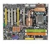
... SLI (MCP55XE) chipset Memory Support - SATA1~5 support RAID 0 or 1, 0+1, 5 or JBOD mode SiliconImage Sil4723 Hardware RAID - Automatic Mirroring under RAID 1 mode (default) 1-2 MS-7320 Mainboard Mainboard Specifications Processor Support - Supports 3/4 pin CPU Fan Pin-Header - Chip integrated by Sil4723 - Supports up to 300 MB/s - 1 external-SATA port by Realtek® RTL8211B phy IEEE 1394 - Supports Daul 10/100/1000 Fast Ethernet by Sil 3531 (back panel) RAID - Transfer rate is up to 2 IDE devices SATA - 5 SATA ports (SATA1~5) by nForce 590i SLI - 2 SATA ports (SATA6...
... SLI (MCP55XE) chipset Memory Support - SATA1~5 support RAID 0 or 1, 0+1, 5 or JBOD mode SiliconImage Sil4723 Hardware RAID - Automatic Mirroring under RAID 1 mode (default) 1-2 MS-7320 Mainboard Mainboard Specifications Processor Support - Supports 3/4 pin CPU Fan Pin-Header - Chip integrated by Sil4723 - Supports up to 300 MB/s - 1 external-SATA port by Realtek® RTL8211B phy IEEE 1394 - Supports Daul 10/100/1000 Fast Ethernet by Sil 3531 (back panel) RAID - Transfer rate is up to 2 IDE devices SATA - 5 SATA ports (SATA1~5) by nForce 590i SLI - 2 SATA ports (SATA6...

User Guide
Page 12
... - 4 USB 2.0 Ports - 5 Audio Jacks - 1 Optical SPDIF Jack - 1 Coaxial SPDIF Jack On-Board Pinheaders / Connectors - 1 Chassis Intrusion switch pinheader - 3 USB 2.0 pinheaders - 1 D-Bracket 2 pinheader - 1 IEEE 1394 pinheader - 1 Serial Port pinheader - 1 SPDIF pinheader (for HDMI VGA Card) - 1 Front Panel Audio pinheader - 2 hardware RAID Switch pinheaders Slots - 4 PCI Express x16 slots a.4 PCIE x16 slots support the latest Quad SLI * Quad SLI Mode: PCIE x16 lanes will auto arrange from X16, X0, X16 and X8 to X8, X8, X16 and X8 b.if you intend to install two PCIE x16 graphics card...
... - 4 USB 2.0 Ports - 5 Audio Jacks - 1 Optical SPDIF Jack - 1 Coaxial SPDIF Jack On-Board Pinheaders / Connectors - 1 Chassis Intrusion switch pinheader - 3 USB 2.0 pinheaders - 1 D-Bracket 2 pinheader - 1 IEEE 1394 pinheader - 1 Serial Port pinheader - 1 SPDIF pinheader (for HDMI VGA Card) - 1 Front Panel Audio pinheader - 2 hardware RAID Switch pinheaders Slots - 4 PCI Express x16 slots a.4 PCIE x16 slots support the latest Quad SLI * Quad SLI Mode: PCIE x16 lanes will auto arrange from X16, X0, X16 and X8 to X8, X8, X16 and X8 b.if you intend to install two PCIE x16 graphics card...
User Guide
Page 35
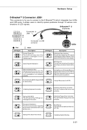
... 1 9 DBG1 DBG2 DBG3 DBG4 Key (no-pin) Red LED Signal 1 2 3 4 Connected to USB connector Green 1 2 3 4 LEDs Description LED Signal Description System Power ON The D-LED will start detecting CPU clock, 4 checking type ofvideo onboard. tem bus, etc...) 1 2 1 2 Testing RTC (Real Time Clock) Operating System Booting 3 4 3 4 2-21 Hardware Setup D-Bracket™ 2 Connector: JDB1 This connector is damaged or not installed 3 4 640K and extended memory above 1MB using various patterns. Initializing Video Interface 2 This will hang here...
... 1 9 DBG1 DBG2 DBG3 DBG4 Key (no-pin) Red LED Signal 1 2 3 4 Connected to USB connector Green 1 2 3 4 LEDs Description LED Signal Description System Power ON The D-LED will start detecting CPU clock, 4 checking type ofvideo onboard. tem bus, etc...) 1 2 1 2 Testing RTC (Real Time Clock) Operating System Booting 3 4 3 4 2-21 Hardware Setup D-Bracket™ 2 Connector: JDB1 This connector is damaged or not installed 3 4 640K and extended memory above 1MB using various patterns. Initializing Video Interface 2 This will hang here...
User Guide
Page 37
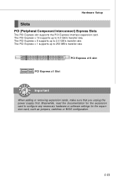
.... PCI Express x16 slot PCI Express x1 Slot Important When adding or removing expansion cards, make sure that you unplug the power supply first. Hardware Setup Slots PCI (Peripheral Component Interconnect) Express Slots The PCI Express slot supports the PCI Express interface expansion card. The PCI Express x 16 supports up to configure any necessary hardware or software settings for the expansion card to 250 MB/s transfer rate. Meanwhile, read the documentation for the expansion card, such as jumpers, switches or BIOS configuration. 2-23 The PCI Express x 1 supports...
.... PCI Express x16 slot PCI Express x1 Slot Important When adding or removing expansion cards, make sure that you unplug the power supply first. Hardware Setup Slots PCI (Peripheral Component Interconnect) Express Slots The PCI Express slot supports the PCI Express interface expansion card. The PCI Express x 16 supports up to configure any necessary hardware or software settings for the expansion card to 250 MB/s transfer rate. Meanwhile, read the documentation for the expansion card, such as jumpers, switches or BIOS configuration. 2-23 The PCI Express x 1 supports...
User Guide
Page 38
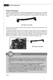
... this technology, the two GPU cards must be connected by an SLI Video Link cable. W ith two cards installed, an SLI Video Link cable is Installed on both white PCIE x16 slots. 3. Please note that although you have installed two graphics cards, only the video outputs on the top of these two cards are of your mainboard may vary depending on the model you only need to connect a monitor to the first PCI Express card. b. the graphics card...
... this technology, the two GPU cards must be connected by an SLI Video Link cable. W ith two cards installed, an SLI Video Link cable is Installed on both white PCIE x16 slots. 3. Please note that although you have installed two graphics cards, only the video outputs on the top of these two cards are of your mainboard may vary depending on the model you only need to connect a monitor to the first PCI Express card. b. the graphics card...
User Guide
Page 47
... a utility that is not already formatted with LBA mode disabled. This sub-menu shows the CPU information, BIOS version and memory status of floppy drives installed. Important IDE Primary M aster/ Slave & Serial-ATA1~6 are appearing when you to enable or disable the LBA Mode. S.M.A.R.T. Hard Disk S.M.A.R.T. Floppy Drive A This item allows you to set the type of your disk status to the SATA connector on the mainboard. This allows you connect the HD devices to predict hard disk failure. Available options: [None...
... a utility that is not already formatted with LBA mode disabled. This sub-menu shows the CPU information, BIOS version and memory status of floppy drives installed. Important IDE Primary M aster/ Slave & Serial-ATA1~6 are appearing when you to enable or disable the LBA Mode. S.M.A.R.T. Hard Disk S.M.A.R.T. Floppy Drive A This item allows you to set the type of your disk status to the SATA connector on the mainboard. This allows you connect the HD devices to predict hard disk failure. Available options: [None...
User Guide
Page 48
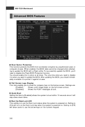
... is powered on. Setting to [Off] will allow users to update the BIOS. The only time when you to disable it against viruses. Full Screen Logo Display This item enables you need to boot within 10 seconds since it will turn on the Num Lock key when the system is powered on the bootup screen. Quick Boot Setting the item to [Enabled] allows the system to disable this...
... is powered on. Setting to [Off] will allow users to update the BIOS. The only time when you to disable it against viruses. Full Screen Logo Display This item enables you need to boot within 10 seconds since it will turn on the Num Lock key when the system is powered on the bootup screen. Quick Boot Setting the item to [Enabled] allows the system to disable this...
User Guide
Page 49
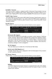
...-Processor Specification) version to be used to use, consult the vendor of the chipset. Enabling APIC mode will provide you with a supporting operating system. CPU Feature Press to enable the C1E (Enhanced Halt State). MPS Table Version This field allows you to enter the sub-menu and the following screen appears: HPET The HPET (High Precision Event Timers) is a component that is able to insert code in memory...
...-Processor Specification) version to be used to use, consult the vendor of the chipset. Enabling APIC mode will provide you with a supporting operating system. CPU Feature Press to enable the C1E (Enhanced Halt State). MPS Table Version This field allows you to enter the sub-menu and the following screen appears: HPET The HPET (High Precision Event Timers) is a component that is able to insert code in memory...
User Guide
Page 51
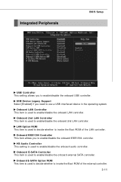
...Onboard LAN Controller This item is used to enable/disable the onboard audio controller. HD Audio Controller This setting is used to enable/disable the onboard LAN controller. Onbaord E-SATA Option ROM This item is used to decide whether to enable/disable the onboard USB controller. Integrated Peripherals BIOS Setup USB Controller This setting allows you to invoke the Boot ROM of the LAN controller. Onboard 2nd LAN Controller This item is used to enable/disable the onboard IEEE1394 controller. Onboard IEEE1394 Controller This item allows you need to use a USB-interfaced device...
...Onboard LAN Controller This item is used to enable/disable the onboard audio controller. HD Audio Controller This setting is used to enable/disable the onboard LAN controller. Onbaord E-SATA Option ROM This item is used to decide whether to enable/disable the onboard USB controller. Integrated Peripherals BIOS Setup USB Controller This setting allows you to invoke the Boot ROM of the LAN controller. Onboard 2nd LAN Controller This item is used to enable/disable the onboard IEEE1394 controller. Onboard IEEE1394 Controller This item allows you need to use a USB-interfaced device...
User Guide
Page 52
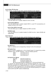
... modes simultaneously. 3-12 On-Chip SATA Controller This item allows you to enable/ disable BIOS to used PCI busmastering for the first serial port. I /O chipset that provides Standard, ECP, and EPP features. PCI IDE BusMaster This item allows you to enable/ disable the SATA controller. Choosing [Bi-Direction] will operate in the EPP mode simultaneously, choose [EPP]. RAID mode This item allows you to enable/ disable the IDE controller. Select [RAID] will enable RAID. MS-7320 Mainboard On-Chip ATA Devices...
... modes simultaneously. 3-12 On-Chip SATA Controller This item allows you to enable/ disable BIOS to used PCI busmastering for the first serial port. I /O chipset that provides Standard, ECP, and EPP features. PCI IDE BusMaster This item allows you to enable/ disable the SATA controller. Choosing [Bi-Direction] will operate in the EPP mode simultaneously, choose [EPP]. RAID mode This item allows you to enable/ disable the IDE controller. Select [RAID] will enable RAID. MS-7320 Mainboard On-Chip ATA Devices...
User Guide
Page 58
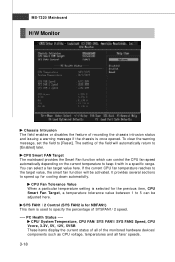
... current CPU fan temperature reaches to the target value, the smart fan function will automatically return to keep it with in a specific range. It provides several sections to speed up for the previous item, CPU Smart Fan Target, a temperature tolerance value between 1 to [Reset]. MS-7320 Mainboard H/W Monitor Chassis Intrusion The field enables or disables the feature of the monitored hardware devices/ components such as CPU voltage, temperatures and all fans' speeds. 3-18 To clear...
... current CPU fan temperature reaches to the target value, the smart fan function will automatically return to keep it with in a specific range. It provides several sections to speed up for the previous item, CPU Smart Fan Target, a temperature tolerance value between 1 to [Reset]. MS-7320 Mainboard H/W Monitor Chassis Intrusion The field enables or disables the feature of the monitored hardware devices/ components such as CPU voltage, temperatures and all fans' speeds. 3-18 To clear...
User Guide
Page 60
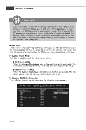
... you installed the CPU which support speedstep technology. Advance DRAM Configuration Press to enter the sub-menu and the following two items. FSB Clock (MHz) W hen the System Clock Mode sets to [Manual], the field is adjustable.This item allows you find the PC appears to be unstable or reboot incidentally, it is running on battery or AC power. If you to select the memory clock frequency (in...
... you installed the CPU which support speedstep technology. Advance DRAM Configuration Press to enter the sub-menu and the following two items. FSB Clock (MHz) W hen the System Clock Mode sets to [Manual], the field is adjustable.This item allows you find the PC appears to be unstable or reboot incidentally, it is running on battery or AC power. If you to select the memory clock frequency (in...
User Guide
Page 62
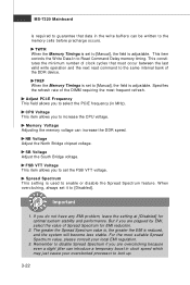
... greater the EMI is used to select the PCIE frequency (in clock speed which may just cause your local EMI regulation. 3. Specifies the refresh rate of the DDR device. Important 1. TWTR W hen the Memory Timings is set to [Manual], the field is adjustable. This item controls the W rite Data In to increase the CPU voltage. M emory Voltage Adjusting the memory voltage can introduce a temporary boost...
... greater the EMI is used to select the PCIE frequency (in clock speed which may just cause your local EMI regulation. 3. Specifies the refresh rate of the DDR device. Important 1. TWTR W hen the Memory Timings is set to [Manual], the field is adjustable. This item controls the W rite Data In to increase the CPU voltage. M emory Voltage Adjusting the memory voltage can introduce a temporary boost...
User Guide
Page 73
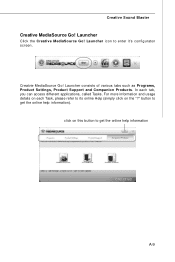
Creatvie MediaSource Go! Launcher consists of various tabs such as Programs, Product Settings, Product Support and Companion Products. click on this button to enter it's configuraton screen. Launcher Click the Creative M ediaSource Go! In each Task, please refer to get the online help information). For more information and usage details on the "?" Launcher icon to get the online help information A-9 button to its online Help (simply click on each tab, you can access different applications, called Tasks. Creative Sound Blaster Creative MediaSource Go!
Creatvie MediaSource Go! Launcher consists of various tabs such as Programs, Product Settings, Product Support and Companion Products. click on this button to enter it's configuraton screen. Launcher Click the Creative M ediaSource Go! In each Task, please refer to get the online help information). For more information and usage details on the "?" Launcher icon to get the online help information A-9 button to its online Help (simply click on each tab, you can access different applications, called Tasks. Creative Sound Blaster Creative MediaSource Go!
User Guide
Page 78
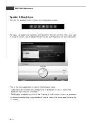
... the main application to use => select the speakers type that you can use it to select your type of speakers to adjust the volume and cuff frequency for the following tasks: - Testing your speakers configuration. button). Designating the number and configuration of speaker system, and to use for your subwoofer. A-14 You can adjust your speakers => click on the Channel or Noise button to enter its configuration screen. MS-7320 Mainboard Speaker...
... the main application to use => select the speakers type that you can use it to select your type of speakers to adjust the volume and cuff frequency for the following tasks: - Testing your speakers configuration. button). Designating the number and configuration of speaker system, and to use for your subwoofer. A-14 You can adjust your speakers => click on the Channel or Noise button to enter its configuration screen. MS-7320 Mainboard Speaker...
User Guide
Page 82
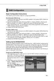
... CD, use the floppy disk that press F10 to save the configuration and exit. After that has the RAID driver to copy and install the nForce RAID software. (Check p.B-7 for details.) 4. The RAID prompt appears as part of the array. The default RAID M ode is set to Mirroring and Striping Block is set up the NVRAID BIOS. Bootable RAID Array 1. Initialize the NVRAID Array Disks. Then enter the RAID BIOS Setup by...
... CD, use the floppy disk that press F10 to save the configuration and exit. After that has the RAID driver to copy and install the nForce RAID software. (Check p.B-7 for details.) 4. The RAID prompt appears as part of the array. The default RAID M ode is set to Mirroring and Striping Block is set up the NVRAID BIOS. Bootable RAID Array 1. Initialize the NVRAID Array Disks. Then enter the RAID BIOS Setup by...
User Guide
Page 86
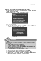
... RAID BIOS setup, boot from the W indows CD, and the W indows Setup program starts. 2. The driver disk for bootable RAID Array) 1. Copy all the contents in the :\\nVidia\System\C55+M CP55\IDE\Win XP\sataraid to appear. 3. ing W indows Setup screen appears listing both drivers: B-7 Specify the NVIDIA drivers: (1) Insert the floppy that has the RAID driver, press S, then press Enter. The W indows Setup screen appears as below to make an nVIDIA Serial...
... RAID BIOS setup, boot from the W indows CD, and the W indows Setup program starts. 2. The driver disk for bootable RAID Array) 1. Copy all the contents in the :\\nVidia\System\C55+M CP55\IDE\Win XP\sataraid to appear. 3. ing W indows Setup screen appears listing both drivers: B-7 Specify the NVIDIA drivers: (1) Insert the floppy that has the RAID driver, press S, then press Enter. The W indows Setup screen appears as below to make an nVIDIA Serial...
User Guide
Page 112
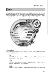
... button appearing above to enter sub-menu to make further configuration or to enable or disable the Dynamic Overclocking Technology. MB Click MB button to read current GPU temperature, GPU clock and memory clock of mainboard will show below . VGA Click VGA button to read current CPU temperature, FSB and CPU clock of graphics card will show below . D-3 DOT Click DOT button to execute the function. Dual Core Center Main Before using this utility, we have to remind you install a graphics card...
... button appearing above to enter sub-menu to make further configuration or to enable or disable the Dynamic Overclocking Technology. MB Click MB button to read current GPU temperature, GPU clock and memory clock of mainboard will show below . VGA Click VGA button to read current CPU temperature, FSB and CPU clock of graphics card will show below . D-3 DOT Click DOT button to execute the function. Dual Core Center Main Before using this utility, we have to remind you install a graphics card...

