User Guide
Page 2
Alternatively, please try the following help resources for FAQ, technical guide, BIOS updates, driver updates, and other countries. We take every care in the preparation of this document is the intellectual property of M ICRO-STAR INTERNATIONAL...of their respective owners. AMI® is a registered trademark of American Megatrends Inc. Netware® is given as to make changes without notice. Visit the MSI website for further guidance. AMD, Athlon™, Athlon™ XP, Thoroughbred™, and Duron™ are registered trademarks of Intel Corporation. Intel® ...
Alternatively, please try the following help resources for FAQ, technical guide, BIOS updates, driver updates, and other countries. We take every care in the preparation of this document is the intellectual property of M ICRO-STAR INTERNATIONAL...of their respective owners. AMI® is a registered trademark of American Megatrends Inc. Netware® is given as to make changes without notice. Visit the MSI website for further guidance. AMD, Athlon™, Athlon™ XP, Thoroughbred™, and Duron™ are registered trademarks of Intel Corporation. Intel® ...
User Guide
Page 8
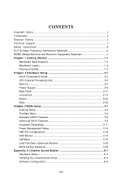
... 2-1 Quick Components Guide 2-2 CPU (Central Processing Unit 2-3 Memory ...2-7 Power Supply ...2-9 Back Panel ...2-11 Connectors ...2-13 Button ...2-22 Slots ...2-23 Chapter 3 BIOS Setup 3-1 Entering Setup ...3-2 The Main Menu ...3-4 Standard CMOS Features 3-6 Advanced BIOS Features 3-8 Integrated Peripherals 3-11 Power Management Setup 3-13 PNP/PCI Configurations 3-16 H/W Monitor ...3-18 Cell Menu ...3-19 Load Fail-Safe...
... 2-1 Quick Components Guide 2-2 CPU (Central Processing Unit 2-3 Memory ...2-7 Power Supply ...2-9 Back Panel ...2-11 Connectors ...2-13 Button ...2-22 Slots ...2-23 Chapter 3 BIOS Setup 3-1 Entering Setup ...3-2 The Main Menu ...3-4 Standard CMOS Features 3-6 Advanced BIOS Features 3-8 Integrated Peripherals 3-11 Power Management Setup 3-13 PNP/PCI Configurations 3-16 H/W Monitor ...3-18 Cell Menu ...3-19 Load Fail-Safe...
User Guide
Page 20
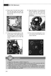
.... Press the four hooks down the load lever lightly onto the load plate, and then secure the lever with the plastic cap covered (shown in BIOS (Chapter 3). 2. The appearance of your CPU socket pin with the hook under retention tab. 10. Press down to avoid damaging. 3.
.... Press the four hooks down the load lever lightly onto the load plate, and then secure the lever with the plastic cap covered (shown in BIOS (Chapter 3). 2. The appearance of your CPU socket pin with the hook under retention tab. 10. Press down to avoid damaging. 3.

User Guide
Page 30
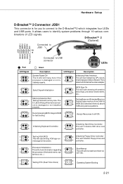
.... CPUFAN1 supports fan control. The system will automatically control the CPU fan speed according to the +12V; To clear the warning, you must enter the BIOS utility and clear the record. 2 GND 1 CINTRU JCI1 2-16 You can install Dual Core Center utility that the red wire is Ground and should be...
.... CPUFAN1 supports fan control. The system will automatically control the CPU fan speed according to the +12V; To clear the warning, you must enter the BIOS utility and clear the record. 2 GND 1 CINTRU JCI1 2-16 You can install Dual Core Center utility that the red wire is Ground and should be...
User Guide
Page 35
... Initializing Keyboard Controller. 1 2 Initializing Hard Drive Controller This will initialize IDE drive and 3 4 3 4 controller. 1 2 Testing VGA BIOS 1 2 Initializing Floppy Drive Controller This will start detecting CPU clock, 4 checking type ofvideo onboard. Initializing Video Interface 2 This will start ... etc...) 1 2 1 2 Testing RTC (Real Time Clock) Operating System Booting 3 4 3 4 2-21 properly. 1 2 Decompressing BIOS image to RAM 1 2 Assign Resources to the screen. 3 4 controller. 1 Processor Initialization 2 This will show information regarding 1 2 ...
... Initializing Keyboard Controller. 1 2 Initializing Hard Drive Controller This will initialize IDE drive and 3 4 3 4 controller. 1 2 Testing VGA BIOS 1 2 Initializing Floppy Drive Controller This will start detecting CPU clock, 4 checking type ofvideo onboard. Initializing Video Interface 2 This will start ... etc...) 1 2 1 2 Testing RTC (Real Time Clock) Operating System Booting 3 4 3 4 2-21 properly. 1 2 Decompressing BIOS image to RAM 1 2 Assign Resources to the screen. 3 4 controller. 1 Processor Initialization 2 This will show information regarding 1 2 ...
User Guide
Page 37
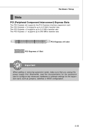
... 4.0 GB/s transfer rate. The PCI Express x 8 supports up to configure any necessary hardware or software settings for the expansion card, such as jumpers, switches or BIOS configuration. 2-23 Hardware Setup Slots PCI (Peripheral Component Interconnect) Express Slots The PCI Express slot supports the PCI Express interface expansion card. PCI Express x16...
... 4.0 GB/s transfer rate. The PCI Express x 8 supports up to configure any necessary hardware or software settings for the expansion card, such as jumpers, switches or BIOS configuration. 2-23 Hardware Setup Slots PCI (Peripheral Component Interconnect) Express Slots The PCI Express slot supports the PCI Express interface expansion card. PCI Express x16...
User Guide
Page 41
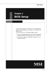
You may need to run the Setup program when: ² An error message appears on the BIOS Setup program and allows you to run SETUP. ² You want to configure the system for customized features. 3-1 Chapter 3 BIOS Setup BIOS Setup This chapter provides information on the screen during the system booting up, and requests you to change the default settings for optimum use.
You may need to run the Setup program when: ² An error message appears on the BIOS Setup program and allows you to run SETUP. ² You want to configure the system for customized features. 3-1 Chapter 3 BIOS Setup BIOS Setup This chapter provides information on the screen during the system booting up, and requests you to change the default settings for optimum use.
User Guide
Page 42
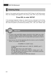
...turning it OFF and On or pressing the RESET button. Upon boot-up, the 1st line appearing after the memory count is usually in this BIOS was released. 3-2 MS-7320 Mainboard Entering Setup Power on the screen, press key to enter Setup, restart the system by simultaneously pressing , ..., and keys. It is the BIOS version. W hen the message below appears on the computer and the system will start POST (Power On Self Test) process. The items under continuous...
...turning it OFF and On or pressing the RESET button. Upon boot-up, the 1st line appearing after the memory count is usually in this BIOS was released. 3-2 MS-7320 Mainboard Entering Setup Power on the screen, press key to enter Setup, restart the system by simultaneously pressing , ..., and keys. It is the BIOS version. W hen the message below appears on the computer and the system will start POST (Power On Self Test) process. The items under continuous...
User Guide
Page 43
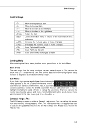
... on-line description of the highlighted setup function is the Main Menu. You can use and the possible selections for a field parameter. General Help The BIOS setup program provides a General Help screen. The Help screen lists the appropriate keys to select the item. You can use the arrow keys ( ↑&#... ) to use arrow keys ( ↑↓ ) to highlight the field and press to the main menu from field to the main menu, just press the . BIOS Setup Control Keys Enter> Move to the previous item Move to the next item Move to the item in the right hand Select the item...
... on-line description of the highlighted setup function is the Main Menu. You can use and the possible selections for a field parameter. General Help The BIOS setup program provides a General Help screen. The Help screen lists the appropriate keys to select the item. You can use the arrow keys ( ↑&#... ) to use arrow keys ( ↑↓ ) to highlight the field and press to the main menu from field to the main menu, just press the . BIOS Setup Control Keys Enter> Move to the previous item Move to the next item Move to the item in the right hand Select the item...
User Guide
Page 44
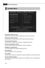
... management. PNP/PCI Configurations This entry appears if your PC health status. Cell Menu Use this menu to load the default values set by the BIOS vendor for frequency/voltage control and overclocking. Load Fail-Safe Defaults Use this menu to specify your settings for basic system configurations, such as time...
... management. PNP/PCI Configurations This entry appears if your PC health status. Cell Menu Use this menu to load the default values set by the BIOS vendor for frequency/voltage control and overclocking. Load Fail-Safe Defaults Use this menu to specify your settings for basic system configurations, such as time...

User Guide
Page 45
Exit Without Saving Abandon all changes and exit setup. 3-5 BIOS Setup Load Optimized Defaults Use this menu to set by the mainboard manufacturer specifically for BIOS. Save & Exit Setup Save changes to load the default values set the password for optimal performance of the mainboard. BIOS Setting Password Use this menu to CMOS and exit setup.
Exit Without Saving Abandon all changes and exit setup. 3-5 BIOS Setup Load Optimized Defaults Use this menu to set by the mainboard manufacturer specifically for BIOS. Save & Exit Setup Save changes to load the default values set the password for optimal performance of the mainboard. BIOS Setting Password Use this menu to CMOS and exit setup.
User Guide
Page 46
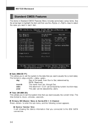
Read-only. date The date from 1 to 31 can be keyed by BIOS. The format is . through Dec. day Day of the week, from Jan. Device/ Vender/ Size It will showing the device information that you connected to ...
Read-only. date The date from 1 to 31 can be keyed by BIOS. The format is . through Dec. day Day of the week, from Jan. Device/ Vender/ Size It will showing the device information that you connected to ...
User Guide
Page 47
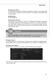
... are appearing when you connect the HD devices to predict hard disk failure. System Information Press to enable or disable the LBA Mode. BIOS Setup LBA/Large M ode This allows you to enter the sub-menu, and the following screen appears. This allows you an opportunity ... Available options: [None], [360K, 5.25 in.], [1.2M, 5.25 in.], [720K, 3.5 in.], [1.44M, 3.5 in.], [2.88M, 3.5 in.]. This sub-menu shows the CPU information, BIOS version and memory status of floppy drives installed. This gives you to a safe place before the hard disk becomes offline. Setting to set the type...
... are appearing when you connect the HD devices to predict hard disk failure. System Information Press to enable or disable the LBA Mode. BIOS Setup LBA/Large M ode This allows you to enter the sub-menu, and the following screen appears. This allows you an opportunity ... Available options: [None], [360K, 5.25 in.], [1.2M, 5.25 in.], [720K, 3.5 in.], [1.44M, 3.5 in.], [2.88M, 3.5 in.]. This sub-menu shows the CPU information, BIOS version and memory status of floppy drives installed. This gives you to a safe place before the hard disk becomes offline. Setting to set the type...
User Guide
Page 48
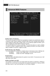
...image (logo) on the full screen at boot. [Disabled] Shows the POST messages at all times. The only time when you should enable this Flash BIOS Protection function. Quick Boot Setting the item to [Enabled] allows the system to boot within 10 seconds since it is powered on the numeric keypad.... 3-8 After updating the BIOS, you need to update the BIOS. Setting to use the arrow keys on . Setting to [Off] will allow users to [On] will skip some check items. Boot Up...
...image (logo) on the full screen at boot. [Disabled] Shows the POST messages at all times. The only time when you should enable this Flash BIOS Protection function. Quick Boot Setting the item to [Enabled] allows the system to boot within 10 seconds since it is powered on the numeric keypad.... 3-8 After updating the BIOS, you need to update the BIOS. Setting to use the arrow keys on . Setting to [Off] will allow users to [On] will skip some check items. Boot Up...
User Guide
Page 49
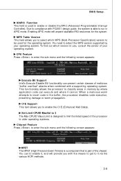
... Max CPUID Value Limit is designed to limit the listed speed of the chipset. You can execute and where it via the various ACPI methods. 3-9 BIOS Setup IOAPIC Function This field is used for the system. C1E Support This item allows you with a supporting operating system. This functionality allows the processor...
... Max CPUID Value Limit is designed to limit the listed speed of the chipset. You can execute and where it via the various ACPI methods. 3-9 BIOS Setup IOAPIC Function This field is used for the system. C1E Support This item allows you with a supporting operating system. This functionality allows the processor...
User Guide
Page 50
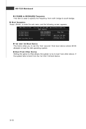
Boot From Other Device Setting the option to [Yes] allows the system to try to boot from the 1st/ 2nd/ 3rd boot device. 3-10 if the system fails to boot from other device. MS-7320 Mainboard C55(NB) to NVIDIA(SB) Frequency This item is used to specify the frequency from north bridge to load the disk operating system. Boot Sequence Press to enter the sub-menu and the following screen appears: 1st/ 2nd/ 3rd Boot Device The items allow you to set the first/ second/ third boot device where BIOS attempts to south beidge.
Boot From Other Device Setting the option to [Yes] allows the system to try to boot from the 1st/ 2nd/ 3rd boot device. 3-10 if the system fails to boot from other device. MS-7320 Mainboard C55(NB) to NVIDIA(SB) Frequency This item is used to specify the frequency from north bridge to load the disk operating system. Boot Sequence Press to enter the sub-menu and the following screen appears: 1st/ 2nd/ 3rd Boot Device The items allow you to set the first/ second/ third boot device where BIOS attempts to south beidge.
User Guide
Page 51
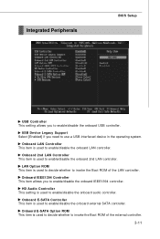
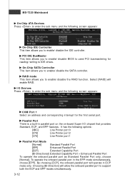
... is used to enable/disable the onboard LAN controller. HD Audio Controller This setting is used to enable/disable the onboard audio controller. Integrated Peripherals BIOS Setup USB Controller This setting allows you need to use a USB-interfaced device in the operating system. Onboard IEEE1394 Controller This item allows you to...
... is used to enable/disable the onboard LAN controller. HD Audio Controller This setting is used to enable/disable the onboard audio controller. Integrated Peripherals BIOS Setup USB Controller This setting allows you need to use a USB-interfaced device in the operating system. Onboard IEEE1394 Controller This item allows you to...
User Guide
Page 52
... Standard, ECP, and EPP features. By choosing [ECP], the onboard parallel port will enable RAID. PCI IDE BusMaster This item allows you to enable/ disable BIOS to used PCI busmastering for reading/ writing to enter the sub-menu and the following options: [3BC] Line Printer port 0 [278] Line Printer port 2 [378...
... Standard, ECP, and EPP features. By choosing [ECP], the onboard parallel port will enable RAID. PCI IDE BusMaster This item allows you to enable/ disable BIOS to used PCI busmastering for reading/ writing to enter the sub-menu and the following options: [3BC] Line Printer port 0 [278] Line Printer port 2 [378...
User Guide
Page 53
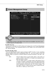
... setting of system configuration and open applications/files is to restore the system when a "wake up" event occurs. 3-13 If your BIOS supports S3 sleep mode. Set- Power Management Setup BIOS Setup Important S3-related functions described in this section are : [S1] The S1 sleep mode is lost (CPU or chipset) and...
... setting of system configuration and open applications/files is to restore the system when a "wake up" event occurs. 3-13 If your BIOS supports S3 sleep mode. Set- Power Management Setup BIOS Setup Important S3-related functions described in this section are : [S1] The S1 sleep mode is lost (CPU or chipset) and...

User Guide
Page 55
BIOS Setup Resume by RTC Alarm The field is used to be awakened from the power saving modes through any event on a scheduled time/date. 3-15 Resume by Onbaord LAN W hen set to [Enabled], the feature allows your system to enable or disable the feature of booting up the system on LAN device.
BIOS Setup Resume by RTC Alarm The field is used to be awakened from the power saving modes through any event on a scheduled time/date. 3-15 Resume by Onbaord LAN W hen set to [Enabled], the feature allows your system to enable or disable the feature of booting up the system on LAN device.


