User Guide
Page 3
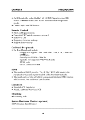
Remote Control l Meet ACPI specifications. Dimension l Standard ATX form factor l 30cm(L) x 18.6cm(W) x 4 layer PCB Mounting l 6 mounting holes System Hardware Monitor (optional) l CPU Rotation Speed Control 1-3 l Connect up . BIOS l The mainboard BIOS provides "Plug & Play" BIOS which records your mainboard specifications. l Soft Power-Off. l Power ON/OFF switch connector on the Aladdin® M1543 PCI...
Remote Control l Meet ACPI specifications. Dimension l Standard ATX form factor l 30cm(L) x 18.6cm(W) x 4 layer PCB Mounting l 6 mounting holes System Hardware Monitor (optional) l CPU Rotation Speed Control 1-3 l Connect up . BIOS l The mainboard BIOS provides "Plug & Play" BIOS which records your mainboard specifications. l Soft Power-Off. l Power ON/OFF switch connector on the Aladdin® M1543 PCI...

User Guide
Page 24
You can connect up to four hard disk drives, CD-ROM, 120MB Floppy (reserved for future BIOS) and other devices to IDE1. CHAPTER 2 HARDWARE INSTALLATION 2.9 Hard Disk Connectors: IDE1 & IDE2 The mainboard has a 32-bit Enhanced PCI IDE Controller that provides two ...
You can connect up to four hard disk drives, CD-ROM, 120MB Floppy (reserved for future BIOS) and other devices to IDE1. CHAPTER 2 HARDWARE INSTALLATION 2.9 Hard Disk Connectors: IDE1 & IDE2 The mainboard has a 32-bit Enhanced PCI IDE Controller that provides two ...

User Guide
Page 31
The following pages will describe how to modify this information. CHAPTER 3 AMI® BIOS USER’S GUIDE Chapter 3 AMI® BIOS USER GUIDE The system configuration information and chipset register information is off. This information is retained by a battery when the power is stored in the CMOS RAM. Enter the BIOS setup (if needed) to enter BIOS setup, and all about options. 3-1
The following pages will describe how to modify this information. CHAPTER 3 AMI® BIOS USER’S GUIDE Chapter 3 AMI® BIOS USER GUIDE The system configuration information and chipset register information is off. This information is retained by a battery when the power is stored in the CMOS RAM. Enter the BIOS setup (if needed) to enter BIOS setup, and all about options. 3-1
User Guide
Page 32
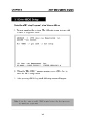
...want to modify CMOS original setting, then don't press any key during the system boot. 3-2 After pressing key, the BIOS setup screen will appear. CHAPTER 3 AMI® BIOS USER’S GUIDE 3.1 Enter BIOS Setup Enter the AMI® setup Program's Main Menu as follows: 1. AMIBIOS (C) 1998 American Megatrends Inc. Note: ...to run setup (C) American Megatrends Inc. 61-XXXX-001169-00111111-071592-i82440FX-H 2. When the "Hit " message appears, press key to enter the BIOS setup screen. 3. The following screen appears with a series of diagnostic check. Turn on or reboot the system.
...want to modify CMOS original setting, then don't press any key during the system boot. 3-2 After pressing key, the BIOS setup screen will appear. CHAPTER 3 AMI® BIOS USER’S GUIDE 3.1 Enter BIOS Setup Enter the AMI® setup Program's Main Menu as follows: 1. AMIBIOS (C) 1998 American Megatrends Inc. Note: ...to run setup (C) American Megatrends Inc. 61-XXXX-001169-00111111-071592-i82440FX-H 2. When the "Hit " message appears, press key to enter the BIOS setup screen. 3. The following screen appears with a series of diagnostic check. Turn on or reboot the system.
User Guide
Page 33
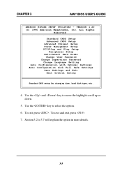
... 3.2 to select the option. 6. Use the and key to move the highlight scroll up or down. 5. VERSION 1.20 (C) 1996 American Megatrends, Inc. CHAPTER 3 AMI® BIOS USER’S GUIDE AMIBIOS HIFLEX SETUP UTILITIES - To exit, press .
... 3.2 to select the option. 6. Use the and key to move the highlight scroll up or down. 5. VERSION 1.20 (C) 1996 American Megatrends, Inc. CHAPTER 3 AMI® BIOS USER’S GUIDE AMIBIOS HIFLEX SETUP UTILITIES - To exit, press .

User Guide
Page 34
... the main menu screen . After you have finished with the Standard CMOS Setup, press to go back to modify the highlighted item. 3. CHAPTER 3 AMI® BIOS USER’S GUIDE 3.2 Standard CMOS Setup 1.
... the main menu screen . After you have finished with the Standard CMOS Setup, press to go back to modify the highlighted item. 3. CHAPTER 3 AMI® BIOS USER’S GUIDE 3.2 Standard CMOS Setup 1.
User Guide
Page 35
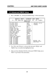
CHAPTER 3 AMI® BIOS USER’S GUIDE 3.3 Advanced CMOS Setup 1. Use and to choose the item and and keys to the main menu. 3-5 After you have finished with the ... Drive Swap Floppy Drive Seek Floppy Access Control HDD Access Control PS/2 Mouse Support Password Check Primary Display Boot to OS/2 External Cache System BIOS Cacheable Video BIOS Shadow C000, 16k Shadow C400, 16k Shadow C800, 16k Shadow CC00, 16k Shadow D000, 16k Shadow D400, 16k Shadow D800, 16k Shadow DC00, 16k...
CHAPTER 3 AMI® BIOS USER’S GUIDE 3.3 Advanced CMOS Setup 1. Use and to choose the item and and keys to the main menu. 3-5 After you have finished with the ... Drive Swap Floppy Drive Seek Floppy Access Control HDD Access Control PS/2 Mouse Support Password Check Primary Display Boot to OS/2 External Cache System BIOS Cacheable Video BIOS Shadow C000, 16k Shadow C400, 16k Shadow C800, 16k Shadow CC00, 16k Shadow D000, 16k Shadow D400, 16k Shadow D800, 16k Shadow DC00, 16k...
User Guide
Page 36
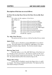
... default setting is Enabled. F(optical) The system will boot from the Network drive. Disable Disable this option to Enabled to permit AMI® BIOS to boot within 8 seconds. The end user can then use the arrow keys on screen follows: 1st Boot Device/2nd Boot Device/3rd Boot... Device/4th Boot Device This option sets the sequence of the item on both the numeric keypad and the keyboard. CHAPTER 3 AMI® BIOS USER’S GUIDE Description of boot drives. The settings are Enabled and Disabled. Try other Boot Devices This option sets the boot device, ...
... default setting is Enabled. F(optical) The system will boot from the Network drive. Disable Disable this option to Enabled to permit AMI® BIOS to boot within 8 seconds. The end user can then use the arrow keys on screen follows: 1st Boot Device/2nd Boot Device/3rd Boot... Device/4th Boot Device This option sets the sequence of the item on both the numeric keypad and the keyboard. CHAPTER 3 AMI® BIOS USER’S GUIDE Description of boot drives. The settings are Enabled and Disabled. Try other Boot Devices This option sets the boot device, ...
User Guide
Page 37
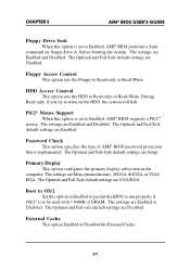
.... The settings are Enabled and Disabled. The settings are Enabled and Disabled. Floppy Access Control This option sets the Floppy to Enabled, AMI® BIOS supports a PS/2® mouse. The settings are VGA/EGA. The Optimal and Fail-Safe default settings are Mono(monochrome), 40CGA, 80CGA, or VGA... settings are Enabled or Disabled. PS/2® Mouse Support When this option is set to be used with > 64MB of AMI® BIOS password protection that is implemented. Password Check This option specifies the type of DRAM. The Optimal and Fail-Safe default settings are Enabled. ...
.... The settings are Enabled and Disabled. The settings are Enabled and Disabled. Floppy Access Control This option sets the Floppy to Enabled, AMI® BIOS supports a PS/2® mouse. The settings are VGA/EGA. The Optimal and Fail-Safe default settings are Mono(monochrome), 40CGA, 80CGA, or VGA... settings are Enabled or Disabled. PS/2® Mouse Support When this option is set to be used with > 64MB of AMI® BIOS password protection that is implemented. Password Check This option specifies the type of DRAM. The Optimal and Fail-Safe default settings are Enabled. ...

User Guide
Page 38
The Optimal default setting is not copied to RAM. Video BIOS Shadow Determines whether video BIOS will be copied to RAM for faster execution, it can also be written to and read from cache memory. the Video ROM is Enabled. The ... not copied to RAM. Video shadow will be written to or read from cache memory. Disabled - CHAPTER 3 AMI® BIOS USER’S GUIDE System BIOS Cacheable AMI® BIOS always copies the system BIOS from ROM to RAM for faster execution. Set this option to Enabled to permit the contents of the ROM area...
The Optimal default setting is not copied to RAM. Video BIOS Shadow Determines whether video BIOS will be copied to RAM for faster execution, it can also be written to and read from cache memory. the Video ROM is Enabled. The ... not copied to RAM. Video shadow will be written to or read from cache memory. Disabled - CHAPTER 3 AMI® BIOS USER’S GUIDE System BIOS Cacheable AMI® BIOS always copies the system BIOS from ROM to RAM for faster execution. Set this option to Enabled to permit the contents of the ROM area...
User Guide
Page 39
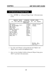
CHAPTER 3 AMI® BIOS USER’S GUIDE 3.4 Advanced Chipset Setup 1. ADVANCED CHIPSET SETUP (C) 1998 American Megatrends, Inc. After you have finished with the Advanced Chipset Setup, press to go ...
CHAPTER 3 AMI® BIOS USER’S GUIDE 3.4 Advanced Chipset Setup 1. ADVANCED CHIPSET SETUP (C) 1998 American Megatrends, Inc. After you have finished with the Advanced Chipset Setup, press to go ...
User Guide
Page 40
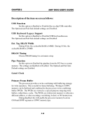
... Default settings are Enabled or Disabled. Gated Clock Primary Frame Buffer The processor provides a write-combining with buffering strategy for write operation. CHAPTER 3 AMI® BIOS USER’S GUIDE Description of the item on screen follows: USB Function Set this option to USWC memory can be buffered and combined in the...
... Default settings are Enabled or Disabled. Gated Clock Primary Frame Buffer The processor provides a write-combining with buffering strategy for write operation. CHAPTER 3 AMI® BIOS USER’S GUIDE Description of the item on screen follows: USB Function Set this option to USWC memory can be buffered and combined in the...

User Guide
Page 41
CHAPTER 3 AMI® BIOS USER’S GUIDE VGA Frame Buffer The processor provides a write-combining with buffering strategy for Cyrix processor which support linear burst mode. The WCBs are ...
CHAPTER 3 AMI® BIOS USER’S GUIDE VGA Frame Buffer The processor provides a write-combining with buffering strategy for Cyrix processor which support linear burst mode. The WCBs are ...

User Guide
Page 44
... Setup" of the main menu screen. Use and to choose the item and and keys to the main menu. 3-14 AMIBIOS SETUP - CHAPTER 3 AMI® BIOS USER’S GUIDE 3.5 Power Management Setup 1.
... Setup" of the main menu screen. Use and to choose the item and and keys to the main menu. 3-14 AMIBIOS SETUP - CHAPTER 3 AMI® BIOS USER’S GUIDE 3.5 Power Management Setup 1.

User Guide
Page 45
... settings are Disabled. Video Power Down Mode This option specifies the power conserving state that the green PC-compliant video monitor enters when AMI® BIOS places it in Full power on screen follows: Power Management/APM Set this length of time expires, the computer enters Standby power state. Hard Disk... This option specifies the power conserving state that the hard disk drive enters after the specified period of display inactivity has expired. CHAPTER 3 AMI® BIOS USER’S GUIDE Description of the item on state.
... settings are Disabled. Video Power Down Mode This option specifies the power conserving state that the green PC-compliant video monitor enters when AMI® BIOS places it in Full power on screen follows: Power Management/APM Set this length of time expires, the computer enters Standby power state. Hard Disk... This option specifies the power conserving state that the hard disk drive enters after the specified period of display inactivity has expired. CHAPTER 3 AMI® BIOS USER’S GUIDE Description of the item on state.

User Guide
Page 46
...;S GUIDE Suspend Time Out This option specifies the length of a period of time expires, the computer enters Suspend power state. AMI® BIOS reloads the Standby and Suspend timeout timers if activity occurs on power state if any incoming call from the modem. During Enabled, the system .../Monitor Pri-HDD/Monitor SecHDD When set to the operating system. When this length of system inactivity while in a power saving state, AMI® BIOS watches for activity on . 3-16 The settings are Disabled. During On/Off, the system will be turned off the system. This function will work...
...;S GUIDE Suspend Time Out This option specifies the length of a period of time expires, the computer enters Suspend power state. AMI® BIOS reloads the Standby and Suspend timeout timers if activity occurs on power state if any incoming call from the modem. During Enabled, the system .../Monitor Pri-HDD/Monitor SecHDD When set to the operating system. When this length of system inactivity while in a power saving state, AMI® BIOS watches for activity on . 3-16 The settings are Disabled. During On/Off, the system will be turned off the system. This function will work...

User Guide
Page 47
... it goes to boot up . RTC Alarm Second Choose which hour the system will boot up . During Disabled, you power on. 3-17 CHAPTER 3 AMI® BIOS USER’S GUIDE RTC Alarm Resume From Soft-Off This function is for setting the Date, Hour, Minute, and Second for your computer to the...
... it goes to boot up . RTC Alarm Second Choose which hour the system will boot up . During Disabled, you power on. 3-17 CHAPTER 3 AMI® BIOS USER’S GUIDE RTC Alarm Resume From Soft-Off This function is for setting the Date, Hour, Minute, and Second for your computer to the...

User Guide
Page 48
... highlighted item. 3. After you have finished with the PCI/Plug and Play Setup, press to go back to the main menu. 3-18 CHAPTER 3 AMI® BIOS USER’S GUIDE 3.6 PCI/Plug and Play Setup 1.
... highlighted item. 3. After you have finished with the PCI/Plug and Play Setup, press to go back to the main menu. 3-18 CHAPTER 3 AMI® BIOS USER’S GUIDE 3.6 PCI/Plug and Play Setup 1.

User Guide
Page 49
... on screen follows: Plug and Play Aware O/S Set this computer is PnP-aware. Data read and written by the CPU is disabled). CHAPTER 3 AMI® BIOS USER’S GUIDE Description of the item on every video device. Currently, only Windows 95® is aware of and follows the Plug and Play...
... on screen follows: Plug and Play Aware O/S Set this computer is PnP-aware. Data read and written by the CPU is disabled). CHAPTER 3 AMI® BIOS USER’S GUIDE Description of the item on every video device. Currently, only Windows 95® is aware of and follows the Plug and Play...
User Guide
Page 50
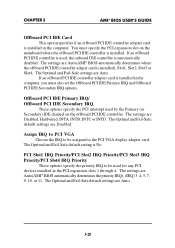
... be assigned to be used for any PCI devices installed in the computer. The settings are Auto(AMI® BIOS automatically determines the priority IRQ), (IRQ) 3, 4, 5, 7, 9, 10, or 11. CHAPTER 3 AMI® BIOS USER’S GUIDE Offboard PCI IDE Card This option specifies if an offboard PCI IDE controller adapter card is... Secondary) IDE channel on the mainboard where the offboard PCI IDE controller is installed. The Optimal and Fail-Safe default settings are Auto(AMI® BIOS automatically determines where the offboard PCI IDE controller adaper card is No.
... be assigned to be used for any PCI devices installed in the computer. The settings are Auto(AMI® BIOS automatically determines the priority IRQ), (IRQ) 3, 4, 5, 7, 9, 10, or 11. CHAPTER 3 AMI® BIOS USER’S GUIDE Offboard PCI IDE Card This option specifies if an offboard PCI IDE controller adapter card is... Secondary) IDE channel on the mainboard where the offboard PCI IDE controller is installed. The Optimal and Fail-Safe default settings are Auto(AMI® BIOS automatically determines where the offboard PCI IDE controller adaper card is No.


