User Guide
Page 1
...®6x86/6x86L/6x86MX, and AMD® K5/K6 processors. The ACPI provides more Energy Saving Features for the OSPM(OS Direct Power Management) function. The mainboard also supports the Hardware Monitor Controller as ACPI (Advanced Configuration and Power Interface). The mainboard also supports four 32-bit PCI (Peripheral Component Interconnect) Local Bus standard slots. The mainboard uses the highly integrated Aladdin® 5 chipset to support the PCI/ISA and Green standards, and...
...®6x86/6x86L/6x86MX, and AMD® K5/K6 processors. The ACPI provides more Energy Saving Features for the OSPM(OS Direct Power Management) function. The mainboard also supports the Hardware Monitor Controller as ACPI (Advanced Configuration and Power Interface). The mainboard also supports four 32-bit PCI (Peripheral Component Interconnect) Local Bus standard slots. The mainboard uses the highly integrated Aladdin® 5 chipset to support the PCI/ISA and Green standards, and...
User Guide
Page 2
... M1531/M1543 chipset. l Supports a maximum memory size of 768MB. On-Board IDE 1-2 Cache Memory l Supports 512K Pipelined Burst cache memory. AGP 66/133MHz 3.3v device support l Four 32-bit Master PCI Bus slots and three 16-bit ISA bus slots l Supports 3.3v/5v PCI bus Interface. CHAPTER 1 INTRODUCTION 1.1 Mainboard Features CPU l Socket 7 supports Intel® Pentium® processor/Pentium® processor with MMXTM technology. Slots l One AGP(Accelerated Graphics Port) slot. - Main Memory l Supports six memory banks using three 168-pin unbuffered DIMM. AGP specification compliant...
... M1531/M1543 chipset. l Supports a maximum memory size of 768MB. On-Board IDE 1-2 Cache Memory l Supports 512K Pipelined Burst cache memory. AGP 66/133MHz 3.3v device support l Four 32-bit Master PCI Bus slots and three 16-bit ISA bus slots l Supports 3.3v/5v PCI bus Interface. CHAPTER 1 INTRODUCTION 1.1 Mainboard Features CPU l Socket 7 supports Intel® Pentium® processor/Pentium® processor with MMXTM technology. Slots l One AGP(Accelerated Graphics Port) slot. - Main Memory l Supports six memory banks using three 168-pin unbuffered DIMM. AGP specification compliant...
User Guide
Page 3
.... - 2 serial ports (COMA + COMB) - 1 parallel port supports SPP/EPP/ECP mode - 2 USB ports - 1 IrDA connector for SIR. On-Board Peripherals l On-Board Peripherals include: - 1 floppy port supports 2 FDD with PIO, Bus Master and Ultra DMA/33 operation modes. l Soft Power-Off. l Support modem ring wake-up . l Support alarm wake-up . Dimension l Standard ATX form factor l 30cm(L) x 18.6cm(W) x 4 layer PCB Mounting l 6 mounting holes System Hardware Monitor (optional) l CPU Rotation Speed Control 1-3 Remote Control l Meet ACPI specifications. BIOS l The mainboard BIOS provides "Plug...
.... - 2 serial ports (COMA + COMB) - 1 parallel port supports SPP/EPP/ECP mode - 2 USB ports - 1 IrDA connector for SIR. On-Board Peripherals l On-Board Peripherals include: - 1 floppy port supports 2 FDD with PIO, Bus Master and Ultra DMA/33 operation modes. l Soft Power-Off. l Support modem ring wake-up . l Support alarm wake-up . Dimension l Standard ATX form factor l 30cm(L) x 18.6cm(W) x 4 layer PCB Mounting l 6 mounting holes System Hardware Monitor (optional) l CPU Rotation Speed Control 1-3 Remote Control l Meet ACPI specifications. BIOS l The mainboard BIOS provides "Plug...

User Guide
Page 24
Secondary IDE Connector Primary IDE Connector 1 1 IDE1(Primary IDE Connector) The first hard disk should always be connected to IDE1 and IDE2. IDE2(Secondary IDE Connector) IDE2 can connect up to four hard disk drives, CD-ROM, 120MB Floppy (reserved for future BIOS) and other devices to IDE1. You can connect a Master and a Slave drive. 2-19 CHAPTER 2 HARDWARE INSTALLATION 2.9 Hard Disk Connectors: IDE1 & IDE2 The mainboard has a 32-bit Enhanced PCI IDE Controller that provides two HDD connectors IDE1 (Primary) and IDE2 (Secondary...
Secondary IDE Connector Primary IDE Connector 1 1 IDE1(Primary IDE Connector) The first hard disk should always be connected to IDE1 and IDE2. IDE2(Secondary IDE Connector) IDE2 can connect up to four hard disk drives, CD-ROM, 120MB Floppy (reserved for future BIOS) and other devices to IDE1. You can connect a Master and a Slave drive. 2-19 CHAPTER 2 HARDWARE INSTALLATION 2.9 Hard Disk Connectors: IDE1 & IDE2 The mainboard has a 32-bit Enhanced PCI IDE Controller that provides two HDD connectors IDE1 (Primary) and IDE2 (Secondary...

User Guide
Page 29
You can plug a keyboard cable directly to this connector. It also provides a standard PS/2® mouse mini DIN connector for attaching USB devices like keyboard, mouse or etc. The connector location and pin definition as shown below: PS/2® Mouse (6-pin Female) PS/2® Keyboard (6-pin Female) 2.15 USB Connectors: USB The mainboard provide a USB(Universal Serial Bus) connector for attaching a PS/2® mouse. USB port 1 USB port 2 2-24 CHAPTER 2 HARDWARE INSTALLATION 2.14 Keyboard Connector: PSKBC Mouse Connector: PSMSC The mainboard provides...
You can plug a keyboard cable directly to this connector. It also provides a standard PS/2® mouse mini DIN connector for attaching USB devices like keyboard, mouse or etc. The connector location and pin definition as shown below: PS/2® Mouse (6-pin Female) PS/2® Keyboard (6-pin Female) 2.15 USB Connectors: USB The mainboard provide a USB(Universal Serial Bus) connector for attaching a PS/2® mouse. USB port 1 USB port 2 2-24 CHAPTER 2 HARDWARE INSTALLATION 2.14 Keyboard Connector: PSKBC Mouse Connector: PSMSC The mainboard provides...

User Guide
Page 30
If you use the on-board battery, you need to unplug the system. 2-25 CHAPTER 2 HARDWARE INSTALLATION 2.16 External Battery Connector: JP10 A battery must short 2-3 pins of JP10 to keep the CMOS data. 1 4 JP10 JP10 1 4 1 4 Function Keep Data Clear Data (Short for 10 second) Note: You can clear CMOS by shorting 3-4 pin for 10 second, while the system is always a 3V Standby power, so you must be able to 2-3 pin position. To be used to retain the mainboard configuration in CMOS RAM. Then, return to clear the CMOS, There is off.
If you use the on-board battery, you need to unplug the system. 2-25 CHAPTER 2 HARDWARE INSTALLATION 2.16 External Battery Connector: JP10 A battery must short 2-3 pins of JP10 to keep the CMOS data. 1 4 JP10 JP10 1 4 1 4 Function Keep Data Clear Data (Short for 10 second) Note: You can clear CMOS by shorting 3-4 pin for 10 second, while the system is always a 3V Standby power, so you must be able to 2-3 pin position. To be used to retain the mainboard configuration in CMOS RAM. Then, return to clear the CMOS, There is off.

User Guide
Page 33
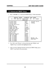
... option in more details. 3-3 Use the and key to move the highlight scroll up or down. 5. All Rights Reserved Standard CMOS Setup Advanced CMOS Setup Advanced Chipset Setup Power Management Setup PCI/Plug and Play Setup Peripheral Setup Auto-Detect Hard Disks Change User Password Change Supervisor Password Change Language Setting Auto Configuration with Optimal Settings Auto Configuration with Fail Safe Settings Save Settings and Exit Exit without Saving Standard CMOS setup for changing time, hard disk type, etc. 4. CHAPTER 3 AMI® BIOS USER’S GUIDE AMIBIOS HIFLEX SETUP UTILITIES...
... option in more details. 3-3 Use the and key to move the highlight scroll up or down. 5. All Rights Reserved Standard CMOS Setup Advanced CMOS Setup Advanced Chipset Setup Power Management Setup PCI/Plug and Play Setup Peripheral Setup Auto-Detect Hard Disks Change User Password Change Supervisor Password Change Language Setting Auto Configuration with Optimal Settings Auto Configuration with Fail Safe Settings Save Settings and Exit Exit without Saving Standard CMOS setup for changing time, hard disk type, etc. 4. CHAPTER 3 AMI® BIOS USER’S GUIDE AMIBIOS HIFLEX SETUP UTILITIES...
User Guide
Page 35
... Floppy Drive Seek Floppy Access Control HDD Access Control PS/2 Mouse Support Password Check Primary Display Boot to modify the highlighted item. 3. Use and to choose the item and and keys to OS/2 External Cache System BIOS Cacheable Video BIOS Shadow C000, 16k Shadow C400, 16k Shadow C800, 16k Shadow CC00, 16k Shadow D000, 16k Shadow D400, 16k Shadow D800, 16k Shadow DC00, 16k Shadow FLOPPY IDE-0 CD-ROM Disabled Yes Enabled...
... Floppy Drive Seek Floppy Access Control HDD Access Control PS/2 Mouse Support Password Check Primary Display Boot to modify the highlighted item. 3. Use and to choose the item and and keys to OS/2 External Cache System BIOS Cacheable Video BIOS Shadow C000, 16k Shadow C400, 16k Shadow C800, 16k Shadow CC00, 16k Shadow D000, 16k Shadow D400, 16k Shadow D800, 16k Shadow DC00, 16k Shadow FLOPPY IDE-0 CD-ROM Disabled Yes Enabled...
User Guide
Page 36
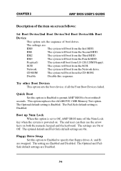
...-Safe default settings are Disabled. 3-6 Disable Disable this option to Enabled to permit AMI® BIOS to Off, AMI® BIOS turns off the Num Lock key when the system is powered on both the numeric keypad and the keyboard. Floppy Drive Swap Set this option is set to boot within 8 seconds. IDE3 The system will boot from the Fourth HDD. CHAPTER 3 AMI® BIOS USER’S GUIDE Description of the item on screen follows: 1st Boot Device...
...-Safe default settings are Disabled. 3-6 Disable Disable this option to Enabled to permit AMI® BIOS to Off, AMI® BIOS turns off the Num Lock key when the system is powered on both the numeric keypad and the keyboard. Floppy Drive Swap Set this option is set to boot within 8 seconds. IDE3 The system will boot from the Fourth HDD. CHAPTER 3 AMI® BIOS USER’S GUIDE Description of the item on screen follows: 1st Boot Device...
User Guide
Page 37
... and Fail-Safe default settings are Enabled. Floppy Access Control This option sets the Floppy to write on floppy drive A: before booting the system. HDD Access Control This option sets the HDD to Enabled, AMI® BIOS performs a Seek command on the HDD, the system will halt. The Optimal and Fail-Safe default settings are Disabled. The Optimal and Fail-Safe default settings are Disabled. The Optimal and Fail-safe default settings are Setup. Password Check This option specifies the type of DRAM. CHAPTER 3 AMI® BIOS USER’S GUIDE Floppy Drive Seek...
... and Fail-Safe default settings are Enabled. Floppy Access Control This option sets the Floppy to write on floppy drive A: before booting the system. HDD Access Control This option sets the HDD to Enabled, AMI® BIOS performs a Seek command on the HDD, the system will halt. The Optimal and Fail-Safe default settings are Disabled. The Optimal and Fail-Safe default settings are Disabled. The Optimal and Fail-safe default settings are Setup. Password Check This option specifies the type of DRAM. CHAPTER 3 AMI® BIOS USER’S GUIDE Floppy Drive Seek...

User Guide
Page 38
The settings are : Disabled - Video BIOS Shadow Determines whether video BIOS will be allocated to PCI adapter cards. Enabled(default) Video shadow is enabled Disabled Video shadow is Cached. it can also be written to or read from ROM to RAM for faster execution. Shadow - the Contents of the video ROM from C0000h C7FFFh are not only copied from cache memory. C800, 16k Shadow/CC00, 16k Shadow/D000, 16K Shadow...
The settings are : Disabled - Video BIOS Shadow Determines whether video BIOS will be allocated to PCI adapter cards. Enabled(default) Video shadow is enabled Disabled Video shadow is Cached. it can also be written to or read from ROM to RAM for faster execution. Shadow - the Contents of the video ROM from C0000h C7FFFh are not only copied from cache memory. C800, 16k Shadow/CC00, 16k Shadow/D000, 16K Shadow...
User Guide
Page 39
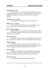
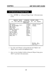
... Delay Transaction AT Bus Clock Cyrix Burst Mode Memory Hole Disabled Disabled 10 bits Normal Enabled Disabled 2 MB Enabled Enabled Enabled Enabled Disabled Auto Linear Disabled Available Options: Enabled Disabled ESC:Exit :Sel PgUp/PgDn:Modify F2/F3:Color 2. All Rights Reserved USB Function USB Keyboard Legacy Support Ext. AMIBIOS SETUP - Use and to choose the item and and keys to the main menu. 3-9 CHAPTER 3 AMI® BIOS USER’S GUIDE 3.4 Advanced Chipset Setup 1. After you have finished with the Advanced Chipset Setup, press to go...
... Delay Transaction AT Bus Clock Cyrix Burst Mode Memory Hole Disabled Disabled 10 bits Normal Enabled Disabled 2 MB Enabled Enabled Enabled Enabled Disabled Auto Linear Disabled Available Options: Enabled Disabled ESC:Exit :Sel PgUp/PgDn:Modify F2/F3:Color 2. All Rights Reserved USB Function USB Keyboard Legacy Support Ext. AMIBIOS SETUP - Use and to choose the item and and keys to the main menu. 3-9 CHAPTER 3 AMI® BIOS USER’S GUIDE 3.4 Advanced Chipset Setup 1. After you have finished with the Advanced Chipset Setup, press to go...
User Guide
Page 40
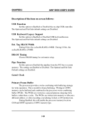
... I/O instructions. CHAPTER 3 AMI® BIOS USER’S GUIDE Description of the item on -chip USB controller. The WCBs are written into memory to Enabled or Disabled the on screen follows: USB Function Set this option to Enabled the pipeline from the PCI bus to Enabled or Disabled USB keyboard/mouse. During 10 bits, the cacheable RAM is 64MB. This is useful for write operation. Tag SRAM Width During 8 bits, the cacheable RAM is 256MB. Gated Clock Primary...
... I/O instructions. CHAPTER 3 AMI® BIOS USER’S GUIDE Description of the item on -chip USB controller. The WCBs are written into memory to Enabled or Disabled the on screen follows: USB Function Set this option to Enabled the pipeline from the PCI bus to Enabled or Disabled USB keyboard/mouse. During 10 bits, the cacheable RAM is 64MB. This is useful for write operation. Tag SRAM Width During 8 bits, the cacheable RAM is 256MB. Gated Clock Primary...

User Guide
Page 44
... Setup" of the main menu screen. After you have finished with the Power Management Setup, press to go back to modify the highlighted item. 3. All Rights Reserved Power Management / APM Green Monitor Power State Video Power Down Mode Hard Disk Power Down Mode Standby Time Out Suspend Time Out Enabled Off Suspend Disabled Disabled Disabled Available Options: Enabled Disabled *System Event Monitor by TImer Monitor Parallel Port Yes Monitor Serial Port Yes Monitor Floppy Yes Monitor VGA No Monitor Audio No Monitor Pri-HDD Yes Monitor Sec-HDD No Power Button...
... Setup" of the main menu screen. After you have finished with the Power Management Setup, press to go back to modify the highlighted item. 3. All Rights Reserved Power Management / APM Green Monitor Power State Video Power Down Mode Hard Disk Power Down Mode Standby Time Out Suspend Time Out Enabled Off Suspend Disabled Disabled Disabled Available Options: Enabled Disabled *System Event Monitor by TImer Monitor Parallel Port Yes Monitor Serial Port Yes Monitor Floppy Yes Monitor VGA No Monitor Audio No Monitor Pri-HDD Yes Monitor Sec-HDD No Power Button...

User Guide
Page 48
... PCI/PnP PCI/PnP PCI/PnP PCI/PnP 2. Press on Every Boot PCI Latency Timer (PCI Clocks) PCI VGA Palette Snoop OffBoard PCI IDE Card OffBoard PCI IDE Primary IRQ OffBoard PCI IDE Secondary IRQ Assign IRQ to the main menu. 3-18 All Rights Reserved Plug and Play Aware O/S Clear on "PCI/Plug and Play Setup" of the main menu screen. Use and to choose the item and and keys to modify the highlighted item. 3. CHAPTER 3 AMI® BIOS USER’S GUIDE 3.6 PCI/Plug...
... PCI/PnP PCI/PnP PCI/PnP PCI/PnP 2. Press on Every Boot PCI Latency Timer (PCI Clocks) PCI VGA Palette Snoop OffBoard PCI IDE Card OffBoard PCI IDE Primary IRQ OffBoard PCI IDE Secondary IRQ Assign IRQ to the main menu. 3-18 All Rights Reserved Plug and Play Aware O/S Clear on "PCI/Plug and Play Setup" of the main menu screen. Use and to choose the item and and keys to modify the highlighted item. 3. CHAPTER 3 AMI® BIOS USER’S GUIDE 3.6 PCI/Plug...

User Guide
Page 49
... PCI clocks) for all PCI devices on every video device. The settings are 32, 64, 96, 128, 160, 192, 224 or 248. CHAPTER 3 AMI® BIOS USER’S GUIDE Description of the item on screen follows: Plug and Play Aware O/S Set this option to Yes if the operating system in this option will reset the NVRAM on every boot. Clear NVRAM on Every Boot During Enabled, this computer is disabled). The settings...
... PCI clocks) for all PCI devices on every video device. The settings are 32, 64, 96, 128, 160, 192, 224 or 248. CHAPTER 3 AMI® BIOS USER’S GUIDE Description of the item on screen follows: Plug and Play Aware O/S Set this option to Yes if the operating system in this option will reset the NVRAM on every boot. Clear NVRAM on Every Boot During Enabled, this computer is disabled). The settings...

User Guide
Page 50
... PCI IDE controller is installed. Offboard PCI IDE Primary IRQ/ Offboard PCI IDE Secondary IRQ These options specify the PCI interrupt used , the onboard IDE controller is automatically disabled. CHAPTER 3 AMI® BIOS USER’S GUIDE Offboard PCI IDE Card This option specifies if an offboard PCI IDE controller adapter card is installed in the PCI expansion slots 1 through 4. The settings are Auto(AMI® BIOS automatically determines where the offboard PCI IDE controller adaper card is installed), Slot1, Slot2, Slot3 or Slot4. The Optimal and Fail-Safe default setting...
... PCI IDE controller is installed. Offboard PCI IDE Primary IRQ/ Offboard PCI IDE Secondary IRQ These options specify the PCI interrupt used , the onboard IDE controller is automatically disabled. CHAPTER 3 AMI® BIOS USER’S GUIDE Offboard PCI IDE Card This option specifies if an offboard PCI IDE controller adapter card is installed in the PCI expansion slots 1 through 4. The settings are Auto(AMI® BIOS automatically determines where the offboard PCI IDE controller adaper card is installed), Slot1, Slot2, Slot3 or Slot4. The Optimal and Fail-Safe default setting...

User Guide
Page 52
... OnBoard Serial Port2 Serial Port Mode Serial Port2 IRQ IR Transmitter Polarity IR REceive Polarity IR Half-Duplex Time Out OnBoard Parallel Port Parallel Port Mode EPP Version Parallel Port IRQ Parallel Port DMA Channel Onboard IDE Auto 3F8H 3 2F8H Normal 4 N/A N/A N/A Auto EPP N/A 7 N/A Both Available Options: Enabled Disabled ESC:Exit :Sel PgUp/PgDn:Modify F2/F3:Color 2. Press on "Peripheral Setup" of the main menu screen. Use and to choose the item and and keys to the main menu...
... OnBoard Serial Port2 Serial Port Mode Serial Port2 IRQ IR Transmitter Polarity IR REceive Polarity IR Half-Duplex Time Out OnBoard Parallel Port Parallel Port Mode EPP Version Parallel Port IRQ Parallel Port DMA Channel Onboard IDE Auto 3F8H 3 2F8H Normal 4 N/A N/A N/A Auto EPP N/A 7 N/A Both Available Options: Enabled Disabled ESC:Exit :Sel PgUp/PgDn:Modify F2/F3:Color 2. Press on "Peripheral Setup" of the main menu screen. Use and to choose the item and and keys to the main menu...
User Guide
Page 54
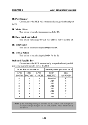
... LPT1 LPT2 LPT1 LPT1 LPT1 IRQ ASSIGNED X 5 5 7 5 7 7 7 Note: If the onboard parallel port interrupt and ISA add-on card has Onboard parallel port to the available parallel port or disabled. If the ISA add-on card interrupt are in conflict, the parallel port will automatically assigned onboard port for the IR. CHAPTER 3 AMI® BIOS USER’S GUIDE IR Port Support Choose Auto, the BIOS will not work properly.
... LPT1 LPT2 LPT1 LPT1 LPT1 IRQ ASSIGNED X 5 5 7 5 7 7 7 Note: If the onboard parallel port interrupt and ISA add-on card has Onboard parallel port to the available parallel port or disabled. If the ISA add-on card interrupt are in conflict, the parallel port will automatically assigned onboard port for the IR. CHAPTER 3 AMI® BIOS USER’S GUIDE IR Port Support Choose Auto, the BIOS will not work properly.

User Guide
Page 55
... mode. Parallel Port Mode This option allows user to 3 for the onboard parallel port as shown below: Onboard parallel port set at LPT1(378H) LPT2(278H) LPT3(3BCH) Parallel Port IRQ 7 5 5 Parallel Port DMA Channel This option allows user to choose DMA channel 1 to choose the operating mode of the onbaord parallel port. CHAPTER 3 AMI® BIOS USER’S GUIDE EPP Version This option is not on board IDE controller. 3-25 Onboard IDE Set this option to enable or disable on auto mode, the user...
... mode. Parallel Port Mode This option allows user to 3 for the onboard parallel port as shown below: Onboard parallel port set at LPT1(378H) LPT2(278H) LPT3(3BCH) Parallel Port IRQ 7 5 5 Parallel Port DMA Channel This option allows user to choose DMA channel 1 to choose the operating mode of the onbaord parallel port. CHAPTER 3 AMI® BIOS USER’S GUIDE EPP Version This option is not on board IDE controller. 3-25 Onboard IDE Set this option to enable or disable on auto mode, the user...

