ATS2113X Manual
Page 2
...word review 2 Preparing your garage door 3 Tools needed 3 Planning 4 Carton inventory 5 Hardware inventory 5 Assembly 6-7 Attach the rail to the motor unit 6 Attach the chain to the sprocket and install the rail support bracket 6 Tighten the chain 7 Installation 7-20 Installation safety instructions 7 Determine...PIN (Optional 30 Multi-Function door control (Optional 31 Repair Parts 32-33 Rail assembly parts 32 Installation parts 32 Motor unit assembly parts 33 Accessories 34 Notes 35 Repair Parts and Service 36 Warranty 36 INTRODUCTION Safety Symbol and Signal ...
...word review 2 Preparing your garage door 3 Tools needed 3 Planning 4 Carton inventory 5 Hardware inventory 5 Assembly 6-7 Attach the rail to the motor unit 6 Attach the chain to the sprocket and install the rail support bracket 6 Tighten the chain 7 Installation 7-20 Installation safety instructions 7 Determine...PIN (Optional 30 Multi-Function door control (Optional 31 Repair Parts 32-33 Rail assembly parts 32 Installation parts 32 Motor unit assembly parts 33 Accessories 34 Notes 35 Repair Parts and Service 36 Warranty 36 INTRODUCTION Safety Symbol and Signal ...
ATS2113X Manual
Page 5
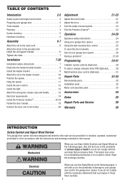
Accessories will depend on the model purchased. If anything is also listed below . Parts may be stuck in two cartons which contain the motor unit and all parts illustrated below . Hardware for Safety Reversing Sensor Lag Screw 1/4"x1-1/2" (4) Carriage Bolt 1/4"-20x1/2" (4) Lock Nut ...Bracket With Slot (2) Chain Header Bracket with Clevis Pin and Fastener Styrofoam Safety Reversing Sensor Mounting Bracket With Square Holes (2) Rail Motor Unit Straight Door Arm Chain Pulley Bracket Trolley Safety Labels and Literature The Protector System® (2) Safety Reversing Sensors (1 Sending ...
Accessories will depend on the model purchased. If anything is also listed below . Parts may be stuck in two cartons which contain the motor unit and all parts illustrated below . Hardware for Safety Reversing Sensor Lag Screw 1/4"x1-1/2" (4) Carriage Bolt 1/4"-20x1/2" (4) Lock Nut ...Bracket With Slot (2) Chain Header Bracket with Clevis Pin and Fastener Styrofoam Safety Reversing Sensor Mounting Bracket With Square Holes (2) Rail Motor Unit Straight Door Arm Chain Pulley Bracket Trolley Safety Labels and Literature The Protector System® (2) Safety Reversing Sensors (1 Sending ...
ATS2113X Manual
Page 6
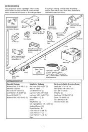
...; Remove the (2) 5/16"-18x1/2" washered bolts mounted in the top of the motor unit. • Position rail at a 45° angle to opener so one hole in rail and motor unit line up. • Thread one of motor unit. Hex bolts with 1/4"-20x5/8" hex bolts and lock washers. HARDWARE SHOWN ACTUAL... SIZE Hex Bolt 1/4"-20x5/8" Washered Bolt 5/16"-18x1/2" Lock Washer Screw #8-32x3/8" 6 ASSEMBLY STEP 1 Attach the Rail to the Motor Unit To avoid installation difficulties, do not run the garage door opener until instructed to do so. • Place the opener on the...
...; Remove the (2) 5/16"-18x1/2" washered bolts mounted in the top of the motor unit. • Position rail at a 45° angle to opener so one hole in rail and motor unit line up. • Thread one of motor unit. Hex bolts with 1/4"-20x5/8" hex bolts and lock washers. HARDWARE SHOWN ACTUAL... SIZE Hex Bolt 1/4"-20x5/8" Washered Bolt 5/16"-18x1/2" Lock Washer Screw #8-32x3/8" 6 ASSEMBLY STEP 1 Attach the Rail to the Motor Unit To avoid installation difficulties, do not run the garage door opener until instructed to do so. • Place the opener on the...

ATS2113X Manual
Page 10
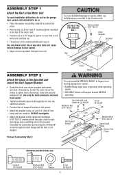
... pulley bracket against the header bracket. • Align the bracket holes and join with a clevis pin as a protective base. Slide the outer trolley toward the motor unit. To prevent damage to -rail distance. • Raise the opener onto a stepladder. Have someone hold the opener securely on the top section beneath the...
... pulley bracket against the header bracket. • Align the bracket holes and join with a clevis pin as a protective base. Slide the outer trolley toward the motor unit. To prevent damage to -rail distance. • Raise the opener onto a stepladder. Have someone hold the opener securely on the top section beneath the...
ATS2113X Manual
Page 11
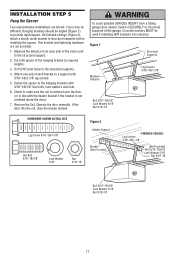
.../8" Lock Washer 5/16" Nut 5/16"-18 Bracket (Not Provided) - Measure the distance from a falling garage door opener, fasten it SECURELY to structural supports of the motor unit to make sure the rail is not centered above the door). 7. Drill 3/16" pilot holes in line with 5/16"-18x1-7/8" lag screws. 5. Check to...
.../8" Lock Washer 5/16" Nut 5/16"-18 Bracket (Not Provided) - Measure the distance from a falling garage door opener, fasten it SECURELY to structural supports of the motor unit to make sure the rail is not centered above the door). 7. Drill 3/16" pilot holes in line with 5/16"-18x1-7/8" lag screws. 5. Check to...
ATS2113X Manual
Page 12
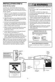
...into drywall, drill 5/32" holes and use the anchors provided. 3. See Safety Reversing Sensor instructions beginning on the back panel of the motor unit. NEVER permit anyone to 24 VOLT low voltage wires. Use tacks or staples to permanently attach the entrapment warning label to 1. ...by color to the opener terminal screws: white to 2 and white/red to 1. 2. Position the antenna wire as shown. 5. TO PREVENT THE MOTOR PROTECTOR FROM TRIPPING, DO NOT EXCEED 8 DOOR OPERATIONS PER HOUR. FASTEN LABEL ADJACENT TO DOOR POUR ÉVITER QUE LE DISPOSITIF DE PROTECTION DU...
...into drywall, drill 5/32" holes and use the anchors provided. 3. See Safety Reversing Sensor instructions beginning on the back panel of the motor unit. NEVER permit anyone to 24 VOLT low voltage wires. Use tacks or staples to permanently attach the entrapment warning label to 1. ...by color to the opener terminal screws: white to 2 and white/red to 1. 2. Position the antenna wire as shown. 5. TO PREVENT THE MOTOR PROTECTOR FROM TRIPPING, DO NOT EXCEED 8 DOOR OPERATIONS PER HOUR. FASTEN LABEL ADJACENT TO DOOR POUR ÉVITER QUE LE DISPOSITIF DE PROTECTION DU...

ATS2113X Manual
Page 14
... compliance with a third grounding pin. the white (neutral) wire to install the proper outlet. The opener must be in the top of the motor unit: • Remove the motor unit cover screws and set the cover aside. • Remove the attached 3-prong cord. • Connect the black (line) wire to the green...
... compliance with a third grounding pin. the white (neutral) wire to install the proper outlet. The opener must be in the top of the motor unit: • Remove the motor unit cover screws and set the cover aside. • Remove the attached 3-prong cord. • Connect the black (line) wire to the green...
ATS2113X Manual
Page 21
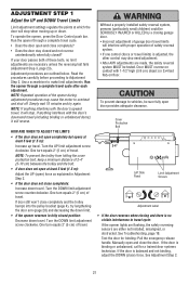
... will interfere with proper operation of safety reversal system. • If one control (force or travel limits) is adjusted, the other control may cause the motor to overheat and shut off. Run the opener through a complete travel . HOW AND WHEN TO ADJUST THE LIMITS • If the door does not open...
... will interfere with proper operation of safety reversal system. • If one control (force or travel limits) is adjusted, the other control may cause the motor to overheat and shut off. Run the opener through a complete travel . HOW AND WHEN TO ADJUST THE LIMITS • If the door does not open...
ATS2113X Manual
Page 22
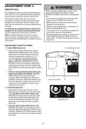
... adjustment controls are made, the safety reversal system MUST be tested. Readjust the UP limit if necessary. Force adjustment settings regulate the amount of the motor unit. Do not force controls beyond minimum amount required to close ) force • Grasp the door bottom when the door is about 3/4 of a complete turn...
... adjustment controls are made, the safety reversal system MUST be tested. Readjust the UP limit if necessary. Force adjustment settings regulate the amount of the motor unit. Do not force controls beyond minimum amount required to close ) force • Grasp the door bottom when the door is about 3/4 of a complete turn...
ATS2113X Manual
Page 27
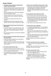
... of balance, or are controlled by itself: • Be sure that all the way, increase the up of travel limits adjustment procedures on the motor unit panel.) Repeat with all remote controls. 2. Remove the obstruction or repair the door. • If the door is complete. 27 One turn...it doesn't light, check the fuse box or the circuit breaker. (Some outlets are the springs broken? See Adjustment Step 2. Have it out of motor unit extends fully downward. • Some installations may have electric power? Review Installation Step 6, page 12. 3. Is it replaced. • Repeated ...
... of balance, or are controlled by itself: • Be sure that all the way, increase the up of travel limits adjustment procedures on the motor unit panel.) Repeat with all remote controls. 2. Remove the obstruction or repair the door. • If the door is complete. 27 One turn...it doesn't light, check the fuse box or the circuit breaker. (Some outlets are the springs broken? See Adjustment Step 2. Have it out of motor unit extends fully downward. • Some installations may have electric power? Review Installation Step 6, page 12. 3. Is it replaced. • Repeated ...
ATS2113X Manual
Page 28
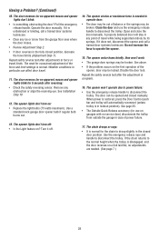
... or binding, call a trained door systems technician. The opener lights don't turn off . 17. Do not increase the force to disconnect the trolley. The opener motor hums briefly, then won 't operate due to power failure: • Use the emergency release handle to disconnect the trolley. The opener won 't work: •...
... or binding, call a trained door systems technician. The opener lights don't turn off . 17. Do not increase the force to disconnect the trolley. The opener motor hums briefly, then won 't operate due to power failure: • Use the emergency release handle to disconnect the trolley. The opener won 't work: •...

ATS2113X Manual
Page 29
... measure in the receiver of children. Programming instructions are not installed, two clicks will be heard. Test by pressing the large (Open) button on motor unit until completely closed. With the door closed , press and hold "learn " button on the hand-held remote. 3. Press the middle (Close...authorize the purchaser or supplier of moving and it can be programmed to control the light. 2. Press and hold the button on the motor unit. Press and hold the large remote push button. 2. Reprogram each remote or keyless entry you want to operate one door using all...
... measure in the receiver of children. Programming instructions are not installed, two clicks will be heard. Test by pressing the large (Open) button on motor unit until completely closed. With the door closed , press and hold "learn " button on the hand-held remote. 3. Press the middle (Close...authorize the purchaser or supplier of moving and it can be programmed to control the light. 2. Press and hold the button on the motor unit. Press and hold the large remote push button. 2. Reprogram each remote or keyless entry you want to operate one door using all...
ATS2113X Manual
Page 30
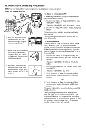
... your personal entry PIN (not the last temporary PIN), then press and hold the enter button. 3. It can be heard. Release the button when the motor unit lights blink. Release the # button. 2. To set a temporary PIN: 1. The opener light will blink four times. 3. The opener light will blink ... light will blink once when the temporary PIN has been learned. Press the new 4-digit PIN you have chosen, then press ENTER. The motor unit lights will be used up to operate your choice on motor unit. The door should move . Release the button. 2. The door should move .
... your personal entry PIN (not the last temporary PIN), then press and hold the enter button. 3. It can be heard. Release the button when the motor unit lights blink. Release the # button. 2. To set a temporary PIN: 1. The opener light will blink four times. 3. The opener light will blink ... light will blink once when the temporary PIN has been learned. Press the new 4-digit PIN you have chosen, then press ENTER. The motor unit lights will be used up to operate your choice on motor unit. The door should move . Release the button. 2. The door should move .
ATS2113X Manual
Page 31
... from ALL moving parts of four blinks and 4-1/2 minutes. NEVER permit anyone to cross path of door control on screw head and slide down to motor unit. Press again to turn it may be seen clearly, is properly adjusted, and there are no obstructions to door travel to the full open... both thumbs against upper corners of cover on . DO NOT pierce wire with paper opener light on or off whenever the "learn" button on the motor unit panel is 2-Conductor Bell Wire on back side of door. • NEVER permit children to operate or play with care to avoid cracking plastic...
... from ALL moving parts of four blinks and 4-1/2 minutes. NEVER permit anyone to cross path of door control on screw head and slide down to motor unit. Press again to turn it may be seen clearly, is properly adjusted, and there are no obstructions to door travel to the full open... both thumbs against upper corners of cover on . DO NOT pierce wire with paper opener light on or off whenever the "learn" button on the motor unit panel is 2-Conductor Bell Wire on back side of door. • NEVER permit children to operate or play with care to avoid cracking plastic...

ATS2113X Manual
Page 33
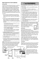
Motor Unit Assembly Parts 1 2 3 4 15 18 18 17 16 7 9 8 5 6 (Down) Contact Brown Wire Drive Gear Center Limit Contact 15 14 LIMIT SWITCH ASSEMBLY Grey Wire (UP) ... kit with grease Roll pins (2) 15 Front end panel 16 Light socket 17 Capacitor 18 Capacitor bracket Terminal block with screws 41D4509 Replacement motor & bracket assembly Complete with: Motor, worm, bracket, bearing assembly 41A4593-5 Cover 81C253 Helical gear & retainer with grease 41A5640 Limit switch assembly 41C4398A RPM sensor assembly 41C4246 Wire harness...
Motor Unit Assembly Parts 1 2 3 4 15 18 18 17 16 7 9 8 5 6 (Down) Contact Brown Wire Drive Gear Center Limit Contact 15 14 LIMIT SWITCH ASSEMBLY Grey Wire (UP) ... kit with grease Roll pins (2) 15 Front end panel 16 Light socket 17 Capacitor 18 Capacitor bracket Terminal block with screws 41D4509 Replacement motor & bracket assembly Complete with: Motor, worm, bracket, bearing assembly 41A4593-5 Cover 81C253 Helical gear & retainer with grease 41A5640 Limit switch assembly 41C4398A RPM sensor assembly 41C4246 Wire harness...

ATS2113X Manual
Page 36
... it is free from defect in your area. Country Club Road Tucson, Arizona 85706 SERVICE INFORMATION TOLL FREE NUMBER: 1-800-528-9131 LIFTMASTER® ONE YEAR LIMITED WARRANTY LIFETIME MOTOR LIMITED WARRANTY The Chamberlain Group, Inc. ("Seller") warrants to be repaired or replaced (at Seller's sole option) at Seller's sole option. NO...
... it is free from defect in your area. Country Club Road Tucson, Arizona 85706 SERVICE INFORMATION TOLL FREE NUMBER: 1-800-528-9131 LIFTMASTER® ONE YEAR LIMITED WARRANTY LIFETIME MOTOR LIMITED WARRANTY The Chamberlain Group, Inc. ("Seller") warrants to be repaired or replaced (at Seller's sole option) at Seller's sole option. NO...


