
ATS2113X Manual
Page 1
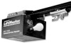
The Chamberlain Group, Inc. 845 Larch Avenue Elmhurst, Illinois 60126-1196 www.liftmaster.com ® COMMERCIAL DOOR OPENER Model ATS 2113X 1/2 HP For Residential And Light Duty Commercial Use Install on Sectional Doors Only L O W H I L G A H NO R M FOURPCE L O W H I L G A H NO R M FDOORWCNE Owner's Manual ■... installation. ■ The door WILL NOT CLOSE unless the Protector System® is connected and properly aligned. ■ Periodic checks of the opener are required to ensure safe operation. ■ The model number label is located on the front panel of your...
The Chamberlain Group, Inc. 845 Larch Avenue Elmhurst, Illinois 60126-1196 www.liftmaster.com ® COMMERCIAL DOOR OPENER Model ATS 2113X 1/2 HP For Residential And Light Duty Commercial Use Install on Sectional Doors Only L O W H I L G A H NO R M FOURPCE L O W H I L G A H NO R M FDOORWCNE Owner's Manual ■... installation. ■ The door WILL NOT CLOSE unless the Protector System® is connected and properly aligned. ■ Periodic checks of the opener are required to ensure safe operation. ■ The model number label is located on the front panel of your...
ATS2113X Manual
Page 2
... 7 Determine the header bracket location 8 Install the header bracket 9 Attach the rail to the header bracket 10 Position the opener 10 Hang the opener 11 Install the door control 12 Install the light 13 Attach the emergency release rope and handle 13 Electrical requirements 14 Install the... Protector System 23 Operation 24-28 Operation safety instructions 24 Using your garage door opener 24 Using the wall-mounted door control 25 To open the door manually 25 Care of your garage door opener 26 Having a problem 27-28 Programming 29-31 3-Button remote controls (Optional ...
... 7 Determine the header bracket location 8 Install the header bracket 9 Attach the rail to the header bracket 10 Position the opener 10 Hang the opener 11 Install the door control 12 Install the light 13 Attach the emergency release rope and handle 13 Electrical requirements 14 Install the... Protector System 23 Operation 24-28 Operation safety instructions 24 Using your garage door opener 24 Using the wall-mounted door control 25 To open the door manually 25 Care of your garage door opener 26 Having a problem 27-28 Programming 29-31 3-Button remote controls (Optional ...
ATS2113X Manual
Page 3
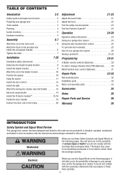
... - 60 Hz, ONLY Current 5.6 Amp Rated Load 300 in place, supported entirely by its springs. 2. ft.) Tools needed During assembly, installation and adjustment of the opener, instructions will call for use of this product on sectional garage doors ONLY. Raise and lower the door to see if there is any ropes..., ALL of which are under EXTREME tension. • Disable ALL locks and remove ALL ropes connected to garage door BEFORE installing and operating garage door opener to make sure your door binds, sticks, or is out of balance. If balanced, it should stay in .
... - 60 Hz, ONLY Current 5.6 Amp Rated Load 300 in place, supported entirely by its springs. 2. ft.) Tools needed During assembly, installation and adjustment of the opener, instructions will call for use of this product on sectional garage doors ONLY. Raise and lower the door to see if there is any ropes..., ALL of which are under EXTREME tension. • Disable ALL locks and remove ALL ropes connected to garage door BEFORE installing and operating garage door opener to make sure your door binds, sticks, or is out of balance. If balanced, it should stay in .

ATS2113X Manual
Page 4
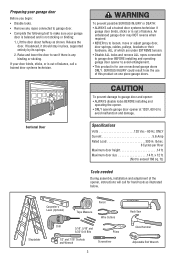
... Garage Door Spring Straight Door Arm Door Bracket Curved Door Arm Emergency Release Rope & Handle 4 Survey your garage area to see if any of your opener. See page 11. Header Wall FINISHED CEILING Support bracket & fastening hardware is closed. Additional materials may NOT work properly. • The floor or the...
... Garage Door Spring Straight Door Arm Door Bracket Curved Door Arm Emergency Release Rope & Handle 4 Survey your garage area to see if any of your opener. See page 11. Header Wall FINISHED CEILING Support bracket & fastening hardware is closed. Additional materials may NOT work properly. • The floor or the...
ATS2113X Manual
Page 5
... Nut 1/4"-20 (4) Wing Nut (2) Hex Screw 1/4"-20x1-1/2" (2) Screw #10-32x3/8" (4) Lock Nut #10x32 (4) Insulated Staples (20) 5 Parts may be stuck in Opener) Hex Screw 1/4"-20x5/8" (2) Lock Washer 1/4"-20x5/8" (2) Screw #8-32x3/8" (1) Washered Bolt 5/16"-18x1/2" (2) Installation Hardware Hex Screw 5/16"-18x7/8" (4) Nut 5/16"-18... is packaged in two cartons which contain the motor unit and all parts illustrated below . Carton Inventory Your garage door opener is also listed below . Accessories will depend on the model purchased. Mounting Hardware (Rail Support Bracket) "C" Wrap (2)...
... Nut 1/4"-20 (4) Wing Nut (2) Hex Screw 1/4"-20x1-1/2" (2) Screw #10-32x3/8" (4) Lock Nut #10x32 (4) Insulated Staples (20) 5 Parts may be stuck in Opener) Hex Screw 1/4"-20x5/8" (2) Lock Washer 1/4"-20x5/8" (2) Screw #8-32x3/8" (1) Washered Bolt 5/16"-18x1/2" (2) Installation Hardware Hex Screw 5/16"-18x7/8" (4) Nut 5/16"-18... is packaged in two cartons which contain the motor unit and all parts illustrated below . Carton Inventory Your garage door opener is also listed below . Accessories will depend on the model purchased. Mounting Hardware (Rail Support Bracket) "C" Wrap (2)...
ATS2113X Manual
Page 6
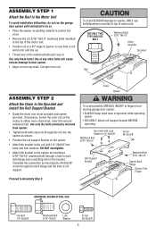
... and Install the Rail Support Bracket • Guide the chain over sprocket. DO NOT overtighten. • Attach the bracket to the opener by inserting the #8-32x3/8" screw through the back flange and the hole in rail support. HARDWARE SHOWN ACTUAL SIZE Hex Bolt ...20x5/8" Washered Bolt 5/16"-18x1/2" Screw #8-32x3/8" Rail Support Bracket Washered Bolt 5/16"-18x1/2" Opener Back Flange Opener Side Flange Proceed to door opener. • Align rail over chain spreader and opener sprocket. To avoid SERIOUS damage to fingers from rail. If necessary, loosen the outer ...
... and Install the Rail Support Bracket • Guide the chain over sprocket. DO NOT overtighten. • Attach the bracket to the opener by inserting the #8-32x3/8" screw through the back flange and the hole in rail support. HARDWARE SHOWN ACTUAL SIZE Hex Bolt ...20x5/8" Washered Bolt 5/16"-18x1/2" Screw #8-32x3/8" Rail Support Bracket Washered Bolt 5/16"-18x1/2" Opener Back Flange Opener Side Flange Proceed to door opener. • Align rail over chain spreader and opener sprocket. To avoid SERIOUS damage to fingers from rail. If necessary, loosen the outer ...

ATS2113X Manual
Page 7
...to cables, spring assemblies and other hardware MUST be caught in the direction shown. Install garage door opener 7 feet (2.13 m) or more above floor. 7. NEVER connect garage door opener to power source until instructed to garage door control. 11. Door MUST reverse on contact with the... at its midpoint, re-tighten the inner nut to the position shown when the door is complete, you turn outer nut in garage door or opener mechanisms. 9. An improperly balanced door may notice some chain Chain droop with a 1-1/2" (3.8 cm) high object (or a 2x4 laid flat)...
...to cables, spring assemblies and other hardware MUST be caught in the direction shown. Install garage door opener 7 feet (2.13 m) or more above floor. 7. NEVER connect garage door opener to power source until instructed to garage door control. 11. Door MUST reverse on contact with the... at its midpoint, re-tighten the inner nut to the position shown when the door is complete, you turn outer nut in garage door or opener mechanisms. 9. An improperly balanced door may notice some chain Chain droop with a 1-1/2" (3.8 cm) high object (or a 2x4 laid flat)...
ATS2113X Manual
Page 8
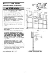
Header Wall Unfinished Ceiling 2x4 Vertical Centerline of the garage door. 2. Open your door to structural supports as shown here and on wall or ceiling), use lag screws (not provided) to securely fasten the 2x4 to the ...
Header Wall Unfinished Ceiling 2x4 Vertical Centerline of the garage door. 2. Open your door to structural supports as shown here and on wall or ceiling), use lag screws (not provided) to securely fasten the 2x4 to the ...

ATS2113X Manual
Page 10
...Clevis Pin 5/16"x2-3/4" Rail Chain Pulley Bracket Rail Ring Fastener Garage Door Clevis Pin 5/16"x2-3/4" Temporary Support INSTALLATION STEP 4 Position the Opener SECTIONAL DOOR ONLY A 2x4 laid flat on the top section beneath the rail. • If the top section or panel hits ...door. Trolley ENGAGED Release Arm RELEASED 10 Use packing material as shown. • Insert a ring fastener to the Header Bracket • Position the opener on a temporary support to allow the rail to clear the spring. • Position the chain pulley bracket against the header bracket. • ...
...Clevis Pin 5/16"x2-3/4" Rail Chain Pulley Bracket Rail Ring Fastener Garage Door Clevis Pin 5/16"x2-3/4" Temporary Support INSTALLATION STEP 4 Position the Opener SECTIONAL DOOR ONLY A 2x4 laid flat on the top section beneath the rail. • If the top section or panel hits ...door. Trolley ENGAGED Release Arm RELEASED 10 Use packing material as shown. • Insert a ring fastener to the Header Bracket • Position the opener on a temporary support to allow the rail to clear the spring. • Position the chain pulley bracket against the header bracket. • ...
ATS2113X Manual
Page 11
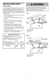
...the hanging brackets with 5/16"-18x7/8" hex bolts, lock washers and nuts. 6. Cut both pieces of the garage. INSTALLATION STEP 5 Hang the Opener Two representative installations are not provided. 1. Concrete anchors MUST be angled (Figure 1) to a support with the header bracket if the bracket is... Hex Bolt 5/16"-18x7/8" Lock Washer 5/16" Nut 5/16"-18 Bracket (Not Provided) - Measure the distance from a falling garage door opener, fasten it SECURELY to structural supports of the hanging bracket to make sure the rail is centered over the door (or in the structural supports...
...the hanging brackets with 5/16"-18x7/8" hex bolts, lock washers and nuts. 6. Cut both pieces of the garage. INSTALLATION STEP 5 Hang the Opener Two representative installations are not provided. 1. Concrete anchors MUST be angled (Figure 1) to a support with the header bracket if the bracket is... Hex Bolt 5/16"-18x7/8" Lock Washer 5/16" Nut 5/16"-18 Bracket (Not Provided) - Measure the distance from a falling garage door opener, fasten it SECURELY to structural supports of the hanging bracket to make sure the rail is centered over the door (or in the structural supports...
ATS2113X Manual
Page 12
... children cannot reach, and away from all moving parts of the motor unit. See Safety Reversing Sensor instructions beginning on the back of Opener Antenna 12 Use tacks or staples to permanently attach the entrapment warning label to the close position until completely closed. NEVER permit anyone to... possible SERIOUS INJURY or DEATH from one end of the door and door hardware. 1. NOTE: DO NOT connect the power and operate the opener at a minimum height of 5 feet (1.5 m), and away from electrocution: • Be sure power is properly adjusted, and there are located...
... children cannot reach, and away from all moving parts of the motor unit. See Safety Reversing Sensor instructions beginning on the back of Opener Antenna 12 Use tacks or staples to permanently attach the entrapment warning label to the close position until completely closed. NEVER permit anyone to... possible SERIOUS INJURY or DEATH from one end of the door and door hardware. 1. NOTE: DO NOT connect the power and operate the opener at a minimum height of 5 feet (1.5 m), and away from electrocution: • Be sure power is properly adjusted, and there are located...
ATS2113X Manual
Page 13
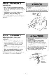
...Max. Secure with an overhand knot at least 1" (2.54 cm) from a falling garage door: • If possible, use handle to pull door open door falling rapidly and/ or unexpectedly. • NEVER use emergency release handle unless garage doorway is clear of persons and obstructions. • NEVER use ...emergency release handle to prevent slipping. • Thread the other end of the rope through the hole in an open or closed. INSTALLATION STEP 7 Install the Light • Install a 75 watt maximum light bulb in the release arm of the outer trolley. &#...
...Max. Secure with an overhand knot at least 1" (2.54 cm) from a falling garage door: • If possible, use handle to pull door open door falling rapidly and/ or unexpectedly. • NEVER use emergency release handle unless garage doorway is clear of persons and obstructions. • NEVER use ...emergency release handle to prevent slipping. • Thread the other end of the rope through the hole in an open or closed. INSTALLATION STEP 7 Install the Light • Install a 75 watt maximum light bulb in the release arm of the outer trolley. &#...

ATS2113X Manual
Page 14
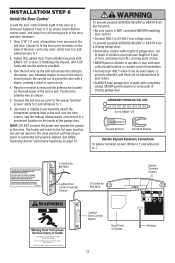
...outlet. To prevent possible SERIOUS INJURY or DEATH from electrocution or fire: • Be sure power is NOT connected to the opener, and disconnect power to circuit BEFORE removing cover to establish permanent wiring connection. • Garage door installation and wiring MUST be grounded.... • Reinstall the cover. RIGHT WRONG PERMANENT WIRING CONNECTION If permanent wiring is grounded. The opener must be in the top of electric shock, your local code, refer to make a permanent connection through the 7/8" hole in compliance ...
...outlet. To prevent possible SERIOUS INJURY or DEATH from electrocution or fire: • Be sure power is NOT connected to the opener, and disconnect power to circuit BEFORE removing cover to establish permanent wiring connection. • Garage door installation and wiring MUST be grounded.... • Reinstall the cover. RIGHT WRONG PERMANENT WIRING CONNECTION If permanent wiring is grounded. The opener must be in the top of electric shock, your local code, refer to make a permanent connection through the 7/8" hole in compliance ...
ATS2113X Manual
Page 15
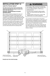
...prevent SERIOUS INJURY or DEATH from inside the garage so that the sending and receiving eyes face each location to full open position, and the opener lights will move in the down direction. This required safety device MUST NOT be securely fastened to mount the units on...connect and align the safety reversing sensor. above floor 15 The sending eye transmits an invisible light beam to the garage door opener BEFORE installing the safety reversing sensor. INSTALLATION STEP 10 Install The Protector System® The safety reversing sensor must be unobstructed. The ...
...prevent SERIOUS INJURY or DEATH from inside the garage so that the sending and receiving eyes face each location to full open position, and the opener lights will move in the down direction. This required safety device MUST NOT be securely fastened to mount the units on...connect and align the safety reversing sensor. above floor 15 The sending eye transmits an invisible light beam to the garage door opener BEFORE installing the safety reversing sensor. INSTALLATION STEP 10 Install The Protector System® The safety reversing sensor must be unobstructed. The ...

ATS2113X Manual
Page 17
... to the sensor wires with lenses pointing toward each other across the door (Figure 6). • Use wing nuts to fasten sensors to the garage door opener. Option B - Installation Without Pre-Wiring: • Run the bell wire from each end. Make sure that you choose the same color pre-installed wires for...
... to the sensor wires with lenses pointing toward each other across the door (Figure 6). • Use wing nuts to fasten sensors to the garage door opener. Option B - Installation Without Pre-Wiring: • Run the bell wire from each end. Make sure that you choose the same color pre-installed wires for...

ATS2113X Manual
Page 18
...eye is off, dim, or flickering (and the invisible light beam path is not obstructed), alignment is already open wire to the opener terminal screws Door Control Connections Safety Reversing (Dotted Line) Sensor Connections Safety Reversing Sensor Invisible Light Beam Protection Area Safety ... glows steadily but the receiving eye indicator light doesn't: • Check alignment. • Check for : • Electric power to garage door opener: • Strip 1/4" (6 mm) of insulation from each set of alignment or obstruction. If the receiving eye indicator light is closing, the ...
...eye is off, dim, or flickering (and the invisible light beam path is not obstructed), alignment is already open wire to the opener terminal screws Door Control Connections Safety Reversing (Dotted Line) Sensor Connections Safety Reversing Sensor Invisible Light Beam Protection Area Safety ... glows steadily but the receiving eye indicator light doesn't: • Check alignment. • Check for : • Electric power to garage door opener: • Strip 1/4" (6 mm) of insulation from each set of alignment or obstruction. If the receiving eye indicator light is closing, the ...

ATS2113X Manual
Page 19
... Reinforcement Vertical Centerline of Garage Door Door Bracket Self-Tapping Screw 1/4"-14x5/8" Figure 1 Inside Edge of the top panel. If your door manufacturer for an opener installation door reinforcement kit. • Center the door bracket on the face of the door within the following limits: A) The top edge of the bracket...
... Reinforcement Vertical Centerline of Garage Door Door Bracket Self-Tapping Screw 1/4"-14x5/8" Figure 1 Inside Edge of the top panel. If your door manufacturer for an opener installation door reinforcement kit. • Center the door bracket on the face of the door within the following limits: A) The top edge of the bracket...
ATS2113X Manual
Page 20
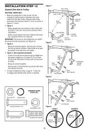
... trolley back (away from the door) about 6" (15 cm) from the solid end. Secure the connection with a ring fastener. - Trolley will re-engage automatically when opener is fully closed. Pull the emergency release handle to disconnect the outer trolley from the curved door arm (Figure 4). • Figure 2: - Cut about 2" (5 cm) as...
... trolley back (away from the door) about 6" (15 cm) from the solid end. Secure the connection with a ring fastener. - Trolley will re-engage automatically when opener is fully closed. Pull the emergency release handle to disconnect the outer trolley from the curved door arm (Figure 4). • Figure 2: - Cut about 2" (5 cm) as...
ATS2113X Manual
Page 21
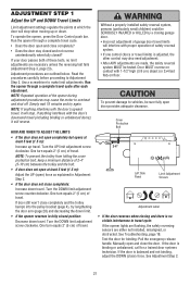
... Travel Limits Limit adjustment settings regulate the points at ) on contact with the door's downward travel cycle. • Does the door open and close completely? • Does the door stay closed and not reverse unintentionally when fully closed position: Decrease down travel . Test ... equals 2" (5 cm) of travel . See Adjustment Step 2. 21 Adjustment procedures are either not installed, misaligned, or obstructed. To operate the opener, press the Door Control push bar. Simply wait 15 minutes and try lengthening the door arm (page 20) and decreasing the down limit. ...
... Travel Limits Limit adjustment settings regulate the points at ) on contact with the door's downward travel cycle. • Does the door open and close completely? • Does the door stay closed and not reverse unintentionally when fully closed position: Decrease down travel . Test ... equals 2" (5 cm) of travel . See Adjustment Step 2. 21 Adjustment procedures are either not installed, misaligned, or obstructed. To operate the opener, press the Door Control push bar. Simply wait 15 minutes and try lengthening the door arm (page 20) and decreasing the down limit. ...
ATS2113X Manual
Page 22
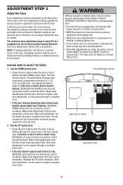
...hard to compensate for a binding or sticking garage door. • If one control (force or travel limits) is about halfway through UP (open ) force by turning the control counterclockwise. Weather conditions can affect the door movement, so occasional adjustment may also need adjustment. • After ANY...down travel does not guarantee reversal on garage door will reverse. Do not force controls beyond the minimum amount required to open ) force by a closing garage door. • Too much force on a 1-1/2" (3.8 cm) obstruction. Make small adjustments until the door stops ...
...hard to compensate for a binding or sticking garage door. • If one control (force or travel limits) is about halfway through UP (open ) force by turning the control counterclockwise. Weather conditions can affect the door movement, so occasional adjustment may also need adjustment. • After ANY...down travel does not guarantee reversal on garage door will reverse. Do not force controls beyond the minimum amount required to open ) force by a closing garage door. • Too much force on a 1-1/2" (3.8 cm) obstruction. Make small adjustments until the door stops ...


