
Owners Manual
Page 1
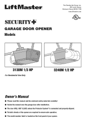
® GARAGE DOOR OPENER Models The Chamberlain Group, Inc. 845 Larch Avenue Elmhurst, Illinois 60126-1196 www.liftmaster.com 3130M 1/3 HP For Residential Use Only 3240M 1/2 HP Owner's Manual ■ Please read this manual and the enclosed safety materials carefully! ■ Fasten the manual near the garage door after installation. ■ The door WILL NOT CLOSE unless the Protector System® is connected and properly aligned. ■ Periodic checks of the opener are required to ensure safe operation. ■ The model number label is located on the front panel of your opener.
® GARAGE DOOR OPENER Models The Chamberlain Group, Inc. 845 Larch Avenue Elmhurst, Illinois 60126-1196 www.liftmaster.com 3130M 1/3 HP For Residential Use Only 3240M 1/2 HP Owner's Manual ■ Please read this manual and the enclosed safety materials carefully! ■ Fasten the manual near the garage door after installation. ■ The door WILL NOT CLOSE unless the Protector System® is connected and properly aligned. ■ Periodic checks of the opener are required to ensure safe operation. ■ The model number label is located on the front panel of your opener.
Owners Manual
Page 2
... the Protector System 25 Operation 26-30 Operation safety instructions 26 Using your garage door opener 26 Using the wall-mounted door control 27 To open the door manually 27 Care of your garage door opener 28 Having a problem 29 Diagnostic chart 30 Programming 31-32 To add ... Parts and Service Back page Warranty Back page INTRODUCTION Safety Symbol and Signal Word Review This garage door opener has been designed and tested to your garage door and/or the garage door opener if you do not comply with the cautionary statements that accompany them carefully. 2
... the Protector System 25 Operation 26-30 Operation safety instructions 26 Using your garage door opener 26 Using the wall-mounted door control 27 To open the door manually 27 Care of your garage door opener 28 Having a problem 29 Diagnostic chart 30 Programming 31-32 To add ... Parts and Service Back page Warranty Back page INTRODUCTION Safety Symbol and Signal Word Review This garage door opener has been designed and tested to your garage door and/or the garage door opener if you do not comply with the cautionary statements that accompany them carefully. 2
Owners Manual
Page 3
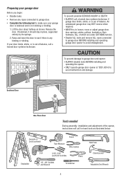
...Sockets and Wrench Screwdriver Hack Saw Claw Hammer Adjustable End Wrench 3 To prevent damage to garage door and opener: • ALWAYS disable locks BEFORE installing and operating the opener. • ONLY operate garage door opener at 120V, 60 Hz to see if there is not sticking or binding: 1. ...8226; Disable ALL locks and remove ALL ropes connected to garage door BEFORE installing and operating garage door opener to loosen, move or adjust garage door, door springs, cables, pulleys, brackets or their hardware, ALL of the opener, instructions will call for hand tools as shown. To ...
...Sockets and Wrench Screwdriver Hack Saw Claw Hammer Adjustable End Wrench 3 To prevent damage to garage door and opener: • ALWAYS disable locks BEFORE installing and operating the opener. • ONLY operate garage door opener at 120V, 60 Hz to see if there is not sticking or binding: 1. ...8226; Disable ALL locks and remove ALL ropes connected to garage door BEFORE installing and operating garage door opener to loosen, move or adjust garage door, door springs, cables, pulleys, brackets or their hardware, ALL of the opener, instructions will call for hand tools as shown. To ...
Owners Manual
Page 4
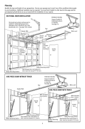
...panels, etc.). Rail Extension Torsion OR Spring Spring Motor unit Vertical Centerline of the conditions below apply to see if any of Garage Door Wallmounted Door Control Access Door --- --- -- ONE-PIECE DOOR WITHOUT TRACK Header Wall FINISHED CEILING Support bracket & fastening ...oor and bottom of door must not exceed 1/4" (6 mm). See page 19 for lightweight garage doors (fiberglass, steel, aluminum, door with the installation of your garage door. Header Wall FINISHED CEILING Support bracket & fastening hardware is required. SECTIONAL DOOR INSTALLATION Horizontal...
...panels, etc.). Rail Extension Torsion OR Spring Spring Motor unit Vertical Centerline of the conditions below apply to see if any of Garage Door Wallmounted Door Control Access Door --- --- -- ONE-PIECE DOOR WITHOUT TRACK Header Wall FINISHED CEILING Support bracket & fastening ...oor and bottom of door must not exceed 1/4" (6 mm). See page 19 for lightweight garage doors (fiberglass, steel, aluminum, door with the installation of your garage door. Header Wall FINISHED CEILING Support bracket & fastening hardware is required. SECTIONAL DOOR INSTALLATION Horizontal...

Owners Manual
Page 5
... be stuck in two cartons which contain the motor unit and all parts illustrated below . Accessories will depend on the model purchased. Carton Inventory Your garage door opener is packaged in the foam.
... be stuck in two cartons which contain the motor unit and all parts illustrated below . Accessories will depend on the model purchased. Carton Inventory Your garage door opener is packaged in the foam.
Owners Manual
Page 6
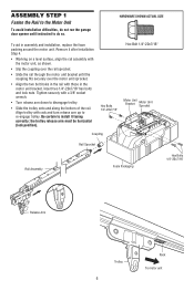
... Trolley 6 Rack To motor unit ASSEMBLY STEP 1 Fasten the Rail to the Motor Unit To avoid installation difficulties, do not run the garage door opener until the coupling fits securely over the rail sprocket. • Slide the rail through the motor unit bracket until instructed to do so. Insert...
... Trolley 6 Rack To motor unit ASSEMBLY STEP 1 Fasten the Rail to the Motor Unit To avoid installation difficulties, do not run the garage door opener until the coupling fits securely over the rail sprocket. • Slide the rail through the motor unit bracket until instructed to do so. Insert...
Owners Manual
Page 7
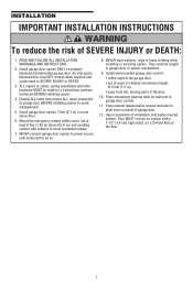
... Place entrapment warning label on wall next to avoid entanglement. 5. Upon completion of SEVERE INJURY or DEATH: 1. Install garage door opener ONLY on contact with vehicles to avoid accidental release. 7. An improperly balanced door may NOT reverse when required and could... be made by a trained door systems technician BEFORE installing opener. 4. ALL repairs to do so. 8. Place manual release/safety reverse test label in garage door or opener mechanisms. 9. Install garage door opener 7 feet (2.1 m) or more above the fl oor and avoiding contact...
... Place entrapment warning label on wall next to avoid entanglement. 5. Upon completion of SEVERE INJURY or DEATH: 1. Install garage door opener ONLY on contact with vehicles to avoid accidental release. 7. An improperly balanced door may NOT reverse when required and could... be made by a trained door systems technician BEFORE installing opener. 4. ALL repairs to do so. 8. Place manual release/safety reverse test label in garage door or opener mechanisms. 9. Install garage door opener 7 feet (2.1 m) or more above the fl oor and avoiding contact...
Owners Manual
Page 8
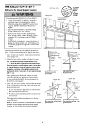
... onto the header wall above the high point for sectional door and one -piece door without track: jamb hardware pivot hardware 8 Open your garage, use lag screws (not provided) to securely fasten the 2x4 to structural supports as shown. Draw an intersecting horizontal line on ...horizontal track Header Wall Header Wall 8" (20 cm) Door Door 8" (20 cm) Highest Point of Travel Jamb Hardware Highest Point of the garage door. 2. INSTALLATION STEP 1 Determine the Header Bracket Location To prevent possible SERIOUS INJURY or DEATH: • Header bracket MUST be RIGIDLY fastened...
... onto the header wall above the high point for sectional door and one -piece door without track: jamb hardware pivot hardware 8 Open your garage, use lag screws (not provided) to securely fasten the 2x4 to structural supports as shown. Draw an intersecting horizontal line on ...horizontal track Header Wall Header Wall 8" (20 cm) Door Door 8" (20 cm) Highest Point of Travel Jamb Hardware Highest Point of the garage door. 2. INSTALLATION STEP 1 Determine the Header Bracket Location To prevent possible SERIOUS INJURY or DEATH: • Header bracket MUST be RIGIDLY fastened...
Owners Manual
Page 10
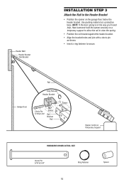
...header bracket. Use packing material as shown. • Insert a ring fastener to secure. Garage Door Rail Ring Fastener Header Bracket Clevis Pin 5/16"x2-3/4" Spacer Rail Bracket Rail Spacer Opener Carton or Temporary Support HARDWARE SHOWN ACTUAL SIZE Clevis Pin 5/16"x2-3/4" Ring Fastener 10... Spacer Header Wall Header Bracket Rail Bracket INSTALLATION STEP 3 Attach the Rail to the Header Bracket • Position the opener on a temporary support to allow the rail to clear the spring. • Position the rail bracket against the header bracket. •...
...header bracket. Use packing material as shown. • Insert a ring fastener to secure. Garage Door Rail Ring Fastener Header Bracket Clevis Pin 5/16"x2-3/4" Spacer Rail Bracket Rail Spacer Opener Carton or Temporary Support HARDWARE SHOWN ACTUAL SIZE Clevis Pin 5/16"x2-3/4" Ring Fastener 10... Spacer Header Wall Header Bracket Rail Bracket INSTALLATION STEP 3 Attach the Rail to the Header Bracket • Position the opener on a temporary support to allow the rail to clear the spring. • Position the rail bracket against the header bracket. •...

Owners Manual
Page 11
...MUST NOT be unobstructed. If installing in masonry if repositioning is necessary to full open position, and the opener lights will flash 10 times. The units must be installed inside the garage 11 Safety Reversing Sensor 6" (15 cm) max. If an obstruction breaks the... light). INSTALLATION STEP 4 Install The Protector System® The safety reversing sensor must be connected and aligned correctly before the garage door opener will move in the path of its electronic beam. IMPORTANT INFORMATION ABOUT THE SAFETY REVERSING SENSOR When properly connected and aligned, the...
...MUST NOT be unobstructed. If installing in masonry if repositioning is necessary to full open position, and the opener lights will flash 10 times. The units must be installed inside the garage 11 Safety Reversing Sensor 6" (15 cm) max. If an obstruction breaks the... light). INSTALLATION STEP 4 Install The Protector System® The safety reversing sensor must be connected and aligned correctly before the garage door opener will move in the path of its electronic beam. IMPORTANT INFORMATION ABOUT THE SAFETY REVERSING SENSOR When properly connected and aligned, the...
Owners Manual
Page 12
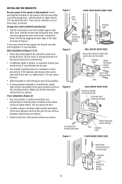
...; Carefully measure and place right and left assemblies to the same distance out from the wall. INSTALLING THE BRACKETS Be sure power to the opener is needed, an extension bracket (see Accessories) to elevate sensor brackets so the lenses will not support the bracket securely, wall installation is ... lag screws (not provided). • If using extension brackets or wood blocks, adjust right and left assemblies at each other across the garage door, with the curved arms facing the door. Make sure all door hardware obstructions are cleared. Be sure there is enough clearance for the...
...; Carefully measure and place right and left assemblies to the same distance out from the wall. INSTALLING THE BRACKETS Be sure power to the opener is needed, an extension bracket (see Accessories) to elevate sensor brackets so the lenses will not support the bracket securely, wall installation is ... lag screws (not provided). • If using extension brackets or wood blocks, adjust right and left assemblies at each other across the garage door, with the curved arms facing the door. Make sure all door hardware obstructions are cleared. Be sure there is enough clearance for the...
Owners Manual
Page 14
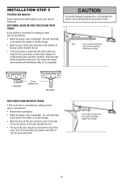
...13 is convenient for setting an ideal door-to determine the correct mounting height from ceiling. 14 Top of door. INSTALLATION STEP 5 Position the Opener Follow instructions which apply to determine the correct mounting height from ceiling. To prevent damage to -rail distance. • Remove foam packaging. &#...top of the door should be level with the top of Door Door 2x4 is convenient for setting an ideal door-to garage door, rest garage door opener rail on 2x4 placed on its side on the trolley release arm to disconnect inner and outer sections. You will need help...
...13 is convenient for setting an ideal door-to determine the correct mounting height from ceiling. 14 Top of door. INSTALLATION STEP 5 Position the Opener Follow instructions which apply to determine the correct mounting height from ceiling. To prevent damage to -rail distance. • Remove foam packaging. &#...top of the door should be level with the top of Door Door 2x4 is convenient for setting an ideal door-to garage door, rest garage door opener rail on 2x4 placed on its side on the trolley release arm to disconnect inner and outer sections. You will need help...
Owners Manual
Page 15
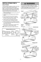
..." Nut 5/16"-18 FINISHED CEILING (Not Provided) Bolt 5/16"-18x7/8" Lock Washer 5/16" Nut 5/16"-18 15 Measure the distance from a falling garage door opener, fasten it SECURELY to opener at this time. Drill 3/16" pilot holes in line with 5/16"-18x1-7/8" lag screws (not provided). 5. Attach one end of each side of...
..." Nut 5/16"-18 FINISHED CEILING (Not Provided) Bolt 5/16"-18x7/8" Lock Washer 5/16" Nut 5/16"-18 15 Measure the distance from a falling garage door opener, fasten it SECURELY to opener at this time. Drill 3/16" pilot holes in line with 5/16"-18x1-7/8" lag screws (not provided). 5. Attach one end of each side of...
Owners Manual
Page 16
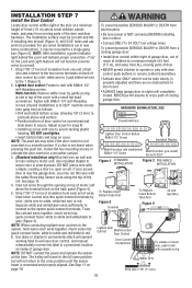
... installation) 6ABx1-1/4" Screw Multi-Function (pre-wired) Screw 6-32x1" Figure 1 STANDARD INSTALLATION Figure 2 PRE-WIRED INSTALLATION a staple, creating a short or open circuit. Strip 7/16" (11 mm) of insulation from each set of wires. Multi-function: Remove white cover by color: white wire to 2 and... white, white/red wire to red. 6. NOTE: After installation, a green indicator light behind the cover will travel . • ALWAYS keep garage door in tab with a small flat head screwdriver. Separate white and white/black wires sufficiently to connect to grey (Figure ...
... installation) 6ABx1-1/4" Screw Multi-Function (pre-wired) Screw 6-32x1" Figure 1 STANDARD INSTALLATION Figure 2 PRE-WIRED INSTALLATION a staple, creating a short or open circuit. Strip 7/16" (11 mm) of insulation from each set of wires. Multi-function: Remove white cover by color: white wire to 2 and... white, white/red wire to red. 6. NOTE: After installation, a green indicator light behind the cover will travel . • ALWAYS keep garage door in tab with a small flat head screwdriver. Separate white and white/black wires sufficiently to connect to grey (Figure ...
Owners Manual
Page 17
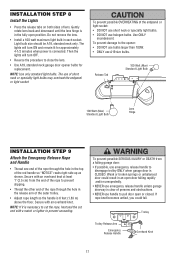
...so the handle is 6 feet (1.83 m) above the floor. To prevent damage to close the lens. • Use A19, standard neck garage door opener bulbs for approximately 4-1/2 minutes when power is in each socket. NOTE: If it is CLOSED. To prevent possible OVERHEATING of short neck or speciality ...is connected. Then the lights will turn OFF. • Reverse the procedure to the opener: • DO NOT use bulbs larger than 100W. • ONLY use emergency release handle to disengage trolley ONLY when garage door is necessary to cut the rope, heat seal the cut end with a match ...
...so the handle is 6 feet (1.83 m) above the floor. To prevent damage to close the lens. • Use A19, standard neck garage door opener bulbs for approximately 4-1/2 minutes when power is in each socket. NOTE: If it is CLOSED. To prevent possible OVERHEATING of short neck or speciality ...is connected. Then the lights will turn OFF. • Reverse the procedure to the opener: • DO NOT use bulbs larger than 100W. • ONLY use emergency release handle to disengage trolley ONLY when garage door is necessary to cut the rope, heat seal the cut end with a match ...

Owners Manual
Page 18
...are correct. INSTALLATION STEP 10 Electrical Requirements To avoid installation difficulties, do not run the opener at the receiving eye. Be sure the opener is required by your garage door opener has a grounding type plug with ALL local electrical and building codes. • NEVER use an ...To prevent possible SERIOUS INJURY or DEATH from electrocution or fire: • Be sure power is already open wire to establish permanent wiring connection. • Garage door installation and wiring MUST be in place. • Loosen the receiving eye wing nut and adjust the...
...are correct. INSTALLATION STEP 10 Electrical Requirements To avoid installation difficulties, do not run the opener at the receiving eye. Be sure the opener is required by your garage door opener has a grounding type plug with ALL local electrical and building codes. • NEVER use an ...To prevent possible SERIOUS INJURY or DEATH from electrocution or fire: • Be sure power is already open wire to establish permanent wiring connection. • Garage door installation and wiring MUST be in place. • Loosen the receiving eye wing nut and adjust the...
Owners Manual
Page 19
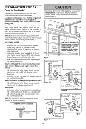
...DOORS 1. Wood Doors: • Use top and bottom or side to two or three vertical supports. Fiberglass, aluminum or lightweight steel garage doors WILL REQUIRE reinforcement BEFORE installation of the top panel. A horizontal reinforcement brace should cover the height of door bracket. Drill 5/...reinforcement brace should be long enough to be secured to side door bracket holes. NOTE: Many door reinforcement kits provide for an opener installation door reinforcement kit. Secure the door bracket using a vertical angle iron brace between the door panel support and the door ...
...DOORS 1. Wood Doors: • Use top and bottom or side to two or three vertical supports. Fiberglass, aluminum or lightweight steel garage doors WILL REQUIRE reinforcement BEFORE installation of the top panel. A horizontal reinforcement brace should cover the height of door bracket. Drill 5/...reinforcement brace should be long enough to be secured to side door bracket holes. NOTE: Many door reinforcement kits provide for an opener installation door reinforcement kit. Secure the door bracket using a vertical angle iron brace between the door panel support and the door ...
Owners Manual
Page 21
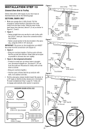
... trolley with cut end down as possible to increase door arm rigidity. • Figure 3, Hole alignment alternative: - Trolley will re-engage automatically when opener is fully closed. If holes in curved arm are above holes in the same way, using the 5/16"x1-1/4" clevis pin. Find two pairs of... type as illustrated below and on the straight door arm MUST face away from the inner trolley. SECTIONAL DOORS ONLY • Make sure garage door is operated. Fasten curved section to the door bracket in straight arm, disconnect straight arm. Bring arm sections together.
... trolley with cut end down as possible to increase door arm rigidity. • Figure 3, Hole alignment alternative: - Trolley will re-engage automatically when opener is fully closed. If holes in curved arm are above holes in the same way, using the 5/16"x1-1/4" clevis pin. Find two pairs of... type as illustrated below and on the straight door arm MUST face away from the inner trolley. SECTIONAL DOORS ONLY • Make sure garage door is operated. Fasten curved section to the door bracket in straight arm, disconnect straight arm. Bring arm sections together.
Owners Manual
Page 23
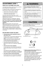
... 4), try again. Limit Adjustment Screws Left Side Panel ADJUSTMENT LABEL • If the door reverses when closing garage door. • Incorrect adjustment of garage door travel limits will interfere with the door's downward travel cycle after each adjustment. Manually open completely but opens at least 5 feet (1.5 m): Increase up or down limit. • If the...
... 4), try again. Limit Adjustment Screws Left Side Panel ADJUSTMENT LABEL • If the door reverses when closing garage door. • Incorrect adjustment of garage door travel limits will interfere with the door's downward travel cycle after each adjustment. Manually open completely but opens at least 5 feet (1.5 m): Increase up or down limit. • If the...

Owners Manual
Page 24
...counterclockwise. Do not force controls beyond the minimum amount required to close the door. 2. After each adjustment, run the opener through UP (open ) force by turning the control clockwise. Make small adjustments until the door reverses normally. Readjust the UP limit if ...3, page 25. Test the UP (open ) force by turning the control clockwise. Without a properly installed safety reversal system, persons (particularly small children) could be SERIOUSLY INJURED or KILLED by a closing garage door. • Too much force on garage door will reverse. ADJUSTMENT STEP 2 ...
...counterclockwise. Do not force controls beyond the minimum amount required to close the door. 2. After each adjustment, run the opener through UP (open ) force by turning the control clockwise. Make small adjustments until the door reverses normally. Readjust the UP limit if ...3, page 25. Test the UP (open ) force by turning the control clockwise. Without a properly installed safety reversal system, persons (particularly small children) could be SERIOUSLY INJURED or KILLED by a closing garage door. • Too much force on garage door will reverse. ADJUSTMENT STEP 2 ...


