
Owners Manual
Page 5
... is also listed below . Model 3240M Model 3130M Model 3240M (1) Model 3130M (1) Multi-Function Door Control Panel Lighted Door Control Button SECURITY✚® 3-Button Remote Control 2 Conductor Bell Wire SECURITY✚® White & White/Red 1-Button Remote Control CEILING MOUNT ONLY UP Remote Control Visor Clip Header Bracket Rail Curved Door...
... is also listed below . Model 3240M Model 3130M Model 3240M (1) Model 3130M (1) Multi-Function Door Control Panel Lighted Door Control Button SECURITY✚® 3-Button Remote Control 2 Conductor Bell Wire SECURITY✚® White & White/Red 1-Button Remote Control CEILING MOUNT ONLY UP Remote Control Visor Clip Header Bracket Rail Curved Door...
Owners Manual
Page 6
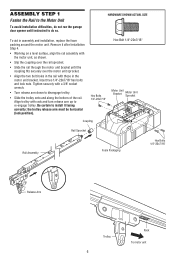
... 1/4"-20x7/16" hex bolts and lock nuts. Be certain to disengage trolley. • Slide the trolley onto and along the bottom of the rail. Tighten securely with a 3/8" socket wrench. • Turn release arm down to install it after Installation Step 4. • Working on a level surface, align the rail ...Fasten the Rail to the Motor Unit To avoid installation difficulties, do not run the garage door opener until the coupling fits securely over the motor unit sprocket. • Align the two bolt holes in the rail with those in assembly and installation, replace the foam packing...
... 1/4"-20x7/16" hex bolts and lock nuts. Be certain to disengage trolley. • Slide the trolley onto and along the bottom of the rail. Tighten securely with a 3/8" socket wrench. • Turn release arm down to install it after Installation Step 4. • Working on a level surface, align the rail ...Fasten the Rail to the Motor Unit To avoid installation difficulties, do not run the garage door opener until the coupling fits securely over the motor unit sprocket. • Align the two bolt holes in the rail with those in assembly and installation, replace the foam packing...
Owners Manual
Page 8
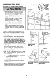
...-piece door without track. You can attach it to the ceiling (see page 9) when clearance is in your garage, use lag screws (not provided) to securely fasten the 2x4 to structural supports as shown. Draw an intersecting horizontal line on the header wall above the high point: • 3" (7.5 cm) above the...
...-piece door without track. You can attach it to the ceiling (see page 9) when clearance is in your garage, use lag screws (not provided) to securely fasten the 2x4 to structural supports as shown. Draw an intersecting horizontal line on the header wall above the high point: • 3" (7.5 cm) above the...
Owners Manual
Page 9
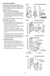
...the hardware provided. If installing into masonry, use the holes designated for positioning only. Drill 3/16" pilot holes and fasten bracket securely to mount the header bracket. Make sure the arrow is for ceiling mount). Finished Ceiling Header Vertical Centerline Bracket of Garage Door... toward the wall. Follow the instructions which will work best for positioning only. Drill 3/16" pilot holes and fasten the bracket securely to mount the header bracket. Vertical Centerline of Garage Door Lag Screws 5/16"-9x1-5/8" Door Spring Lag Screw 5/16"-9x1-5/8" Horizontal...
...the hardware provided. If installing into masonry, use the holes designated for positioning only. Drill 3/16" pilot holes and fasten bracket securely to mount the header bracket. Make sure the arrow is for ceiling mount). Finished Ceiling Header Vertical Centerline Bracket of Garage Door... toward the wall. Follow the instructions which will work best for positioning only. Drill 3/16" pilot holes and fasten the bracket securely to mount the header bracket. Vertical Centerline of Garage Door Lag Screws 5/16"-9x1-5/8" Door Spring Lag Screw 5/16"-9x1-5/8" Horizontal...
Owners Manual
Page 10
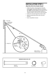
Header Wall Header Bracket Rail Bracket INSTALLATION STEP 3 Attach the Rail to secure. Have someone hold the opener securely on a temporary support to allow the rail to clear the spring. • Position the rail bracket against the header bracket. • Align the bracket holes ...
Header Wall Header Bracket Rail Bracket INSTALLATION STEP 3 Attach the Rail to secure. Have someone hold the opener securely on a temporary support to allow the rail to clear the spring. • Position the rail bracket against the header bracket. • Align the bracket holes ...

Owners Manual
Page 11
... cm) max. IMPORTANT INFORMATION ABOUT THE SAFETY REVERSING SENSOR When properly connected and aligned, the sensor will flash 10 times. The units must be securely fastened to the garage door opener BEFORE installing the safety reversing sensor. The mounting brackets are available if needed. INSTALLATION STEP 4 Install The Protector System...
... cm) max. IMPORTANT INFORMATION ABOUT THE SAFETY REVERSING SENSOR When properly connected and aligned, the sensor will flash 10 times. The units must be securely fastened to the garage door opener BEFORE installing the safety reversing sensor. The mounting brackets are available if needed. INSTALLATION STEP 4 Install The Protector System...
Owners Manual
Page 12
...) above the floor. • Carefully measure and place right and left assemblies to elevate sensor brackets so the lenses will not support the bracket securely, wall installation is disconnected. Make sure all door hardware obstructions are cleared. It should lie flush, with the lip hugging the back edge of...
...) above the floor. • Carefully measure and place right and left assemblies to elevate sensor brackets so the lenses will not support the bracket securely, wall installation is disconnected. Make sure all door hardware obstructions are cleared. It should lie flush, with the lip hugging the back edge of...
Owners Manual
Page 15
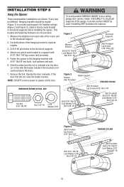
... finished ceilings (Figure 2 and Figure 3), attach a sturdy metal bracket to opener at this time. Measure the distance from a falling garage door opener, fasten it SECURELY to structural supports of the motor unit to a support with 5/16"-18x1-7/8" lag screws (not provided). 5. Drill 3/16" pilot holes in line with 5/16"-18x7...
... finished ceilings (Figure 2 and Figure 3), attach a sturdy metal bracket to opener at this time. Measure the distance from a falling garage door opener, fasten it SECURELY to structural supports of the motor unit to a support with 5/16"-18x1-7/8" lag screws (not provided). 5. Drill 3/16" pilot holes in line with 5/16"-18x7...
Owners Manual
Page 16
...loosen the two mounting screws or relocate the door control to a smoother surface. 3. (Standard installation only) Run bell wire up wall and across ceiling to secure. screws (drywall installation) or 6-32x1" machine screws (into gang box) as in several places. Adjust screw for snug fit. • Install top screw... two screw terminals on inside of garage door. Strip 7/16" (11 mm) of insulation from one end of bell wire and connect to secure wire in new home construction), it can be seen clearly, is properly adjusted and there are no obstructions to door travel to a single gang...
...loosen the two mounting screws or relocate the door control to a smoother surface. 3. (Standard installation only) Run bell wire up wall and across ceiling to secure. screws (drywall installation) or 6-32x1" machine screws (into gang box) as in several places. Adjust screw for snug fit. • Install top screw... two screw terminals on inside of garage door. Strip 7/16" (11 mm) of insulation from one end of bell wire and connect to secure wire in new home construction), it can be seen clearly, is properly adjusted and there are no obstructions to door travel to a single gang...
Owners Manual
Page 17
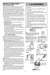
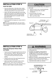
... 4-1/2 minutes when power is clear of the red handle so "NOTICE" reads right side up as shown. To prevent damage to pull door open position. Secure with an overhand knot at least 1" (2.5 cm) from a falling garage door: • If possible, use of lens. INSTALLATION STEP 8 Install the Lights •... and obstructions. • NEVER use handle to the opener: • DO NOT use bulbs larger than 100W. • ONLY use halogen bulbs. Secure with a match or lighter to prevent slipping. • Thread the other end of the rope through the hole in the release arm of the endpanel...
... 4-1/2 minutes when power is clear of the red handle so "NOTICE" reads right side up as shown. To prevent damage to pull door open position. Secure with an overhand knot at least 1" (2.5 cm) from a falling garage door: • If possible, use of lens. INSTALLATION STEP 8 Install the Lights •... and obstructions. • NEVER use handle to the opener: • DO NOT use bulbs larger than 100W. • ONLY use halogen bulbs. Secure with a match or lighter to prevent slipping. • Thread the other end of the rope through the hole in the release arm of the endpanel...
Owners Manual
Page 19
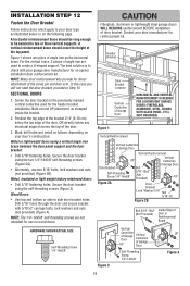
... holes. Position the top edge of the bracket 2"-4" (5-10 cm) below the top edge of angle iron are not intended for reinforcement kit. Secure the door bracket using the two 1/4"-14x5/8" self-threading screws (Figure 2A). • Alternately, use on wood doors. NOTE: The 1/4"-14x5/8"... Metal, insulated or light weight factory reinforced doors: • Drill 3/16" fastening holes. A vertical reinforcement brace should be long enough to be secured to two or three vertical supports. The best solution is to check with 5/16"x2" carriage bolts, lock washers and nuts (not provided) (Figure...
... holes. Position the top edge of the bracket 2"-4" (5-10 cm) below the top edge of angle iron are not intended for reinforcement kit. Secure the door bracket using the two 1/4"-14x5/8" self-threading screws (Figure 2A). • Alternately, use on wood doors. NOTE: The 1/4"-14x5/8"... Metal, insulated or light weight factory reinforced doors: • Drill 3/16" fastening holes. A vertical reinforcement brace should be long enough to be secured to two or three vertical supports. The best solution is to check with 5/16"x2" carriage bolts, lock washers and nuts (not provided) (Figure...
Owners Manual
Page 21
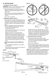
... 1, page 23. IMPORTANT: The groove on the following page. Find two pairs of holes that line up and join with the 5/16"x1" clevis pin. Secure the connection with cut end down as possible to disconnect the outer trolley from the solid end. Reconnect to trolley with a ring fastener. - Pull the...
... 1, page 23. IMPORTANT: The groove on the following page. Find two pairs of holes that line up and join with the 5/16"x1" clevis pin. Secure the connection with cut end down as possible to disconnect the outer trolley from the solid end. Reconnect to trolley with a ring fastener. - Pull the...
Owners Manual
Page 22
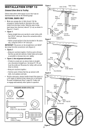
... closed position. If the door has a slight "backward" slant in full open position. - Refer to the door bracket with the 5/16"x1-1/4" clevis pin. • Secure with the remaining clevis pin. Connect the door arm to the trolley: • Close the door and join the curved arm to the floor..., decrease the UP limit until the door is parallel to the connector hole in the illustration. The trolley will travel to make the connection. • Secure with Backward Slant (Incorrect) One full turn equals 2" (5 cm) of the door arm connector hole.
... closed position. If the door has a slight "backward" slant in full open position. - Refer to the door bracket with the 5/16"x1-1/4" clevis pin. • Secure with the remaining clevis pin. Connect the door arm to the trolley: • Close the door and join the curved arm to the floor..., decrease the UP limit until the door is parallel to the connector hole in the illustration. The trolley will travel to make the connection. • Secure with Backward Slant (Incorrect) One full turn equals 2" (5 cm) of the door arm connector hole.
Owners Manual
Page 26
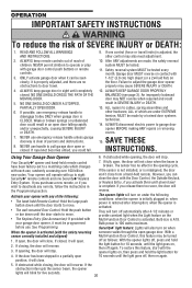
... on , then off again. An improperly balanced door may cause SEVERE INJURY or DEATH. 12. Using Your Garage Door Opener 6. Your Security✚® opener and hand-held remote control have been factory-set to adjust the garage door opener properly may NOT reverse when required and...If the door has been stopped in the Programming section. NO ONE SHOULD GO UNDER A STOPPED, PARTIALLY OPEN DOOR. 6. NEVER use handle to eight Security✚® remote controls and one control (force or travel limits) is adjusted, the other hardware, ALL of the following conditions: when the opener ...
... on , then off again. An improperly balanced door may cause SEVERE INJURY or DEATH. 12. Using Your Garage Door Opener 6. Your Security✚® opener and hand-held remote control have been factory-set to adjust the garage door opener properly may NOT reverse when required and...If the door has been stopped in the Programming section. NO ONE SHOULD GO UNDER A STOPPED, PARTIALLY OPEN DOOR. 6. NEVER use handle to eight Security✚® remote controls and one control (force or travel limits) is adjusted, the other hardware, ALL of the following conditions: when the opener ...
Owners Manual
Page 29
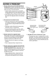
... page. HAVING A PROBLEM? 1. Refer to Installation Step 4: Install The Protector System®. • Check diagnostic LED for the force and limit settings is equipped with a security light feature. Bell Wire Safety Reversing Sensor KG KG "Learn" Button LED or Diagnostic LED Sending Eye Safety Receiving Eye Safety Reversing Sensor Reversing Sensor...
... page. HAVING A PROBLEM? 1. Refer to Installation Step 4: Install The Protector System®. • Check diagnostic LED for the force and limit settings is equipped with a security light feature. Bell Wire Safety Reversing Sensor KG KG "Learn" Button LED or Diagnostic LED Sending Eye Safety Receiving Eye Safety Reversing Sensor Reversing Sensor...
Owners Manual
Page 30
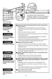
.... Symptom: Sending indicator light glows steadily, receiving indicator light is dim or flashing. • Realign receiving eye sensor, clean lens and secure brackets. • Verify door track is programmed with jumper wire. the motor unit does not operate or trolley is not lit on door control.... Safety reversing sensors wire open (broken or disconnected). Unplug to reset. LED or Diagnostic LED "Learn" Button Your garage door opener is firmly secured to 1-2 ft. (30-60 cm) from motor unit. Symptom: One or both of times then pause signifying it is still flashing 5 ...
.... Symptom: Sending indicator light glows steadily, receiving indicator light is dim or flashing. • Realign receiving eye sensor, clean lens and secure brackets. • Verify door track is programmed with jumper wire. the motor unit does not operate or trolley is not lit on door control.... Safety reversing sensors wire open (broken or disconnected). Unplug to reset. LED or Diagnostic LED "Learn" Button Your garage door opener is firmly secured to 1-2 ft. (30-60 cm) from motor unit. Symptom: One or both of times then pause signifying it is still flashing 5 ...
Owners Manual
Page 31
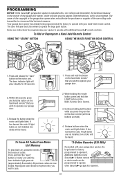
... steadily for programming your garage door. 3. Reprogram each remote or keyless entry you wish to operate your opener to operate with additional Security✚® remote controls. If light bulbs are instructions for 30 seconds. 1. Release the button when the motor unit lights blink....your garage door opener, the large button is operated with your garage door. 2. LOCK LIGHT LOCK LIGHT 4. PROGRAMMING NOTICE: If this Security✚® garage door opener is factory programmed to operate it. Below are not installed, two clicks will be heard. Press and hold...
... steadily for programming your garage door. 3. Reprogram each remote or keyless entry you wish to operate your opener to operate with additional Security✚® remote controls. If light bulbs are instructions for 30 seconds. 1. Release the button when the motor unit lights blink....your garage door opener, the large button is operated with your garage door. 2. LOCK LIGHT LOCK LIGHT 4. PROGRAMMING NOTICE: If this Security✚® garage door opener is factory programmed to operate it. Below are not installed, two clicks will be heard. Press and hold...
Owners Manual
Page 35
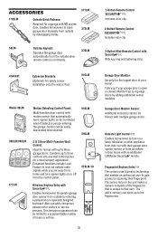
...;® : Enables homeowner to operate garage door opener from the control panel. 379LM-10 Wireless Keyless Entry with an additional LiftMaster Security✚® remote. The unit's memory can be limited to a programmable number of the fingerprint that automatically turns ...Door Monitor Sensor: Additional accessory sensor for homes with NO access door. SEND PASS READY ENROLL ENROLL FAIL RETRY Garage Door Monitor: Security for visitors or service persons. Sensor can store up to turn opener lights on a specially designed keyboard. Combine up to three controls...
...;® : Enables homeowner to operate garage door opener from the control panel. 379LM-10 Wireless Keyless Entry with an additional LiftMaster Security✚® remote. The unit's memory can be limited to a programmable number of the fingerprint that automatically turns ...Door Monitor Sensor: Additional accessory sensor for homes with NO access door. SEND PASS READY ENROLL ENROLL FAIL RETRY Garage Door Monitor: Security for visitors or service persons. Sensor can store up to turn opener lights on a specially designed keyboard. Combine up to three controls...


