Owners Manual
Page 1
® GARAGE DOOR OPENER Models The Chamberlain Group, Inc. 845 Larch Avenue Elmhurst, Illinois 60126-1196 www.liftmaster.com 3130M 1/3 HP For Residential Use Only 3240M 1/2 HP Owner's Manual ■ Please read this manual and the enclosed safety materials carefully! ■ Fasten the manual near the garage door after installation. ■ The door WILL NOT CLOSE unless the Protector System® is connected and properly aligned. ■ Periodic checks of the opener are required to ensure safe operation. ■ The model number label is located on the front panel of your opener.
® GARAGE DOOR OPENER Models The Chamberlain Group, Inc. 845 Larch Avenue Elmhurst, Illinois 60126-1196 www.liftmaster.com 3130M 1/3 HP For Residential Use Only 3240M 1/2 HP Owner's Manual ■ Please read this manual and the enclosed safety materials carefully! ■ Fasten the manual near the garage door after installation. ■ The door WILL NOT CLOSE unless the Protector System® is connected and properly aligned. ■ Periodic checks of the opener are required to ensure safe operation. ■ The model number label is located on the front panel of your opener.
Owners Manual
Page 2
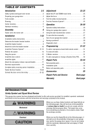
... 8 Install the header bracket 9 Attach the rail to the header bracket 10 Install the Protector System 11-13 Position the opener 14 Hang the opener 15 Install the door control 16 Install the lights 17 Attach the emergency release rope and handle 17 Electrical requirements 18 Complete ...the Protector System 25 Operation 26-30 Operation safety instructions 26 Using your garage door opener 26 Using the wall-mounted door control 27 To open the door manually 27 Care of your garage door opener 28 Having a problem 29 Diagnostic chart 30 Programming 31-32 To add or reprogram...
... 8 Install the header bracket 9 Attach the rail to the header bracket 10 Install the Protector System 11-13 Position the opener 14 Hang the opener 15 Install the door control 16 Install the lights 17 Attach the emergency release rope and handle 17 Electrical requirements 18 Complete ...the Protector System 25 Operation 26-30 Operation safety instructions 26 Using your garage door opener 26 Using the wall-mounted door control 27 To open the door manually 27 Care of your garage door opener 28 Having a problem 29 Diagnostic chart 30 Programming 31-32 To add or reprogram...
Owners Manual
Page 3
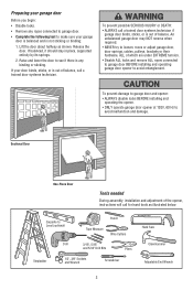
...prevent possible SERIOUS INJURY or DEATH: • ALWAYS call a trained door systems technician if garage door binds, sticks, or is out of the opener, instructions will call a trained door systems technician. Raise and lower the door to see if there is any ropes connected to garage door. ... connected to garage door BEFORE installing and operating garage door opener to avoid entanglement. To prevent damage to garage door and opener: • ALWAYS disable locks BEFORE installing and operating the opener. • ONLY operate garage door opener at 120V, 60 Hz to loosen, move or adjust ...
...prevent possible SERIOUS INJURY or DEATH: • ALWAYS call a trained door systems technician if garage door binds, sticks, or is out of the opener, instructions will call a trained door systems technician. Raise and lower the door to see if there is any ropes connected to garage door. ... connected to garage door BEFORE installing and operating garage door opener to avoid entanglement. To prevent damage to garage door and opener: • ALWAYS disable locks BEFORE installing and operating the opener. • ONLY operate garage door opener at 120V, 60 Hz to loosen, move or adjust ...
Owners Manual
Page 4
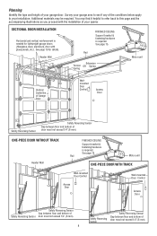
... illustrations as you proceed with glass panels, etc.). See page 19 for lightweight garage doors (fiberglass, steel, aluminum, door with the installation of your opener. SECTIONAL DOOR INSTALLATION Horizontal and vertical reinforcement is required. Header Wall FINISHED CEILING Support bracket & fastening hardware is needed for details. ONE-PIECE DOOR WITHOUT...
... illustrations as you proceed with glass panels, etc.). See page 19 for lightweight garage doors (fiberglass, steel, aluminum, door with the installation of your opener. SECTIONAL DOOR INSTALLATION Horizontal and vertical reinforcement is required. Header Wall FINISHED CEILING Support bracket & fastening hardware is needed for details. ONE-PIECE DOOR WITHOUT...

Owners Manual
Page 5
... 1/4"-20x1/2" (2) Wing Nut 1/4"-20 (2) Rope Handle 5 Accessories will depend on the model purchased. Hardware for installation is also listed below . Carton Inventory Your garage door opener is packaged in the foam.
... 1/4"-20x1/2" (2) Wing Nut 1/4"-20 (2) Rope Handle 5 Accessories will depend on the model purchased. Hardware for installation is also listed below . Carton Inventory Your garage door opener is packaged in the foam.
Owners Manual
Page 6
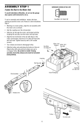
...; Slip the coupling over the rail sprocket. • Slide the rail through the motor unit bracket until instructed to do not run the garage door opener until the coupling fits securely over the motor unit sprocket. • Align the two bolt holes in the rail with those in assembly and...
...; Slip the coupling over the rail sprocket. • Slide the rail through the motor unit bracket until instructed to do not run the garage door opener until the coupling fits securely over the motor unit sprocket. • Align the two bolt holes in the rail with those in assembly and...
Owners Manual
Page 7
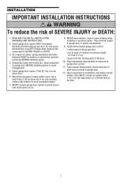
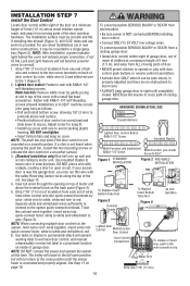
... warning label on properly balanced and lubricated garage door. Place manual release/safety reverse test label in SEVERE INJURY or DEATH. 3. Install garage door opener 7 feet (2.1 m) or more above the fl oor and avoiding contact with a 1-1/2" (3.8 cm) high object (or a 2x4 laid ...flat) on the floor. 7 NEVER wear watches, rings or loose clothing while installing or servicing opener. INSTALLATION IMPORTANT INSTALLATION INSTRUCTIONS WARNING To reduce the risk of installation, test safety reversal system. An improperly balanced door may NOT reverse when...
... warning label on properly balanced and lubricated garage door. Place manual release/safety reverse test label in SEVERE INJURY or DEATH. 3. Install garage door opener 7 feet (2.1 m) or more above the fl oor and avoiding contact with a 1-1/2" (3.8 cm) high object (or a 2x4 laid ...flat) on the floor. 7 NEVER wear watches, rings or loose clothing while installing or servicing opener. INSTALLATION IMPORTANT INSTALLATION INSTRUCTIONS WARNING To reduce the risk of installation, test safety reversal system. An improperly balanced door may NOT reverse when...
Owners Manual
Page 8
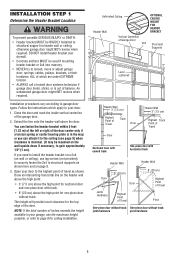
... wall or ceiling), use the maximum height possible, or refer to page 9 for sectional door and one -piece door without track: jamb hardware pivot hardware 8 Open your garage, use lag screws (not provided) to securely fasten the 2x4 to structural supports as shown. Draw an intersecting horizontal line on the header...
... wall or ceiling), use the maximum height possible, or refer to page 9 for sectional door and one -piece door without track: jamb hardware pivot hardware 8 Open your garage, use lag screws (not provided) to securely fasten the 2x4 to structural supports as shown. Draw an intersecting horizontal line on the header...
Owners Manual
Page 10
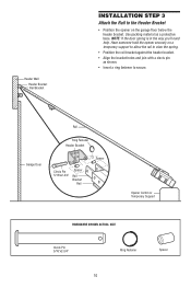
... with a clevis pin as a protective base. Garage Door Rail Ring Fastener Header Bracket Clevis Pin 5/16"x2-3/4" Spacer Rail Bracket Rail Spacer Opener Carton or Temporary Support HARDWARE SHOWN ACTUAL SIZE Clevis Pin 5/16"x2-3/4" Ring Fastener 10 Spacer Use packing material as shown. • Insert ...a ring fastener to the Header Bracket • Position the opener on the garage floor below the header bracket. Header Wall Header Bracket Rail Bracket INSTALLATION STEP 3 Attach the Rail to secure.
... with a clevis pin as a protective base. Garage Door Rail Ring Fastener Header Bracket Clevis Pin 5/16"x2-3/4" Spacer Rail Bracket Rail Spacer Opener Carton or Temporary Support HARDWARE SHOWN ACTUAL SIZE Clevis Pin 5/16"x2-3/4" Ring Fastener 10 Spacer Use packing material as shown. • Insert ...a ring fastener to the Header Bracket • Position the opener on the garage floor below the header bracket. Header Wall Header Bracket Rail Bracket INSTALLATION STEP 3 Attach the Rail to secure.

Owners Manual
Page 11
... Beam 6" (15 cm) max. above garage floor. The invisible light beam path must be connected and aligned correctly before the garage door opener will detect an obstacle in masonry construction, add a piece of wood at each other hardware) may interrupt the beam while the door is necessary.... needed. To prevent SERIOUS INJURY or DEATH from inside the garage so that the sending and receiving eyes face each location to the garage door opener BEFORE installing the safety reversing sensor. If it is NO HIGHER than 6" (15 cm) above floor Facing the door from a closing . If...
... Beam 6" (15 cm) max. above garage floor. The invisible light beam path must be connected and aligned correctly before the garage door opener will detect an obstacle in masonry construction, add a piece of wood at each other hardware) may interrupt the beam while the door is necessary.... needed. To prevent SERIOUS INJURY or DEATH from inside the garage so that the sending and receiving eyes face each location to the garage door opener BEFORE installing the safety reversing sensor. If it is NO HIGHER than 6" (15 cm) above floor Facing the door from a closing . If...
Owners Manual
Page 12
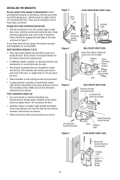
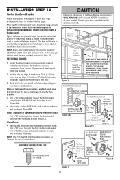
INSTALLING THE BRACKETS Be sure power to the opener is recommended. Be sure all door hardware obstructions are cleared. • Fasten to wall with curved arms facing the door. It should lie flush, ...
INSTALLING THE BRACKETS Be sure power to the opener is recommended. Be sure all door hardware obstructions are cleared. • Fasten to wall with curved arms facing the door. It should lie flush, ...
Owners Manual
Page 14
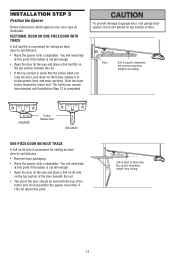
... the correct mounting height from ceiling. 14 You will need help at this point if the ladder is used to garage door, rest garage door opener rail on 2x4 placed on the top section of the door beneath the rail. • The top of the door should be level with the... top of door. Top of Door 2x4 is not tall enough. • Open the door all the way and place a 2x4 laid flat is used to -rail distance. • Remove foam packaging. • Raise the...
... the correct mounting height from ceiling. 14 You will need help at this point if the ladder is used to garage door, rest garage door opener rail on 2x4 placed on the top section of the door beneath the rail. • The top of the door should be level with the... top of door. Top of Door 2x4 is not tall enough. • Open the door all the way and place a 2x4 laid flat is used to -rail distance. • Remove foam packaging. • Raise the...
Owners Manual
Page 15
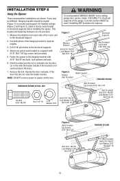
... end of each side of the motor unit to the hanging brackets with 5/16"-18x1-7/8" lag screws (not provided). 5. Fasten the opener to the structural support. 2. Remove the 2x4. Concrete anchors MUST be angled (Figure 1) to make sure the rail is not centered... brackets should be used if installing ANY brackets into masonry. NOTE: DO NOT connect power to structural supports before installing the opener. INSTALLATION STEP 6 Hang the Opener Three representative installations are not provided. 1. Yours may be different. On finished ceilings (Figure 2 and Figure 3), attach...
... end of each side of the motor unit to the hanging brackets with 5/16"-18x1-7/8" lag screws (not provided). 5. Fasten the opener to the structural support. 2. Remove the 2x4. Concrete anchors MUST be angled (Figure 1) to make sure the rail is not centered... brackets should be used if installing ANY brackets into masonry. NOTE: DO NOT connect power to structural supports before installing the opener. INSTALLATION STEP 6 Hang the Opener Three representative installations are not provided. 1. Yours may be different. On finished ceilings (Figure 2 and Figure 3), attach...
Owners Manual
Page 16
... Volt Bell Wire 9 1 7 3 5 KG 9 1 7 3 5 KG NOTE: When connecting multiple door controls to wall with care to the opener quick-connect terminals. Adjust screw for snug fit. • Install top screw with 6ABx1-1/2" self-threading screws. For pre-wired installations (as follows: ... Screw Multi-Function (pre-wired) Screw 6-32x1" Figure 1 STANDARD INSTALLATION Figure 2 PRE-WIRED INSTALLATION a staple, creating a short or open position but will not function (reverse wires to correct). • Be sure power is not heard when pressing the push bar, loosen ...
... Volt Bell Wire 9 1 7 3 5 KG 9 1 7 3 5 KG NOTE: When connecting multiple door controls to wall with care to the opener quick-connect terminals. Adjust screw for snug fit. • Install top screw with 6ABx1-1/2" self-threading screws. For pre-wired installations (as follows: ... Screw Multi-Function (pre-wired) Screw 6-32x1" Figure 1 STANDARD INSTALLATION Figure 2 PRE-WIRED INSTALLATION a staple, creating a short or open position but will not function (reverse wires to correct). • Be sure power is not heard when pressing the push bar, loosen ...
Owners Manual
Page 17
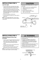
...persons and obstructions. • NEVER use A19 size bulbs. Then the lights will turn OFF. • Reverse the procedure to pull door open position. Trolley Trolley Release Arm Emergency Release Handle NOTICE Overhand Knot 17 Gently rotate lens back and downward until the lens hinge is CLOSED. Secure... socket. To prevent possible SERIOUS INJURY or DEATH from the end of the rope to disengage trolley ONLY when garage door is in an open door falling rapidly and/or unexpectedly. • NEVER use emergency release handle unless garage doorway is clear of the outer trolley. •...
...persons and obstructions. • NEVER use A19 size bulbs. Then the lights will turn OFF. • Reverse the procedure to pull door open position. Trolley Trolley Release Arm Emergency Release Handle NOTICE Overhand Knot 17 Gently rotate lens back and downward until the lens hinge is CLOSED. Secure... socket. To prevent possible SERIOUS INJURY or DEATH from the end of the rope to disengage trolley ONLY when garage door is in an open door falling rapidly and/or unexpectedly. • NEVER use emergency release handle unless garage doorway is clear of the outer trolley. •...

Owners Manual
Page 18
...grounding type outlet. The sending eye amber indicator light will not close. and the ground wire to install the proper outlet. Lock in the opener. TROUBLESHOOTING THE SAFETY REVERSING SENSORS 1. If the sending eye indicator light glows steadily but the receiving eye indicator light doesn't: • Check ...alignment. • Check for : • Electric power to the following procedure. The opener lights will glow steadily if wiring connections and alignment are not installed, 10 clicks can occur at staples, or at this time. Be ...
...grounding type outlet. The sending eye amber indicator light will not close. and the ground wire to install the proper outlet. Lock in the opener. TROUBLESHOOTING THE SAFETY REVERSING SENSORS 1. If the sending eye indicator light glows steadily but the receiving eye indicator light doesn't: • Check ...alignment. • Check for : • Electric power to the following procedure. The opener lights will glow steadily if wiring connections and alignment are not installed, 10 clicks can occur at staples, or at this time. Be ...
Owners Manual
Page 19
... door bracket using the self-threading screws (Figure 3). In this case you will not need the door bracket; Contact your garage door manufacturer for an opener installation door reinforcement kit. A vertical reinforcement brace should be long enough to be secured to two or three vertical supports. Center the door bracket on...
... door bracket using the self-threading screws (Figure 3). In this case you will not need the door bracket; Contact your garage door manufacturer for an opener installation door reinforcement kit. A vertical reinforcement brace should be long enough to be secured to two or three vertical supports. Center the door bracket on...
Owners Manual
Page 21
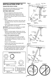
...) from the solid end. IMPORTANT: The groove on the following page. Cut about 2" (5 cm) as shown. - Trolley will re-engage automatically when opener is operated. INSTALLATION STEP 13 Connect Door Arm to Trolley Follow instructions which apply to your door type as possible to increase door arm rigidity... of holes that line up and join sections. Proceed to trolley with bolts, lock washers and nuts. • Pull the emergency release handle toward the opener at a 45° angle so that line up and join with cut end down as shown in Figures 1, 2 and 3. • Figure 1:...
...) from the solid end. IMPORTANT: The groove on the following page. Cut about 2" (5 cm) as shown. - Trolley will re-engage automatically when opener is operated. INSTALLATION STEP 13 Connect Door Arm to Trolley Follow instructions which apply to your door type as possible to increase door arm rigidity... of holes that line up and join sections. Proceed to trolley with bolts, lock washers and nuts. • Pull the emergency release handle toward the opener at a 45° angle so that line up and join with cut end down as shown in Figures 1, 2 and 3. • Figure 1:...
Owners Manual
Page 22
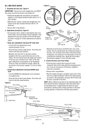
... trolley will travel limit - Refer to the fully closed trolley/door arm positions in the trolley with a ring fastener. • Run the opener through a complete travel cycle. Turn the DOWN limit adjustment screw clockwise 4 complete turns. - Figure 6 Inner Trolley Outer Trolley Door Arm Connector..."-18 5/16" Clevis Pin Straight 5/16"x1-1/4" Arm Bolts 5/16"-18x7/8 Curved Door Arm - Refer to the fully open as illustrated below . • Open door adjustment: decrease UP travel to the connector hole in the illustration. It may be adjusted. Limit adjustment screws are located...
... trolley will travel limit - Refer to the fully closed trolley/door arm positions in the trolley with a ring fastener. • Run the opener through a complete travel cycle. Turn the DOWN limit adjustment screw clockwise 4 complete turns. - Figure 6 Inner Trolley Outer Trolley Door Arm Connector..."-18 5/16" Clevis Pin Straight 5/16"x1-1/4" Arm Bolts 5/16"-18x7/8 Curved Door Arm - Refer to the fully open as illustrated below . • Open door adjustment: decrease UP travel to the connector hole in the illustration. It may be adjusted. Limit adjustment screws are located...
Owners Manual
Page 23
...down travel . One turn equals 2" (5 cm) of 2-4" (5-10 m) between the trolley and the bolt. • If door does not open door provides adequate clearance. If the door is no limit adjustments are outlined below. See Adjustment Step 2. 23 NOTE: To prevent the trolley ...from hitting the cover protection bolt, keep a minimum distance of travel cycle after each adjustment. Run the opener through a complete travel . Use a screwdriver to overheat and shut off. To prevent damage to vehicles, be tested. Turn the down ...
...down travel . One turn equals 2" (5 cm) of 2-4" (5-10 m) between the trolley and the bolt. • If door does not open door provides adequate clearance. If the door is no limit adjustments are outlined below. See Adjustment Step 2. 23 NOTE: To prevent the trolley ...from hitting the cover protection bolt, keep a minimum distance of travel cycle after each adjustment. Run the opener through a complete travel . Use a screwdriver to overheat and shut off. To prevent damage to vehicles, be tested. Turn the down ...


