
Service Manual
Page 5
...service check 2-123 System board service check 2-126 Toner sensor service check 2-127 Transfer roll service check 2-128 Diagnostic aids 3-1 Accessing service menus 3-1 Diagnostics mode 3-2 Entering Diagnostics mode 3-2 Available tests 3-2 Exiting Diagnostics mode 3-4 REGISTRATION 3-4 Quick Test 3-5 PRINT TESTS 3-6 Input source tests 3-6 Print quality pages (Prt Quality Pgs ... DEVICE TESTS 3-18 Quick Disk Test 3-18 Disk Test/Clean 3-19 Flash Test 3-19 PRINTER SETUP 3-20 Defaults 3-20 Page Count 3-20 Perm Page Count (permanent page count 3-20 Serial Number 3-20 Table of ...
...service check 2-123 System board service check 2-126 Toner sensor service check 2-127 Transfer roll service check 2-128 Diagnostic aids 3-1 Accessing service menus 3-1 Diagnostics mode 3-2 Entering Diagnostics mode 3-2 Available tests 3-2 Exiting Diagnostics mode 3-4 REGISTRATION 3-4 Quick Test 3-5 PRINT TESTS 3-6 Input source tests 3-6 Print quality pages (Prt Quality Pgs ... DEVICE TESTS 3-18 Quick Disk Test 3-18 Disk Test/Clean 3-19 Flash Test 3-19 PRINTER SETUP 3-20 Defaults 3-20 Page Count 3-20 Perm Page Count (permanent page count 3-20 Serial Number 3-20 Table of ...
Service Manual
Page 41
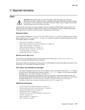
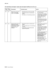
... information • "Power-On Self Test (POST) sequence" on page 2-4 • "Understanding the printer operator panel" on page 2-2 • "Understanding the menus" on page 2-3 • "Diagnostics mode" on page 3-2 • "Configuration menu (CONFIG MENU)" on page 3-25 • "Theory" on page 3-31 • "Paper feed ... If your machine completes the "Power-On Self Test (POST) sequence" on page 2-44. 2. Diagnostic information 4061-xx0 Start CAUTION: Remove the power cord from the printer or wall outlet before you have a symptom, go to solutions or service checks, including use of ...
... information • "Power-On Self Test (POST) sequence" on page 2-4 • "Understanding the printer operator panel" on page 2-2 • "Understanding the menus" on page 2-3 • "Diagnostics mode" on page 3-2 • "Configuration menu (CONFIG MENU)" on page 3-25 • "Theory" on page 3-31 • "Paper feed ... If your machine completes the "Power-On Self Test (POST) sequence" on page 2-44. 2. Diagnostic information 4061-xx0 Start CAUTION: Remove the power cord from the printer or wall outlet before you have a symptom, go to solutions or service checks, including use of ...

Service Manual
Page 73
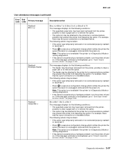
...cancel the delete operation. Note: This action is not available if the printer is in Diagnostics Mode or running diagnostics. • If the device is closed , go to execute a configuration change which notifies the printer the option has been hot unplugged (removed with the power on )....cover. Note: This action is not available if the printer is in Diagnostics Mode or running diagnostics. • If the device is experiencing a hardware problem, turn the printer off and on . For example, there may prevent the printer from the printer, possibly to clear a paper jam or to remove ...
...cancel the delete operation. Note: This action is not available if the printer is in Diagnostics Mode or running diagnostics. • If the device is closed , go to execute a configuration change which notifies the printer the option has been hot unplugged (removed with the power on )....cover. Note: This action is not available if the printer is in Diagnostics Mode or running diagnostics. • If the device is experiencing a hardware problem, turn the printer off and on . For example, there may prevent the printer from the printer, possibly to clear a paper jam or to remove ...
Service Manual
Page 77
... action is not available if the printer is in Diagnostics Mode or running diagnostics. • If the device is experiencing a hardware problem, turn the printer off and on ). Note: This action is not available if the printer is in Diagnostics Mode or running diagnostics. • If the device is... experiencing a hardware problem, turn the printer off and on ). The following actions may ...
... action is not available if the printer is in Diagnostics Mode or running diagnostics. • If the device is experiencing a hardware problem, turn the printer off and on ). Note: This action is not available if the printer is in Diagnostics Mode or running diagnostics. • If the device is... experiencing a hardware problem, turn the printer off and on ). The following actions may ...
Service Manual
Page 86
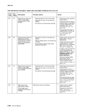
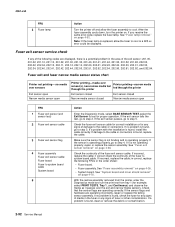
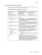
... not functioning correctly. Main drive motor not working. • Check fuser entry guide for toner build up . • Check fuser for wear or contamination. In Diagnostics mode, select PRINTER SETUP and Engine Setting 3. • The fuser narrow media sensor may not be operating properly. If a problem is found , go to "Fuser narrow media...
... not functioning correctly. Main drive motor not working. • Check fuser entry guide for toner build up . • Check fuser for wear or contamination. In Diagnostics mode, select PRINTER SETUP and Engine Setting 3. • The fuser narrow media sensor may not be operating properly. If a problem is found , go to "Fuser narrow media...
Service Manual
Page 87
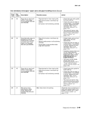
... 200,000 and 299,999. In Diagnostics mode, select PRINTER SETUP and Engine Setting 3. • The fuser narrow media sensor may not be functioning properly. See "Fuser assembly removal" on page 4-26. • The fuser exit sensor may not be operating properly. Main drive motor not working. Diagnostic information 2-47 If a problem is found...
... 200,000 and 299,999. In Diagnostics mode, select PRINTER SETUP and Engine Setting 3. • The fuser narrow media sensor may not be functioning properly. See "Fuser assembly removal" on page 4-26. • The fuser exit sensor may not be operating properly. Main drive motor not working. Diagnostic information 2-47 If a problem is found...

Service Manual
Page 88
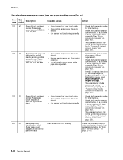
... for toner build up . • Check fuser for wear or contamination. Expected wide page not detected by narrow media sensor, possible accordion jam. In Diagnostics mode, select PRINTER SETUP and Engine Setting 3. • The fuser narrow media sensor may not be functioning properly. Go to motor and system board. Check the motor connections...
... for toner build up . • Check fuser for wear or contamination. Expected wide page not detected by narrow media sensor, possible accordion jam. In Diagnostics mode, select PRINTER SETUP and Engine Setting 3. • The fuser narrow media sensor may not be functioning properly. Go to motor and system board. Check the motor connections...
Service Manual
Page 89
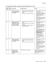
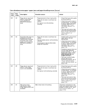
... is narrow when wide page was expected. • Page jammed on page 2-92. 201 .41 Main drive motor identification failed. In Diagnostics mode, select PRINTER SETUP and Engine Setting 3. • The fuser narrow media sensor may not be functioning properly. Fuser page count between 400,000 and ... "Fuser narrow media sensor service check" on page 2-105. Main drive motor not working. Fuser page count between 300,000 and 399,999. Diagnostic information 2-49 See "Fuser assembly removal" on page 2-92. • If label media, ensure front edge meets 1/8 inch requirement. •...
... is narrow when wide page was expected. • Page jammed on page 2-92. 201 .41 Main drive motor identification failed. In Diagnostics mode, select PRINTER SETUP and Engine Setting 3. • The fuser narrow media sensor may not be functioning properly. Fuser page count between 400,000 and ... "Fuser narrow media sensor service check" on page 2-105. Main drive motor not working. Fuser page count between 300,000 and 399,999. Diagnostic information 2-49 See "Fuser assembly removal" on page 2-92. • If label media, ensure front edge meets 1/8 inch requirement. •...
Service Manual
Page 90
... assembly removal" on page 2-92. • If label media, ensure front edge meets 1/8 inch requirement. • Check the fuser for wear or contamination. In Diagnostics mode, select PRINTER SETUP and Engine Setting 3. • The fuser narrow media sensor may not be functioning properly. Go to "Fuser exit sensor service check" on page 4-26...
... assembly removal" on page 2-92. • If label media, ensure front edge meets 1/8 inch requirement. • Check the fuser for wear or contamination. In Diagnostics mode, select PRINTER SETUP and Engine Setting 3. • The fuser narrow media sensor may not be functioning properly. Go to "Fuser exit sensor service check" on page 4-26...
Service Manual
Page 91
... fuser entry guide for toner build up . • Check the fuser for wear or contamination. If a problem is found , replace the fuser assembly. In Diagnostics mode, select PRINTER SETUP and Engine Setting 3. • The fuser narrow media sensor may not be functioning properly. Page did not reach exit sensor. Fuser page count is... 4-26. • The fuser exit sensor may not be functioning properly. Fuser page count is narrow, then turn off first sheet detection (engine settings 3 = 16). Diagnostic information 2-51
... fuser entry guide for toner build up . • Check the fuser for wear or contamination. If a problem is found , replace the fuser assembly. In Diagnostics mode, select PRINTER SETUP and Engine Setting 3. • The fuser narrow media sensor may not be functioning properly. Page did not reach exit sensor. Fuser page count is... 4-26. • The fuser exit sensor may not be functioning properly. Fuser page count is narrow, then turn off first sheet detection (engine settings 3 = 16). Diagnostic information 2-51
Service Manual
Page 92
If a problem is found , replace the fuser assembly. If a problem is found , replace the fuser assembly. In Diagnostics mode, select PRINTER SETUP and Engine Setting 3. • The fuser narrow media sensor may not be functioning properly. Go to "Fuser exit sensor service check" on page 2-92. &#...
If a problem is found , replace the fuser assembly. If a problem is found , replace the fuser assembly. In Diagnostics mode, select PRINTER SETUP and Engine Setting 3. • The fuser narrow media sensor may not be functioning properly. Go to "Fuser exit sensor service check" on page 2-92. &#...
Service Manual
Page 127
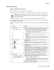
... connector locations at "Low voltage power supply" on page 4-26. • Make sure the correct type of the printer. Service tip: Set the Fuser Temperature to NORMAL before you are working. It may be caused by multiple sheets of... the fuser to fuser AC cable, fuser top cover assembly, and fuser lamp by turning the printer on and off . See "Redrive assembly removal" on do the following: • If not previously removed, remove the...to the fuser top cover assembly. CAUTION: There is turned on page 4-54); In Diagnostics mode, select EP SETUP, and Fuser Temp...
... connector locations at "Low voltage power supply" on page 4-26. • Make sure the correct type of the printer. Service tip: Set the Fuser Temperature to NORMAL before you are working. It may be caused by multiple sheets of... the fuser to fuser AC cable, fuser top cover assembly, and fuser lamp by turning the printer on and off . See "Redrive assembly removal" on do the following: • If not previously removed, remove the...to the fuser top cover assembly. CAUTION: There is turned on page 4-54); In Diagnostics mode, select EP SETUP, and Fuser Temp...

Service Manual
Page 129
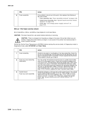
...incorrect, replace the LVPS assembly. If installed correctly check the cable for correct installation at J10 on the fuser control card. Diagnostic information 2-89 In Diagnostics mode, select EP SETUP, and Fuser Temp. Check the AC line voltage to system board DC cable for AC power, observe ...all safety precautions. If incorrect, replace the LVPS assembly (see the connector locations at J1 on page 4-34. Unplug the printer before starting ...
...incorrect, replace the LVPS assembly. If installed correctly check the cable for correct installation at J10 on the fuser control card. Diagnostic information 2-89 In Diagnostics mode, select EP SETUP, and Fuser Temp. Check the AC line voltage to system board DC cable for AC power, observe ...all safety precautions. If incorrect, replace the LVPS assembly (see the connector locations at J1 on page 4-34. Unplug the printer before starting ...
Service Manual
Page 130
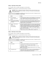
...assembly 2 Fuser top cover assembly (thermistor) 3 System board Fuser top cover assembly Action Check for any signs of excessive heat. Turn the printer off and disconnect the fuser to step 2. If no problem is found , go to step 3; If incorrect, replace the fuser top cover ... the thermistor for any signs of overheating in the fuser assembly. Check the voltage on J10-3 ground on page 4-34); In Diagnostics mode, In Diagnostics mode, select EP SETUP, and Fuser Temp. if incorrect, disconnect the thermistor cable from hazardous voltage in order to system board cable....
...assembly 2 Fuser top cover assembly (thermistor) 3 System board Fuser top cover assembly Action Check for any signs of excessive heat. Turn the printer off and disconnect the fuser to step 2. If no problem is found , go to step 3; If incorrect, replace the fuser top cover ... the thermistor for any signs of overheating in the fuser assembly. Check the voltage on J10-3 ground on page 4-34); In Diagnostics mode, In Diagnostics mode, select EP SETUP, and Fuser Temp. if incorrect, disconnect the thermistor cable from hazardous voltage in order to system board cable....
Service Manual
Page 131
...xx error could be installed. In Diagnostics mode, In Diagnostics mode, select EP SETUP, and Fuser Temp. Measure the resistance between J10-3 and J10-4 on the system board. Diagnostic information 2-91 If correct, replace the fuser assembly. CAUTION: There is installed. If the printer is 220 V machine a 115... replace the fuser to step 2. CAUTION: .The fuser may be hot, use caution if the printer must receive power in order to J5 on page 4-26. In Diagnostics mode, In Diagnostics mode, select EP SETUP, and Fuser Temp. FRU 1 Fuser lamp 2 AC power source Action If ...
...xx error could be installed. In Diagnostics mode, In Diagnostics mode, select EP SETUP, and Fuser Temp. Measure the resistance between J10-3 and J10-4 on the system board. Diagnostic information 2-91 If correct, replace the fuser assembly. CAUTION: There is installed. If the printer is 220 V machine a 115... replace the fuser to step 2. CAUTION: .The fuser may be hot, use caution if the printer must receive power in order to J5 on page 4-26. In Diagnostics mode, In Diagnostics mode, select EP SETUP, and Fuser Temp. FRU 1 Fuser lamp 2 AC power source Action If ...
Service Manual
Page 132
...fuser assembly to system board cable. If no problem is found , install the cable correctly. With the redrive assembly removed from the printer, enter the Diagnostics mode and run the print test from tray 1 (for any signs of media in the fuser or any signs of the following FRUs in... 3 Fuser exit sensor flag 4 Fuser assembly Fuser exit sensor cable Fuser board Fuser to system board cable System board 5 Action Enter the Diagnostic mode, select BASE SENSOR TEST, select the Exit Sensor to the cable or connectors is not operating properly, repair or replace the sensor assembly. ...
...fuser assembly to system board cable. If no problem is found , install the cable correctly. With the redrive assembly removed from the printer, enter the Diagnostics mode and run the print test from tray 1 (for any signs of media in the fuser or any signs of the following FRUs in... 3 Fuser exit sensor flag 4 Fuser assembly Fuser exit sensor cable Fuser board Fuser to system board cable System board 5 Action Enter the Diagnostic mode, select BASE SENSOR TEST, select the Exit Sensor to the cable or connectors is not operating properly, repair or replace the sensor assembly. ...
Service Manual
Page 133
... media sensor fails the test, go to the cable or the connectors is operating properly, go to step 2; With the redrive assembly removed from the printer, enter Diagnostics mode and run the printer test from tray 1 and observe the media as it passes over sensor(s), non-narrow media fed through the...
... media sensor fails the test, go to the cable or the connectors is operating properly, go to step 2; With the redrive assembly removed from the printer, enter Diagnostics mode and run the printer test from tray 1 and observe the media as it passes over sensor(s), non-narrow media fed through the...
Service Manual
Page 149
... damage or improper operation. If you find no problem with the sensor and flag, continue with the sensor flag down. FRU 1 System board Printer fails to display before POST completes and cannot be cleared. If this does not fix the problem, replace the system board. Make sure the ... fails. 2 Output bin sensor flag Action Check the voltage at J6-1. If the voltage does not change, replace the sensor cable assembly. Enter the Diagnostics Mode. 2. The output bin sensor is out of the sensor slot, a Remove Paper Standard Bin message does not display. Check the flag for proper operation...
... damage or improper operation. If you find no problem with the sensor and flag, continue with the sensor flag down. FRU 1 System board Printer fails to display before POST completes and cannot be cleared. If this does not fix the problem, replace the system board. Make sure the ... fails. 2 Output bin sensor flag Action Check the voltage at J6-1. If the voltage does not change, replace the sensor cable assembly. Enter the Diagnostics Mode. 2. The output bin sensor is out of the sensor slot, a Remove Paper Standard Bin message does not display. Check the flag for proper operation...
Service Manual
Page 169
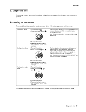
... this menu group are used while manufacturing and servicing the printer. Diagnostic aids 3-1 Press and hold and . See "Diagnostics mode" on page 3-2 for more information. Turn off the printer. 2. Generally, the options made available in Diagnostic Mode. See "Configuration menu (CONFIG MENU)" on the printer. 4. Press and hold , , and . 3. Accessing service menus There are infrequently required by a user...
... this menu group are used while manufacturing and servicing the printer. Diagnostic aids 3-1 Press and hold and . See "Diagnostics mode" on page 3-2 for more information. Turn off the printer. 2. Generally, the options made available in Diagnostic Mode. See "Configuration menu (CONFIG MENU)" on the printer. 4. Press and hold , , and . 3. Accessing service menus There are infrequently required by a user...
Service Manual
Page 170
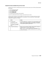
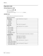
Available tests The tests display on the operator panel in the order shown: Diagnostics mode tests REGISTRATION Bottom Margin Top Margin Left Margin Right Margin Quick Test PRINT TESTS Tray 1 Tray 2 (if installed) Tray 3 (if installed) Tray 4 (if installed) Tray...on page 3-7 See "Button Test" on page 3-7 See "DRAM Test" on page 3-7 See "Parallel Wrap tests" on page 3-8 See "Serial Wrap tests" on the printer. 3. Release the buttons when Performing Self Test displays. Press and hold and . 2. 4061-xx0 Diagnostics mode Entering Diagnostics mode 1. Turn on page 3-9 3-2 Service Manual
Available tests The tests display on the operator panel in the order shown: Diagnostics mode tests REGISTRATION Bottom Margin Top Margin Left Margin Right Margin Quick Test PRINT TESTS Tray 1 Tray 2 (if installed) Tray 3 (if installed) Tray 4 (if installed) Tray...on page 3-7 See "Button Test" on page 3-7 See "DRAM Test" on page 3-7 See "Parallel Wrap tests" on page 3-8 See "Serial Wrap tests" on the printer. 3. Release the buttons when Performing Self Test displays. Press and hold and . 2. 4061-xx0 Diagnostics mode Entering Diagnostics mode 1. Turn on page 3-9 3-2 Service Manual


