
User's Guide
Page 138
... Warning: Electrical surges can be multiplied by power surges. If you must attach a suitably rated and certified power-regulating device (such as a voltage stabilizer or UPS device) to the printer power supply. Maximum Voltage Nominal Voltage Range Range 100V-110V AC 90V-117V AC 110V-127V ... for C520 and C522 17 W for C524 16 W for C522 18 W for C524 network models and C524 duplex network model The power consumption levels listed in the previous table represent time-averaged measurements. Since power consumption claims are provided in power units of Watts, the power consumption should be...
... Warning: Electrical surges can be multiplied by power surges. If you must attach a suitably rated and certified power-regulating device (such as a voltage stabilizer or UPS device) to the printer power supply. Maximum Voltage Nominal Voltage Range Range 100V-110V AC 90V-117V AC 110V-127V ... for C520 and C522 17 W for C524 16 W for C522 18 W for C524 network models and C524 duplex network model The power consumption levels listed in the previous table represent time-averaged measurements. Since power consumption claims are provided in power units of Watts, the power consumption should be...
Service Manual
Page 15
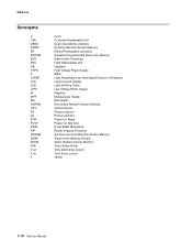
... Light Amplification by Stimulated Emission of Radiation Liquid Crystal Display Light-Emitting Diode Low Voltage Power Supply Magenta Multipurpose Feeder Microswitch Nonvolatile Random Access Memory Optical Sensor Photoconductor Picture element Power-On Reset Power-On Self Test Pulse Width Modulation Raster Imaging Processor Synchronous Dual Random Access Memory Single Inline Memory Module Static Random...
... Light Amplification by Stimulated Emission of Radiation Liquid Crystal Display Light-Emitting Diode Low Voltage Power Supply Magenta Multipurpose Feeder Microswitch Nonvolatile Random Access Memory Optical Sensor Photoconductor Picture element Power-On Reset Power-On Self Test Pulse Width Modulation Raster Imaging Processor Synchronous Dual Random Access Memory Single Inline Memory Module Static Random...

Service Manual
Page 40
...; Remove the top access cover assembly (see "Top access cover assembly removal- Disconnect and reconnect the cable to snap it into the groove. High voltage power supply High voltage contact path Finger • If the contacts are missing. Diagnostic information 2-25 You need to press down the operator panel to ease the... the system card and the HVPS. See "System card removal" on page 4-62. • If the problem persists, replace the system card. See "High voltage power supply (HVPS) removal" on page 4-79.
...; Remove the top access cover assembly (see "Top access cover assembly removal- Disconnect and reconnect the cable to snap it into the groove. High voltage power supply High voltage contact path Finger • If the contacts are missing. Diagnostic information 2-25 You need to press down the operator panel to ease the... the system card and the HVPS. See "System card removal" on page 4-62. • If the problem persists, replace the system card. See "High voltage power supply (HVPS) removal" on page 4-79.
Service Manual
Page 43
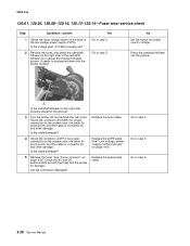
...to step 4. Is the voltage level (115/230) properly set? 2 Remove the fuser, and check the camshaft follower on the back of the low voltage power supply (LVPS). Is the cable damaged? 4 Check the connector JLVPS1 for any other damage. Go to step 3. 5022-xxx 120.01, 120.02, 120.08...-Fuser error service check Step Questions / actions 1 Check the input voltage switch on the right side. No Set the switch for damage. See "Low voltage power supply (LVPS) removal" on the right side properly placed in the groove? 3 Turn the printer off, and remove the rear cover. Go to step 5. A Is...
...to step 4. Is the voltage level (115/230) properly set? 2 Remove the fuser, and check the camshaft follower on the back of the low voltage power supply (LVPS). Is the cable damaged? 4 Check the connector JLVPS1 for any other damage. Go to step 3. 5022-xxx 120.01, 120.02, 120.08...-Fuser error service check Step Questions / actions 1 Check the input voltage switch on the right side. No Set the switch for damage. See "Low voltage power supply (LVPS) removal" on the right side properly placed in the groove? 3 Turn the printer off, and remove the rear cover. Go to step 5. A Is...

Service Manual
Page 45
...the cable or connector for proper connection to step 3. Replace the LVPS. Check the AC and DC autoconnects on the back of the low voltage power supply (LVPS). 5022-xxx 120.03-Fuser error service check Step Questions / actions Yes 1 Check the input voltage switch on page 4-65. 4... Replace the fuser. See "Low voltage power supply (LVPS) removal" on the back of the low voltage power supply (LVPS). Replace the appropriate cable. 2-30 Service Manual Go to the system card, the cable for pinch points, and...
...the cable or connector for proper connection to step 3. Replace the LVPS. Check the AC and DC autoconnects on the back of the low voltage power supply (LVPS). 5022-xxx 120.03-Fuser error service check Step Questions / actions Yes 1 Check the input voltage switch on page 4-65. 4... Replace the fuser. See "Low voltage power supply (LVPS) removal" on the back of the low voltage power supply (LVPS). Replace the appropriate cable. 2-30 Service Manual Go to the system card, the cable for pinch points, and...

Service Manual
Page 57
... solved. Turn the printer on page 4-83. See "Toner level sensor removal" on . No Go to the system card and the HVPS. See "High voltage power supply (HVPS) removal" on any of the pins? 5 Replace the HVPS. Does the error clear? You will need to the ground, and check the voltage on...
... solved. Turn the printer on page 4-83. See "Toner level sensor removal" on . No Go to the system card and the HVPS. See "High voltage power supply (HVPS) removal" on any of the pins? 5 Replace the HVPS. Does the error clear? You will need to the ground, and check the voltage on...

Service Manual
Page 64
... magenta1 and magenta2, or black1 and black2) on page 4-79. See "System card removal" on the transfer contact assembly. See "High voltage power supply (HVPS) removal" on page 4-62. Go to step 4. 5022-xxx No Replace the transfer contact assembly. Diagnostic information 2-49 Step Questions /... actions Yes 3 Remove the HVPS. supply (HVPS) removal" on page 4-62. Replace the system card. See "Transfer contact assembly removal" on page 4-92. yellow2 cyan2 magenta2 black2 ...
... magenta1 and magenta2, or black1 and black2) on page 4-79. See "System card removal" on the transfer contact assembly. See "High voltage power supply (HVPS) removal" on page 4-62. Go to step 4. 5022-xxx No Replace the transfer contact assembly. Diagnostic information 2-49 Step Questions /... actions Yes 3 Remove the HVPS. supply (HVPS) removal" on page 4-62. Replace the system card. See "Transfer contact assembly removal" on page 4-92. yellow2 cyan2 magenta2 black2 ...
Service Manual
Page 66
... from hazardous voltage in the area of the product where you begin, or use caution if the product must receive power in order to step 4. Go to step 6. See "Low voltage power supply (LVPS) removal" on page 4-79. Go to step 2. No Replace the system card with a new, and not previously installed smart...
... from hazardous voltage in the area of the product where you begin, or use caution if the product must receive power in order to step 4. Go to step 6. See "Low voltage power supply (LVPS) removal" on page 4-79. Go to step 2. No Replace the system card with a new, and not previously installed smart...

Service Manual
Page 71
Transfer belt high voltage path (typical 4X) Replace the spring or the transfer contact assembly. Go to step 5. See "High voltage power supply (HVPS) removal" on page 3-8. Does this fix the problem? 3 Yes Go to step 2. Problem solved. See "General motor tests" on page 4-62. Replace the EP ...
Transfer belt high voltage path (typical 4X) Replace the spring or the transfer contact assembly. Go to step 5. See "High voltage power supply (HVPS) removal" on page 3-8. Does this fix the problem? 3 Yes Go to step 2. Problem solved. See "General motor tests" on page 4-62. Replace the EP ...

Service Manual
Page 72
... the left printer frame. See "Transfer contact assembly removal" on page 4-62. Go to the photoconductor charge roll. See "High voltage power supply (HVPS) removal" on page 4-92 to view the proper mounting and for removal procedures. to step 7. Problem solved. Go to step... 6. Pin 1 7 Replace the HVPS. Diagnostic information 2-57 High voltage power supply High voltage contact path Are the spring(s) defective? 6 Turn off the printer and check the continuity of the HVPS cable. Pin 1...
... the left printer frame. See "Transfer contact assembly removal" on page 4-62. Go to the photoconductor charge roll. See "High voltage power supply (HVPS) removal" on page 4-92 to view the proper mounting and for removal procedures. to step 7. Problem solved. Go to step... 6. Pin 1 7 Replace the HVPS. Diagnostic information 2-57 High voltage power supply High voltage contact path Are the spring(s) defective? 6 Turn off the printer and check the continuity of the HVPS cable. Pin 1...

Service Manual
Page 73
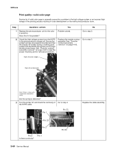
... between bands either 27 or 36mm? Yes Replace the print cartridge. Print quality-horizontal line The photoconductor unit is not properly seated. see "Low voltage power supply (LVPS) removal" on page 4-70. Print quality-mottle (2-5mm speckles) Keep running prints through, and the problem normally clears up. Print quality-half-color page...
... between bands either 27 or 36mm? Yes Replace the print cartridge. Print quality-horizontal line The photoconductor unit is not properly seated. see "Low voltage power supply (LVPS) removal" on page 4-70. Print quality-mottle (2-5mm speckles) Keep running prints through, and the problem normally clears up. Print quality-half-color page...
Service Manual
Page 75
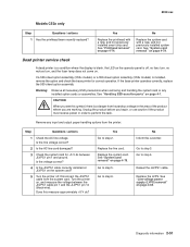
... "Transfer contact assembly removal" on page 4-92 to the photoconductor charge roll. Go to step 4. Does this fix the problem? Go to step 3. High volt power supply High volt contact path Note: Printer is shown with the HPVS spring that runs through the left printer frame. Replace the transfer contact assembly. Go...
... "Transfer contact assembly removal" on page 4-92 to the photoconductor charge roll. Go to step 4. Does this fix the problem? Go to step 3. High volt power supply High volt contact path Note: Printer is shown with the HPVS spring that runs through the left printer frame. Replace the transfer contact assembly. Go...

Service Manual
Page 76
Diagnostic information 2-61 Step Questions / actions Yes 4 Replace the HVPS. Problem solved. See "High voltage power supply (HVPS) removal" on page 4-79. See "System card removal" on page 4-62. Did this solve the problem? Print quality-vertical banding Replace the developer cartridge. 5022-xxx No Replace the system card.
Diagnostic information 2-61 Step Questions / actions Yes 4 Replace the HVPS. Problem solved. See "High voltage power supply (HVPS) removal" on page 4-79. See "System card removal" on page 4-62. Did this solve the problem? Print quality-vertical banding Replace the developer cartridge. 5022-xxx No Replace the system card.

Service Manual
Page 121
During the print process, an image is the brain of the system card converts the data into a raster image and feeds this data along with control information to the system card. 5022-xxx Electrophotographic (EP) process Main components High voltage power supply Fuser Printhead Developer (toner) cartridge Transfer belt Photoconductor belt System card The system card is sent from a computer to the printhead. 3-44 Service Manual The raster image processor (RIP) portion of the printer.
During the print process, an image is the brain of the system card converts the data into a raster image and feeds this data along with control information to the system card. 5022-xxx Electrophotographic (EP) process Main components High voltage power supply Fuser Printhead Developer (toner) cartridge Transfer belt Photoconductor belt System card The system card is sent from a computer to the printhead. 3-44 Service Manual The raster image processor (RIP) portion of the printer.
Service Manual
Page 122
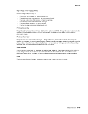
...). The toner adheres to the print media. Toner cartridge This unit consists primarily of the photoconductor drum which is to supply charge toner to by the laser. 5022-xxx High voltage power supply (HVPS) Provides a high voltage charge to fuse the toner image onto the print media. Once the photoconductor drum has been...
...). The toner adheres to the print media. Toner cartridge This unit consists primarily of the photoconductor drum which is to supply charge toner to by the laser. 5022-xxx High voltage power supply (HVPS) Provides a high voltage charge to fuse the toner image onto the print media. Once the photoconductor drum has been...
Service Manual
Page 123
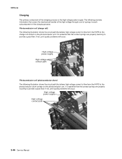
... charge roll contact on the photoconductor unit. It is the high voltage power supply. If not, print quality problems will occur. If not, print quality problems will occur. High voltage power supply High voltage contact path Photoconductor unit (photoconductor drum) The following illustration shows...subcomponent of the charging process is essential that the contact springs are properly touching to provide a good flow. High voltage power supply High voltage contact path 3-46 Service Manual The following illustration shows the circuit path that allows high voltage current to ...
... charge roll contact on the photoconductor unit. It is the high voltage power supply. If not, print quality problems will occur. If not, print quality problems will occur. High voltage power supply High voltage contact path Photoconductor unit (photoconductor drum) The following illustration shows...subcomponent of the charging process is essential that the contact springs are properly touching to provide a good flow. High voltage power supply High voltage contact path 3-46 Service Manual The following illustration shows the circuit path that allows high voltage current to ...

Service Manual
Page 124
... the circuit path that allows high voltage current to flow from the HVPS. These three parts are properly touching to the toner cartridge. High voltage power supply Cleaner blade high voltage contact path Toner add roll high voltage contact path Developer roll high voltage contact path Diagnostic aids 3-47 It is essential...
... the circuit path that allows high voltage current to flow from the HVPS. These three parts are properly touching to the toner cartridge. High voltage power supply Cleaner blade high voltage contact path Toner add roll high voltage contact path Developer roll high voltage contact path Diagnostic aids 3-47 It is essential...

Service Manual
Page 132
... 24 V switch opens, the normally open side of the top cover camshaft assembly. When the top door is mounted to disable a +24 V power supply output, turning off all high voltage supplies, the bump/align motor, the duplex motor and the fuser motor for safety considerations. Diagnostic aids 3-55 5022-xxx 24 V interlock switch...
... 24 V switch opens, the normally open side of the top cover camshaft assembly. When the top door is mounted to disable a +24 V power supply output, turning off all high voltage supplies, the bump/align motor, the duplex motor and the fuser motor for safety considerations. Diagnostic aids 3-55 5022-xxx 24 V interlock switch...
Service Manual
Page 134
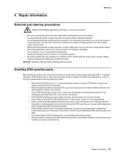
... do not put unprotected ESD-sensitive parts on a table. • If possible, keep all the usual precautions, such as turning off power before removing electronic cards: • Keep the ESD-sensitive part in its covers removed, use parts that are electrical grounds. Repair information 5022... path from being accidentally touched by other personnel. They increase the risk of electrical parts or high-voltage parts such as the high-voltage power supply. • After part replacement, ensure the wiring harness is not caught or damaged. • Do not attempt to cut or extend ...
... do not put unprotected ESD-sensitive parts on a table. • If possible, keep all the usual precautions, such as turning off power before removing electronic cards: • Keep the ESD-sensitive part in its covers removed, use parts that are electrical grounds. Repair information 5022... path from being accidentally touched by other personnel. They increase the risk of electrical parts or high-voltage parts such as the high-voltage power supply. • After part replacement, ensure the wiring harness is not caught or damaged. • Do not attempt to cut or extend ...

Service Manual
Page 164
Rear Left side 13. Repair information 4-31 Lift and remove the top access cover assembly. On the left side, unplug the connector (J) from the rear. 5022-xxx D 11. 10. Remove the screw (D) from CN1 on the high voltage power supply (HVPS). Disconnect the cables for the fan at JFAN1 (E), the operator panel at JOPP1 (F), the high voltage power supply connector at JHVPS1 (G), and the bin full sensor at JBIN1(H) (for network printers only) from the system card. 12.
Rear Left side 13. Repair information 4-31 Lift and remove the top access cover assembly. On the left side, unplug the connector (J) from the rear. 5022-xxx D 11. 10. Remove the screw (D) from CN1 on the high voltage power supply (HVPS). Disconnect the cables for the fan at JFAN1 (E), the operator panel at JOPP1 (F), the high voltage power supply connector at JHVPS1 (G), and the bin full sensor at JBIN1(H) (for network printers only) from the system card. 12.


