
User's Guide
Page 30
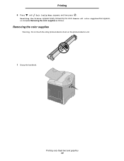
Removing the color supplies Warning: Do not touch the shiny photoconductor drum on the photoconductor unit. 1 Grasp the handhold. Printing only black text and graphics 30 Remove all color supplies then appears, so complete Removing the color supplies as follows. Resetting the Printer appears briefly, followed by the clock. Printing 6 Press until Exit Config Menu appears, and then press .
Removing the color supplies Warning: Do not touch the shiny photoconductor drum on the photoconductor unit. 1 Grasp the handhold. Printing only black text and graphics 30 Remove all color supplies then appears, so complete Removing the color supplies as follows. Resetting the Printer appears briefly, followed by the clock. Printing 6 Press until Exit Config Menu appears, and then press .
User's Guide
Page 31
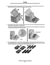
... the handle on the right shows, all three color photoconductor units must be seen. 3 Grasp the knob on replacement photoconductor units) to the shiny photoconductor drum. 1 2 Printing only black text and graphics 31
... the handle on the right shows, all three color photoconductor units must be seen. 3 Grasp the knob on replacement photoconductor units) to the shiny photoconductor drum. 1 2 Printing only black text and graphics 31
User's Guide
Page 81
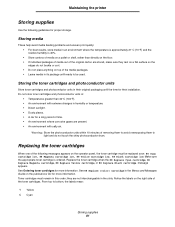
... photoconductor units Store toner cartridges and photoconductor units in the slots. they rest on a flat surface so the edges do not touch the shiny photoconductor drum. Storing media These help avoid media feeding problems and uneven print quality: • For best results, store media in its package until the time for...
... photoconductor units Store toner cartridges and photoconductor units in the slots. they rest on a flat surface so the edges do not touch the shiny photoconductor drum. Storing media These help avoid media feeding problems and uneven print quality: • For best results, store media in its package until the time for...
Service Manual
Page 75
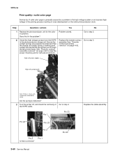
... No 1 Replace the photoconductor unit for removal procedures. Go to view the proper mounting and for the color in toner development on the entire photoconductor drum. Problem solved. Pin 1 Pin 23 Pin 24 Pin 23 Pin 2 Pin 2 Is there continuity?
... No 1 Replace the photoconductor unit for removal procedures. Go to view the proper mounting and for the color in toner development on the entire photoconductor drum. Problem solved. Pin 1 Pin 23 Pin 24 Pin 23 Pin 2 Pin 2 Is there continuity?
Service Manual
Page 111
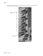
Photoconductor drums Transfer belt 3-34 Service Manual 5022-xxx Once the paper is fed onto the transfer belt, the photoconductor drums in conjunction with the transfer belt pull the print media through the paper path.
Photoconductor drums Transfer belt 3-34 Service Manual 5022-xxx Once the paper is fed onto the transfer belt, the photoconductor drums in conjunction with the transfer belt pull the print media through the paper path.
Service Manual
Page 122
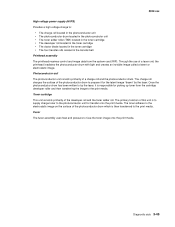
... the surface of this unit is responsible for picking up toner from the system card (RIP). The primary function of the photoconductor drum to prepare it is to supply charge toner to the photoconductor unit for the latent image "drawn" by the laser. Toner cartridge ...High voltage power supply (HVPS) Provides a high voltage charge to: • The charge roll located in the photoconductor unit • The photoconductor drum located in the photoconductor unit • The toner adder roller (TAR) located in the toner cartridge • The developer roll located in the toner...
... the surface of this unit is responsible for picking up toner from the system card (RIP). The primary function of the photoconductor drum to prepare it is to supply charge toner to the photoconductor unit for the latent image "drawn" by the laser. Toner cartridge ...High voltage power supply (HVPS) Provides a high voltage charge to: • The charge roll located in the photoconductor unit • The photoconductor drum located in the photoconductor unit • The toner adder roller (TAR) located in the toner cartridge • The developer roll located in the toner...
Service Manual
Page 123
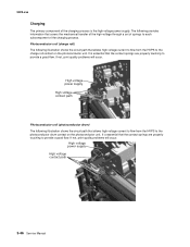
... (charge roll) The following illustration shows the circuit path that allows high voltage current to flow from the HVPS to the photoconductor drum contact on the photoconductor unit. It is essential that covers the mechanical transfer of the high voltage through a set of springs to...subcomponent of the charging process is the high voltage power supply. High voltage power supply High voltage contact path Photoconductor unit (photoconductor drum) The following provides information that the contact springs are properly touching to the charge roll contact on the photoconductor unit. It is...
... (charge roll) The following illustration shows the circuit path that allows high voltage current to flow from the HVPS to the photoconductor drum contact on the photoconductor unit. It is essential that covers the mechanical transfer of the high voltage through a set of springs to...subcomponent of the charging process is the high voltage power supply. High voltage power supply High voltage contact path Photoconductor unit (photoconductor drum) The following provides information that the contact springs are properly touching to the charge roll contact on the photoconductor unit. It is...
Service Manual
Page 125
5022-xxx Transfer belt The transfer belt houses four transfer rollers that provide image transfer from the photoconductor drum to the print media. Transfer belt high voltage path 3-48 Service Manual The transfer belt receives its high voltage charge through spring contacts located on the transfer contact assembly as well. For the sake of simplicity, only one of the roller's high voltage paths is typical for the other three rollers as shown in the following illustration. This path is shown.
5022-xxx Transfer belt The transfer belt houses four transfer rollers that provide image transfer from the photoconductor drum to the print media. Transfer belt high voltage path 3-48 Service Manual The transfer belt receives its high voltage charge through spring contacts located on the transfer contact assembly as well. For the sake of simplicity, only one of the roller's high voltage paths is typical for the other three rollers as shown in the following illustration. This path is shown.
Service Manual
Page 127
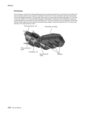
...primary components of the difference in electrical charge between the toner adder roll and the developer roll. Photoconductor unit Developer cartridge Photoconductor drum Developer roll Toner add roll (TAR) Paddles 3-50 Service Manual The toner uniformly coats the developer roll with help from the... three paddle assemblies. The toner on the toner adder roll is then electrically attracted to the electrostatic image on the photoconductor drum. Toner is introduced to the developer roll because of the developing process are the photoconductor unit and the toner cartridge. The...
...primary components of the difference in electrical charge between the toner adder roll and the developer roll. Photoconductor unit Developer cartridge Photoconductor drum Developer roll Toner add roll (TAR) Paddles 3-50 Service Manual The toner uniformly coats the developer roll with help from the... three paddle assemblies. The toner on the toner adder roll is then electrically attracted to the electrostatic image on the photoconductor drum. Toner is introduced to the developer roll because of the developing process are the photoconductor unit and the toner cartridge. The...
Service Manual
Page 128
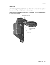
... transfer roll(s) located inside the transfer belt pulls the image from the photoconductor drum to provide transport for transfer onto the print media. Photoconductor unit Photoconductor drum Transfer roll Diagnostic aids 3-51 Toner is not transferred directly to the photoconductor drum, the image is ready for the print media. This is carried along...
... transfer roll(s) located inside the transfer belt pulls the image from the photoconductor drum to provide transport for transfer onto the print media. Photoconductor unit Photoconductor drum Transfer roll Diagnostic aids 3-51 Toner is not transferred directly to the photoconductor drum, the image is ready for the print media. This is carried along...
Service Manual
Page 130
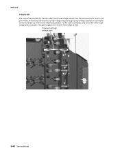
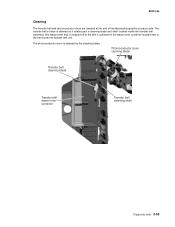
... cleaned at the end of the belt is collected in the waste toner container located next to the belt inside the transfer belt assembly. Photoconductor drum cleaning blade Transfer belt cleaning blade Transfer belt waste toner container Transfer belt cleaning shaft Diagnostic aids 3-53 The transfer belt surface is cleaned by...
... cleaned at the end of the belt is collected in the waste toner container located next to the belt inside the transfer belt assembly. Photoconductor drum cleaning blade Transfer belt cleaning blade Transfer belt waste toner container Transfer belt cleaning shaft Diagnostic aids 3-53 The transfer belt surface is cleaned by...
Service Manual
Page 149
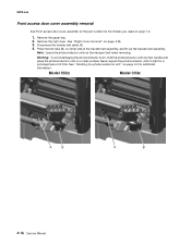
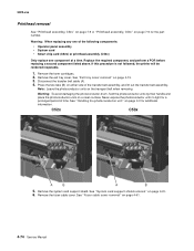
... photoconductor units to light for a prolonged period of the transfer belt assembly, and lift out the transfer belt assembly. Warning: To avoid damaging the photoconductor drum, hold the photoconductor units by their handle and place the photoconductor units on page 4-26. 3. Model C52x Model C53x A B A B 4-16 Service Manual Press the two...
... photoconductor units to light for a prolonged period of the transfer belt assembly, and lift out the transfer belt assembly. Warning: To avoid damaging the photoconductor drum, hold the photoconductor units by their handle and place the photoconductor units on page 4-26. 3. Model C52x Model C53x A B A B 4-16 Service Manual Press the two...
Service Manual
Page 203
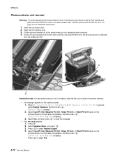
... printer, ensuring the left end of the photoconductor unit, releasing from the holding pin (B). 5022-xxx Photoconductor unit removal Warning: To avoid damaging the photoconductor drum, hold the photoconductor units by their handle and place the photoconductor units on page 4-2 for additional information. 1. Replace Supply displays. 2. When 84 PC Unit Life...
... printer, ensuring the left end of the photoconductor unit, releasing from the holding pin (B). 5022-xxx Photoconductor unit removal Warning: To avoid damaging the photoconductor drum, hold the photoconductor units by their handle and place the photoconductor units on page 4-2 for additional information. 1. Replace Supply displays. 2. When 84 PC Unit Life...

Service Manual
Page 207
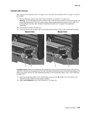
... inoperable. 1. Never expose the photoconductor units to light for the part number. C52x C53x A B A B 5. Disconnect the transfer belt cable (A). 4. Warning: To avoid damaging the photoconductor drum, hold the photoconductor units by their handle and place the photoconductor units on page 4-2 for additional information. See "Handing the photoconductor unit" on a clean surface...
... inoperable. 1. Never expose the photoconductor units to light for the part number. C52x C53x A B A B 5. Disconnect the transfer belt cable (A). 4. Warning: To avoid damaging the photoconductor drum, hold the photoconductor units by their handle and place the photoconductor units on page 4-2 for additional information. See "Handing the photoconductor unit" on a clean surface...
Service Manual
Page 224
... notes: When you installed the new transfer belt and moved all photoconductor units. See "Color Alignment" on page 4-70. Warning: To avoid damaging the photoconductor drum, hold release the buttons when the clock graphic displays.) 2. See "Handing the photoconductor unit" on page 4-2 for the part number. 1. See "Photoconductor unit removal" on...
... notes: When you installed the new transfer belt and moved all photoconductor units. See "Color Alignment" on page 4-70. Warning: To avoid damaging the photoconductor drum, hold release the buttons when the clock graphic displays.) 2. See "Handing the photoconductor unit" on page 4-2 for the part number. 1. See "Photoconductor unit removal" on...

Service Manual
Page 243
..." on either side of time. Press the two tabs (B) on page 4-26. 3. Model C52x Model C53x A B A B 4-16 Service Manual Warning: To avoid damaging the photoconductor drum, hold the photoconductor units by their handle and place the photoconductor units on page 4-2 for a prolonged period of the transfer belt assembly, and lift out...
..." on either side of time. Press the two tabs (B) on page 4-26. 3. Model C52x Model C53x A B A B 4-16 Service Manual Warning: To avoid damaging the photoconductor drum, hold the photoconductor units by their handle and place the photoconductor units on page 4-2 for a prolonged period of the transfer belt assembly, and lift out...

Service Manual
Page 297
... was just replaced, and then press . Replace Supply displays. 2. Press to select Replace Supply. 4. 5022-xxx Photoconductor unit removal Warning: To avoid damaging the photoconductor drum, hold the photoconductor units by their handle and place the photoconductor units on page 4-2 for additional information. 1. See "Handing the photoconductor unit" on a clean surface...
... was just replaced, and then press . Replace Supply displays. 2. Press to select Replace Supply. 4. 5022-xxx Photoconductor unit removal Warning: To avoid damaging the photoconductor drum, hold the photoconductor units by their handle and place the photoconductor units on page 4-2 for additional information. 1. See "Handing the photoconductor unit" on a clean surface...
Service Manual
Page 301
Warning: To avoid damaging the photoconductor drum, hold the photoconductor units by their handle and place the photoconductor units on page 4-15. 3. Replace the required component, and perform a POR before replacing a second ...
Warning: To avoid damaging the photoconductor drum, hold the photoconductor units by their handle and place the photoconductor units on page 4-15. 3. Replace the required component, and perform a POR before replacing a second ...

Service Manual
Page 318
... transfer belt assembly. See "Color Alignment" on either side of the toner cartridges and photoconductor units may have changed. Warning: To avoid damaging the photoconductor drum, hold release the buttons when the clock graphic displays.) 2. Press the two tabs (B) on page 3-24. See "Color Alignment" on a clean surface. Enter the Configuration...
... transfer belt assembly. See "Color Alignment" on either side of the toner cartridges and photoconductor units may have changed. Warning: To avoid damaging the photoconductor drum, hold release the buttons when the clock graphic displays.) 2. Press the two tabs (B) on page 3-24. See "Color Alignment" on a clean surface. Enter the Configuration...


