
Lexmark 4227 User's Guide
Page 129
...Ribbon Cartridge" on page 4. • Ribbon is twisted or ribbon edge is set incorrectly. Dots are smudged. Nothing is printed on page 4. • AutoGap is set incorrectly. For ...8226; Auto Sheet Feeder is installed and AutoGap is set incorrectly. Action: The printer needs repair. • Ribbon cartridge is not set correctly. For help to remind you of...Printer Problems Symptom Probable Causes and Actions Printing is worn or dry. Tip: Mark the date of the next replacement date. • Ribbon cartridge is not set correctly. Action: Replace the ribbon cartridge. Forms...
...Ribbon Cartridge" on page 4. • Ribbon is twisted or ribbon edge is set incorrectly. Dots are smudged. Nothing is printed on page 4. • AutoGap is set incorrectly. For ...8226; Auto Sheet Feeder is installed and AutoGap is set incorrectly. Action: The printer needs repair. • Ribbon cartridge is not set correctly. For help to remind you of...Printer Problems Symptom Probable Causes and Actions Printing is worn or dry. Tip: Mark the date of the next replacement date. • Ribbon cartridge is not set correctly. Action: Replace the ribbon cartridge. Forms...

Lexmark 4227 User's Guide
Page 147
...defects in material and workmanship, • Conforms to in this statement as "Remarketer." Warranty Lexmark warrants that this machine: • Is manufactured from new parts, or new and serviceable used...repair without charge. 141 Appendix B: Statement of Limited Warranty If this machine does not function as warranted during the warranty period, contact a Remarketer or Lexmark, who is subject to these terms only if located in good working order. Statement of Limited Warranty Statement of Limited Warranty Appendix B Lexmark International, Inc., Lexington, KY Lexmark 4227 Forms Printer...
...defects in material and workmanship, • Conforms to in this statement as "Remarketer." Warranty Lexmark warrants that this machine: • Is manufactured from new parts, or new and serviceable used...repair without charge. 141 Appendix B: Statement of Limited Warranty If this machine does not function as warranted during the warranty period, contact a Remarketer or Lexmark, who is subject to these terms only if located in good working order. Statement of Limited Warranty Statement of Limited Warranty Appendix B Lexmark International, Inc., Lexington, KY Lexmark 4227 Forms Printer...

Lexmark 4227 User's Guide
Page 148
... of any legal obligation or restrictions that user for the remainder of the warranty period. Also, such machine must be a new or repaired item. If you transfer this machine to another user, warranty service under the terms of original purchase. Warranty service will be required to... Limited Warranty Replacement is not available to that prevent its exchange. The replacement item assumes the remaining warranty period of the Remarketer or Lexmark. Before you may be required to that feature or accessory is used with such machine. To obtain warranty service, you present for ...
... of any legal obligation or restrictions that user for the remainder of the warranty period. Also, such machine must be a new or repaired item. If you transfer this machine to another user, warranty service under the terms of original purchase. Warranty service will be required to... Limited Warranty Replacement is not available to that prevent its exchange. The replacement item assumes the remaining warranty period of the Remarketer or Lexmark. Before you may be required to that feature or accessory is used with such machine. To obtain warranty service, you present for ...

Lexmark 4227 User's Guide
Page 149
... of Limited Warranty NO WARRANTIES, EXPRESS OR IMPLIED, WILL APPLY AFTER THIS PERIOD. This is legally liable. Warranty service does not include repair of the machine by you advise Lexmark or a Remarketer of the possibility of a machine. Statement of Limited Warranty Extent of Warranty We do not warrant uninterrupted or error-free...
... of Limited Warranty NO WARRANTIES, EXPRESS OR IMPLIED, WILL APPLY AFTER THIS PERIOD. This is legally liable. Warranty service does not include repair of the machine by you advise Lexmark or a Remarketer of the possibility of a machine. Statement of Limited Warranty Extent of Warranty We do not warrant uninterrupted or error-free...

Lexmark 4227 Plus User's Guide
Page 114
Dots are smudged. Solving Printer ...Problems Symptom Printing is not set correctly. Tip: Mark the date of the next replacement date. • Ribbon cartridge is too light or blurred. Action: Reset the ribbon cartridge correctly. For help, see "Installing the Ribbon Cartridge" on page 3. • Printhead is folded. Action: Replace the ribbon cartridge. Forms... 35). 108 Chapter 6: Solving Printer Problems For help , see "Installing the Ribbon Cartridge" on page 3. • AutoGap is set correctly. Action: The printer needs repair. • Ribbon cartridge is...
Dots are smudged. Solving Printer ...Problems Symptom Printing is not set correctly. Tip: Mark the date of the next replacement date. • Ribbon cartridge is too light or blurred. Action: Reset the ribbon cartridge correctly. For help, see "Installing the Ribbon Cartridge" on page 3. • Printhead is folded. Action: Replace the ribbon cartridge. Forms... 35). 108 Chapter 6: Solving Printer Problems For help , see "Installing the Ribbon Cartridge" on page 3. • AutoGap is set correctly. Action: The printer needs repair. • Ribbon cartridge is...

Lexmark 4227 Plus User's Guide
Page 124
...additional suggestions. Note: To assure compliance with FCC regulations on the approximation and harmonization of the laws of Manufacturing and Technical Support, Lexmark International, S.A., Boigny, France. European Community (EC) Directives Conformity This product is in conformity with this symbol , it MUST ...of the Member States relating to an elec- trical outlet that is near the product and easily accessible. • Refer service or repairs, other than those described in the operating instructions, to a professional service person. • This product is not responsible for a ...
...additional suggestions. Note: To assure compliance with FCC regulations on the approximation and harmonization of the laws of Manufacturing and Technical Support, Lexmark International, S.A., Boigny, France. European Community (EC) Directives Conformity This product is in conformity with this symbol , it MUST ...of the Member States relating to an elec- trical outlet that is near the product and easily accessible. • Refer service or repairs, other than those described in the operating instructions, to a professional service person. • This product is not responsible for a ...

Lexmark 4227 Plus User's Guide
Page 129
Statement of Limited Warranty Appendix B Statement of Limited Warranty Lexmark International, Inc., Lexington, KY Lexmark 4227 plus Forms Printer This Statement of original purchase as shown on the date of Limited Warranty applies to this machine if it was purchased. The warranty...; Is free from whom the machine was designed. If this statement is subject to present the feature or accessory with the machine for its repair without charge. Warranty service will be required to these terms only if located in the country of original purchase. When warranty service involves the ...
Statement of Limited Warranty Appendix B Statement of Limited Warranty Lexmark International, Inc., Lexington, KY Lexmark 4227 plus Forms Printer This Statement of original purchase as shown on the date of Limited Warranty applies to this machine if it was purchased. The warranty...; Is free from whom the machine was designed. If this statement is subject to present the feature or accessory with the machine for its repair without charge. Warranty service will be required to these terms only if located in the country of original purchase. When warranty service involves the ...

Lexmark 4227 Plus User's Guide
Page 130
.... Such developer is true even if you advise Lexmark or a Remarketer of the possibility of such damages. You may recover actual damages up to the limit set forth in warranty service, or damaged beyond repair. Free remote technical support is provided for this product...the machine you present for exchange is defaced, altered, in need of a repair not included in this section. If such laws apply, the limitations or exclusions contained in other than a Remarketer or Lexmark, or failure caused by misuse, accident, modification, unsuitable physical or operating environment...
.... Such developer is true even if you advise Lexmark or a Remarketer of the possibility of such damages. You may recover actual damages up to the limit set forth in warranty service, or damaged beyond repair. Free remote technical support is provided for this product...the machine you present for exchange is defaced, altered, in need of a repair not included in this section. If such laws apply, the limitations or exclusions contained in other than a Remarketer or Lexmark, or failure caused by misuse, accident, modification, unsuitable physical or operating environment...

Service Manual
Page 4
4227-300 Operator panel service check 2-20 Paper feed service check 2-21 POST service check 2-24 Power failure service check 2-25 Print quality service ... 3-3 Service Menu 3-3 Button Test 3-4 Factory Setting 3-4 Printhead Bank 3-4 Jam/PSet Sensor Test 3-4 Impact force 3-4 Log clear 3-4 Print Test 3-5 Other print tests 3-5 Error log 3-5 Repair information 4-1 Handling ESD-sensitive parts 4-1 Adjustments 4-2 Printhead installation adjustment 4-2 Printhead-to-platen gap adjustment 4-2 Bidirectional print adjustment 4-3 Removals 4-5 Top cover removal 4-5 Auto Gap motor removal...
4227-300 Operator panel service check 2-20 Paper feed service check 2-21 POST service check 2-24 Power failure service check 2-25 Print quality service ... 3-3 Service Menu 3-3 Button Test 3-4 Factory Setting 3-4 Printhead Bank 3-4 Jam/PSet Sensor Test 3-4 Impact force 3-4 Log clear 3-4 Print Test 3-5 Other print tests 3-5 Error log 3-5 Repair information 4-1 Handling ESD-sensitive parts 4-1 Adjustments 4-2 Printhead installation adjustment 4-2 Printhead-to-platen gap adjustment 4-2 Bidirectional print adjustment 4-3 Removals 4-5 Top cover removal 4-5 Auto Gap motor removal...
Service Manual
Page 12
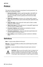
...general description of the MFP and the maintenance approach used to isolate failing field replaceable units (FRUs). 3. Repair information provides instructions for service personnel. Definitions Note: A note provides additional information. Unplug the product before you...the lubrication specifications and recommendations to identify the connector locations and test points on the printer. 6. xi Service Manual Connector locations uses illustrations to prevent problems. 7. 4227-300 Preface This manual contains maintenance procedures for making MFP adjustments and removing and ...
...general description of the MFP and the maintenance approach used to isolate failing field replaceable units (FRUs). 3. Repair information provides instructions for service personnel. Definitions Note: A note provides additional information. Unplug the product before you...the lubrication specifications and recommendations to identify the connector locations and test points on the printer. 6. xi Service Manual Connector locations uses illustrations to prevent problems. 7. 4227-300 Preface This manual contains maintenance procedures for making MFP adjustments and removing and ...

Service Manual
Page 15
4227-300 Maintenance approach The diagnostic information in .) • Analog or digital volt-ohmmeter General information 1-3 Use the error indication table, symptom/check table, service checks ... Phillips screwdriver • #2 magnetic Phillips screwdriver • Feeler gauges 0.35 mm (0.014 in.) 0.4 mm (0.016 in this manual leads you to determine the symptom and repair the failure. Begin with "Power-On Self Test (POST)" on page 3-1.
4227-300 Maintenance approach The diagnostic information in .) • Analog or digital volt-ohmmeter General information 1-3 Use the error indication table, symptom/check table, service checks ... Phillips screwdriver • #2 magnetic Phillips screwdriver • Feeler gauges 0.35 mm (0.014 in.) 0.4 mm (0.016 in this manual leads you to determine the symptom and repair the failure. Begin with "Power-On Self Test (POST)" on page 3-1.

Service Manual
Page 65
4227-300 4. Connect the wrist band to remove defective parts. If you are removing a pluggable module, use parts that are ready to install the part into its special bag. • Machine covers and metal tables are not working with your body to electrostatic discharge (ESD). Repair information This chapter ... it into the machine. • Make as few movements as possible with ESD-sensitive parts when cold- if you are electrical grounds. Repair information 4-1 Install machine covers when you need to prevent an increase of damage because they make adjustments to the...
4227-300 4. Connect the wrist band to remove defective parts. If you are removing a pluggable module, use parts that are ready to install the part into its special bag. • Machine covers and metal tables are not working with your body to electrostatic discharge (ESD). Repair information This chapter ... it into the machine. • Make as few movements as possible with ESD-sensitive parts when cold- if you are electrical grounds. Repair information 4-1 Install machine covers when you need to prevent an increase of damage because they make adjustments to the...

Service Manual
Page 67
4227-300 Printhead-to save the setting in NVRAM. Press Store to -platen gap electronic setting Be sure there is in the printer. 1. The following steps tell how to ... (unidirectional). Remove the ribbon guide. 4. The gap specification is within the specification. 10. Load continuous forms. 2. Install a ribbon. 2. Hold down FormFeed and power on the display. 4. The Micro↑... and uses a line length corresponding to -platen gap setting. 8. Press Next →. 5. Repair information 4-3 Measure the printhead-to -platen gap setting. Run the test at both the Draft ...
4227-300 Printhead-to save the setting in NVRAM. Press Store to -platen gap electronic setting Be sure there is in the printer. 1. The following steps tell how to ... (unidirectional). Remove the ribbon guide. 4. The gap specification is within the specification. 10. Load continuous forms. 2. Install a ribbon. 2. Hold down FormFeed and power on the display. 4. The Micro↑... and uses a line length corresponding to -platen gap setting. 8. Press Next →. 5. Repair information 4-3 Measure the printhead-to -platen gap setting. Run the test at both the Draft ...

Service Manual
Page 69
Remove the front cover (1). 4. Remove the acoustic and ribbon access covers (2). 5. Repair information 4-5 4227-300 Removals Use the following procedures to unplug the power cord whenever you are working on the printer with any of the covers removed. 1. Turn the printer off. 2. Disconnect the power cord and parallel cable at the printer. 3. Top cover removal CAUTION: Be sure to remove and replace individual FRUs. Set the Paper Select lever to the cut sheet position.
Remove the front cover (1). 4. Remove the acoustic and ribbon access covers (2). 5. Repair information 4-5 4227-300 Removals Use the following procedures to unplug the power cord whenever you are working on the printer with any of the covers removed. 1. Turn the printer off. 2. Disconnect the power cord and parallel cable at the printer. 3. Top cover removal CAUTION: Be sure to remove and replace individual FRUs. Set the Paper Select lever to the cut sheet position.

Service Manual
Page 71
Repair information 4-7 While lifting the top cover slightly, disconnect the operator panel cable from the main logic board, and then remove the top cover. To Reinstall: ... to crimp or pinch this cable while reinstalling the top cover. 4227-300 9. Be sure not to the operator panel cable may cause failure of other electrical components of the covers removed. Place the printer on the printer with one of the printer. CAUTION: Be sure to unplug the power cord whenever you are...
Repair information 4-7 While lifting the top cover slightly, disconnect the operator panel cable from the main logic board, and then remove the top cover. To Reinstall: ... to crimp or pinch this cable while reinstalling the top cover. 4227-300 9. Be sure not to the operator panel cable may cause failure of other electrical components of the covers removed. Place the printer on the printer with one of the printer. CAUTION: Be sure to unplug the power cord whenever you are...

Service Manual
Page 73
Remove the right cover (1). 2. Repair information 4-9 4227-300 Auto Sheet Feeder gears removal 1. Release the latch, and then remove the pick-up gear (4). 5. Remove the latch, and then remove the idler gear (3). 4. Release the latch, and then remove the joint gear (2). 3. Release the latch, and then remove the combination lock mechanism (5).
Remove the right cover (1). 2. Repair information 4-9 4227-300 Auto Sheet Feeder gears removal 1. Release the latch, and then remove the pick-up gear (4). 5. Remove the latch, and then remove the idler gear (3). 4. Release the latch, and then remove the joint gear (2). 3. Release the latch, and then remove the combination lock mechanism (5).

Service Manual
Page 75
Remove the print unit. 4. If you . 3. Turn the printer so the rear of the printer faces you are replacing the bottom cover, write the machine serial number and part number on page 4-5. 3. Manipulate the left side of the tension pulley ... removal" on the blank label. Remove the tractor cable and bracket. 7. Remove the top cover. Remove both tension pulley plate mounting screws (1). 4. Base assembly removal 1. Repair information 4-11 See "Top cover removal" on page 4-5. 2. Remove the main logic board. 6. Slide the pulley plate to the right and off the lug...
Remove the print unit. 4. If you . 3. Turn the printer so the rear of the printer faces you are replacing the bottom cover, write the machine serial number and part number on page 4-5. 3. Manipulate the left side of the tension pulley ... removal" on the blank label. Remove the tractor cable and bracket. 7. Remove the top cover. Remove both tension pulley plate mounting screws (1). 4. Base assembly removal 1. Repair information 4-11 See "Top cover removal" on page 4-5. 2. Remove the main logic board. 6. Slide the pulley plate to the right and off the lug...

Service Manual
Page 77
Push the pulley up on both sides of the belt to free the carrier belt. Pull up and remove it to move the tension pulley plate as far as possible toward the outside of the printer and remove its shaft through the large part of the printer, and then retighten the large screw. 7. Remove the belt from the carrier motor pulley. 8. 4227-300 6. Loosen the two tension pulley plate screws (2). Repair information 4-13 Push the tension pulley toward the center of the keyhole.
Push the pulley up on both sides of the belt to free the carrier belt. Pull up and remove it to move the tension pulley plate as far as possible toward the outside of the printer and remove its shaft through the large part of the printer, and then retighten the large screw. 7. Remove the belt from the carrier motor pulley. 8. 4227-300 6. Loosen the two tension pulley plate screws (2). Repair information 4-13 Push the tension pulley toward the center of the keyhole.

Service Manual
Page 79
... tighten the ribbon motor assembly mounting screws. See "Top cover removal" on both sides of the printer, and then retighten the large screw. 4. Loosen the two tension pulley plate screws. Pull up on page 4-5. 2. 4227-300 Carrier motor assembly removal 1. Disconnect carrier motor connectors CN9 and CN15 from the main logic board... to its bracket. 5. Be sure the motor pulley goes inside the belt as possible toward the center of the belt to the carrier motor shaft. 3. Repair information 4-15 Remove the carrier motor.
... tighten the ribbon motor assembly mounting screws. See "Top cover removal" on both sides of the printer, and then retighten the large screw. 4. Loosen the two tension pulley plate screws. Pull up on page 4-5. 2. 4227-300 Carrier motor assembly removal 1. Disconnect carrier motor connectors CN9 and CN15 from the main logic board... to its bracket. 5. Be sure the motor pulley goes inside the belt as possible toward the center of the belt to the carrier motor shaft. 3. Repair information 4-15 Remove the carrier motor.

Service Manual
Page 81
Remove the support bracket (1) from behind with a flat-blade screwdriver. 6. 4227-300 Lower feed roller removal 1. Remove the paper feed motor. 5. Remove the Paper Select lever. Remove the print unit. 3. Remove the sub logic board. 4. Remove the large gear from the left side frame by prying it from the back of the platen. 7. Repair information 4-17 See "Top cover removal" on page 4-5. 2. Remove the top cover.
Remove the support bracket (1) from behind with a flat-blade screwdriver. 6. 4227-300 Lower feed roller removal 1. Remove the paper feed motor. 5. Remove the Paper Select lever. Remove the print unit. 3. Remove the sub logic board. 4. Remove the large gear from the left side frame by prying it from the back of the platen. 7. Repair information 4-17 See "Top cover removal" on page 4-5. 2. Remove the top cover.