
Service Manual
Page 30
... the computer or interface cable. Abnormal Noise Problems Symptom During POST, abnormal noise comes from the printer. Action Disconnect the interface cable from the printer and turn off and then on page 2-31. Action Check the ribbon cartridge for binds or damage. Abnormal Indications Symptom 7 or more lights turn on but POST will...
... the computer or interface cable. Abnormal Noise Problems Symptom During POST, abnormal noise comes from the printer. Action Disconnect the interface cable from the printer and turn off and then on page 2-31. Action Check the ribbon cartridge for binds or damage. Abnormal Indications Symptom 7 or more lights turn on but POST will...

Service Manual
Page 38
... the carrier motor connector CN9 from the main logic board. Disconnect the paper feed motor from CN10 from the main logic board, and turn the printer off and then on. Run the print test (do not fold or damage the cables during the test). Replace the printhead if the noise is... If the abnormal noise is gone, look for a problem with the carrier motor or ribbon drive mechanism. If the abnormal noise is gone. FRU 1 Ribbon Cartridge 2 Printhead 3 Carrier Motor Ribbon Drive Mechanism 4 Paper Feed Mechanism Action Remove and reinstall the ribbon...
... the carrier motor connector CN9 from the main logic board. Disconnect the paper feed motor from CN10 from the main logic board, and turn the printer off and then on. Run the print test (do not fold or damage the cables during the test). Replace the printhead if the noise is... If the abnormal noise is gone, look for a problem with the carrier motor or ribbon drive mechanism. If the abnormal noise is gone. FRU 1 Ribbon Cartridge 2 Printhead 3 Carrier Motor Ribbon Drive Mechanism 4 Paper Feed Mechanism Action Remove and reinstall the ribbon...

Service Manual
Page 45
...check all feed roller surfaces. • Clean the ribbon shield and printhead. • Clean the platen surface. • Install the ribbon cartridge correctly. • If the ribbon end of the voltages is within tolerance. 2. Disconnect the power supply cable from the paper path. &#...dc ±5%) & CP1-4 (Signal GND) If one of life has been reached, have the customer replace the ribbon cartridge. Action The cause of the power cord. 3. Turn the printer power on the sub logic board. Diagnostic Information 2-21 Be sure the output voltages are incorrect, replace the power supply...
...check all feed roller surfaces. • Clean the ribbon shield and printhead. • Clean the platen surface. • Install the ribbon cartridge correctly. • If the ribbon end of the voltages is within tolerance. 2. Disconnect the power supply cable from the paper path. &#...dc ±5%) & CP1-4 (Signal GND) If one of life has been reached, have the customer replace the ribbon cartridge. Action The cause of the power cord. 3. Turn the printer power on the sub logic board. Diagnostic Information 2-21 Be sure the output voltages are incorrect, replace the power supply...

Service Manual
Page 77
... [1] of the left of 0.35 mm and 0.40 mm (0.014 in .) feeler gauge. Turn the printer off. 2. 1. Move the carrier so that it is between the printhead [3] and platen [4] is just to position 1. 5. Remove the ribbon cartridge and paper. 4. Set the form thickness lever to the left upper feed roller, approximately 50...
... [1] of the left of 0.35 mm and 0.40 mm (0.014 in .) feeler gauge. Turn the printer off. 2. 1. Move the carrier so that it is between the printhead [3] and platen [4] is just to position 1. 5. Remove the ribbon cartridge and paper. 4. Set the form thickness lever to the left upper feed roller, approximately 50...

Service Manual
Page 79
... from left . Press Alt and then press Micro↑ . Press the Control Options button. (Button varies with model.) 6. Be sure the ribbon cartridge and continuous forms are printed from right to left to right. Press Font. The first and third lines are installed. 2. Repair Information 4-5 Bidirectional Print... Adjustment After replacing any mechanical part which affects the operation of paper, so be completed if the printer runs out of the main logic board or the carrier, perform the following procedure to use continuous forms. 1. The...
... from left . Press Alt and then press Micro↑ . Press the Control Options button. (Button varies with model.) 6. Be sure the ribbon cartridge and continuous forms are printed from right to left to right. Press Font. The first and third lines are installed. 2. Repair Information 4-5 Bidirectional Print... Adjustment After replacing any mechanical part which affects the operation of paper, so be completed if the printer runs out of the main logic board or the carrier, perform the following procedure to use continuous forms. 1. The...

Service Manual
Page 122
... printhead up and remove. Disconnect the power cord at the printer. • Let the printhead cool for the ribbon cartridge to -Platen Gap Adjustment procedure, see "Bidirectional Print Adjustment" on page 4-5. 4-48 Remove the ribbon cartridge. 6. If necessary gently pry the printhead upward with a ...3. Reassembly Note: Be sure the printhead cables are correctly aligned and secured. Remove the ribbon access cover. 5. Turn the printer off. 2. Before you remove the printhead, set the form thickness lever to position 7. 4. Printhead Removal 1. Disconnect the printhead cables [2]...
... printhead up and remove. Disconnect the power cord at the printer. • Let the printhead cool for the ribbon cartridge to -Platen Gap Adjustment procedure, see "Bidirectional Print Adjustment" on page 4-5. 4-48 Remove the ribbon cartridge. 6. If necessary gently pry the printhead upward with a ...3. Reassembly Note: Be sure the printhead cables are correctly aligned and secured. Remove the ribbon access cover. 5. Turn the printer off. 2. Before you remove the printhead, set the form thickness lever to position 7. 4. Printhead Removal 1. Disconnect the printhead cables [2]...

Service Manual
Page 141
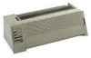
Reference A B C D E F G H I J K L M N O P Q R S T U V W Part Name Form Thickness Lever Paper Select Lever Carrier Motor Paper Feed Motor Parallel Interface Connector Main Logic Board Sub Logic Board Power Supply Tractor Unit Pull Tractor Actuator Ribbon Cartridge Ribbon Drive Rack Gear Pinch Roller, Lower Feed Roller, Lower Printhead Printhead Cables Carrier Tension Pulley Plate Feed Roller, Upper Platen Side Frame, Right Side Frame, Left Carrier Plate Connector Locations 5-1 Connector Locations This chapter shows the locations of specific parts of the printer. 5.
Reference A B C D E F G H I J K L M N O P Q R S T U V W Part Name Form Thickness Lever Paper Select Lever Carrier Motor Paper Feed Motor Parallel Interface Connector Main Logic Board Sub Logic Board Power Supply Tractor Unit Pull Tractor Actuator Ribbon Cartridge Ribbon Drive Rack Gear Pinch Roller, Lower Feed Roller, Lower Printhead Printhead Cables Carrier Tension Pulley Plate Feed Roller, Upper Platen Side Frame, Right Side Frame, Left Carrier Plate Connector Locations 5-1 Connector Locations This chapter shows the locations of specific parts of the printer. 5.


