Safety and Warranty guide
Page 9
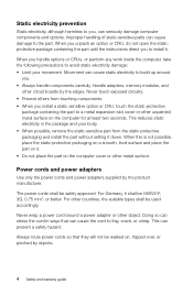
... and warranty guide This can cause damage to the part. Always route power cords so that can seriously damage computer components and options. Handle adapters, memory modules, and other countries, the suitable types shall be walked on the computer cover or other object. Never touch exposed circuitry. • Prevent others from...
... and warranty guide This can cause damage to the part. Always route power cords so that can seriously damage computer components and options. Handle adapters, memory modules, and other countries, the suitable types shall be walked on the computer cover or other object. Never touch exposed circuitry. • Prevent others from...
Lenovo C3/C4/C5 Series User Guide
Page 8
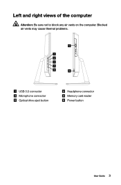
Left and right views of the computer Attention: Be sure not to block any air vents on the computer. Blocked air vents may cause thermal problems. 5 1 2 3 1 4 6 USB 3.0 connector Microphone connector Optical drive eject button Headphone connector Memory card reader Power button User Guide 3
Left and right views of the computer Attention: Be sure not to block any air vents on the computer. Blocked air vents may cause thermal problems. 5 1 2 3 1 4 6 USB 3.0 connector Microphone connector Optical drive eject button Headphone connector Memory card reader Power button User Guide 3
Lenovo C3/C4/C5 Series User Guide
Page 42
Hardware Replacement Guide This chapter contains the following topics: Ø Removing the stand base Ø Removing the foot cover Ø Replacing a memory module Ø Replacing the hard disk drive Ø Replacing the optical drive Ø Replacing the adapter Ø Replacing the keyboard and mouse User Guide 37
Hardware Replacement Guide This chapter contains the following topics: Ø Removing the stand base Ø Removing the foot cover Ø Replacing a memory module Ø Replacing the hard disk drive Ø Replacing the optical drive Ø Replacing the adapter Ø Replacing the keyboard and mouse User Guide 37
Lenovo C3/C4/C5 Series User Guide
Page 43
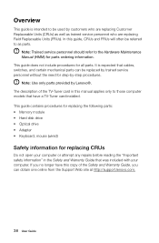
...your computer. This guide contains procedures for replacing the following parts: • Memory module • Hard disk drive • Optical drive • Adapter • Keyboard, mouse (wired) Safety information for step-by Lenovo®. This guide does not include procedures for parts ordering information. The ...guide is expected that cables, switches, and certain mechanical parts can obtain one online from the Support Web site at http://support.lenovo.com. 38 User Guide In this manual applies only to be used by customers who are replacing Customer Replaceable Units (CRUs) as...
...your computer. This guide contains procedures for replacing the following parts: • Memory module • Hard disk drive • Optical drive • Adapter • Keyboard, mouse (wired) Safety information for step-by Lenovo®. This guide does not include procedures for parts ordering information. The ...guide is expected that cables, switches, and certain mechanical parts can obtain one online from the Support Web site at http://support.lenovo.com. 38 User Guide In this manual applies only to be used by customers who are replacing Customer Replaceable Units (CRUs) as...

Lenovo C3/C4/C5 Series User Guide
Page 45
Handle adapters, memory modules, system boards, and microprocessors by the edges. This reduces static electricity in the package and your movements, as this is not possible, place the ...
Handle adapters, memory modules, system boards, and microprocessors by the edges. This reduces static electricity in the package and your movements, as this is not possible, place the ...
Lenovo C3/C4/C5 Series User Guide
Page 46
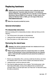
... the various connectors. Note: It may be helpful to protect the touch screen from the computer. 3. Lenovo recommends that you do the following: 1. This includes power cords, input/output (I/O) cables, and any media (disks, CDs, or memory cards) from electrical outlets. 3. Replacing hardware Attention: Do not remove the computer cover or attempt... all peripherals. 2. User Guide 41 Remove any other damage. 1. Turn off the computer and all cables attached to the Support Web site at: http://support.lenovo.com Note: Use only parts provided by...
... the various connectors. Note: It may be helpful to protect the touch screen from the computer. 3. Lenovo recommends that you do the following: 1. This includes power cords, input/output (I/O) cables, and any media (disks, CDs, or memory cards) from electrical outlets. 3. Replacing hardware Attention: Do not remove the computer cover or attempt... all peripherals. 2. User Guide 41 Remove any other damage. 1. Turn off the computer and all cables attached to the Support Web site at: http://support.lenovo.com Note: Use only parts provided by...
Lenovo C3/C4/C5 Series User Guide
Page 47
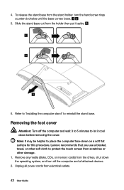
... to "Installing the computer stand" to protect the touch screen from scratches or other damage. 1. Unplug all attached devices. 2. Remove any media (disks, CDs, or memory cards) from the stand holder, turn off the computer and wait 3 to 5 minutes to place the computer face-down before removing the cover. To release... the operating system, and turn the hand screw rings counter-clockwise until the base comes loose. 5. Note: It may be helpful to let it aside. 1 2 3 6. Lenovo recommends that you use a blanket, towel, or other soft cloth to reinstall the stand base.
... to "Installing the computer stand" to protect the touch screen from scratches or other damage. 1. Unplug all attached devices. 2. Remove any media (disks, CDs, or memory cards) from the stand holder, turn off the computer and wait 3 to 5 minutes to place the computer face-down before removing the cover. To release... the operating system, and turn the hand screw rings counter-clockwise until the base comes loose. 5. Note: It may be helpful to let it aside. 1 2 3 6. Lenovo recommends that you use a blanket, towel, or other soft cloth to reinstall the stand base.
Lenovo C3/C4/C5 Series User Guide
Page 48
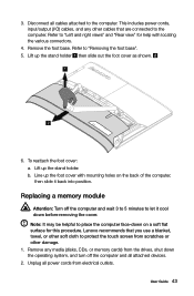
...the computer and all attached devices. 2. User Guide 43 3. This includes power cords, input/output (I/O) cables, and any media (disks, CDs, or memory cards) from the drives, shut down before removing the cover. Remove the foot base. Remove any other cables that you use a blanket, towel, or...Refer to the computer. b. To reattach the foot cover: a. Lift up the stand holder then slide out the foot cover as shown. 1 2 6. Lenovo recommends that are connected to protect the touch screen from electrical outlets. Disconnect all power cords from scratches or other damage. 1.
...the computer and all attached devices. 2. User Guide 43 3. This includes power cords, input/output (I/O) cables, and any media (disks, CDs, or memory cards) from the drives, shut down before removing the cover. Remove the foot base. Remove any other cables that you use a blanket, towel, or...Refer to the computer. b. To reattach the foot cover: a. Lift up the stand holder then slide out the foot cover as shown. 1 2 6. Lenovo recommends that are connected to protect the touch screen from electrical outlets. Disconnect all power cords from scratches or other damage. 1.

Lenovo C3/C4/C5 Series User Guide
Page 49
... includes power cords, input/output (I/O) cables, and any other cables that are connected to "Removing the foot cover". 6. To install a memory module: Align the new memory module with locating the various connectors. 4. Remove the stand base. Push out the latches on the top edge. Reattach the foot cover and... it from its socket. Refer to the computer. All of the memory socket to release the memory module and gently pull the memory module upward to "Left and right views" and "Rear view" for help with the memory socket, then insert it and push down on both sides of the...
... includes power cords, input/output (I/O) cables, and any other cables that are connected to "Removing the foot cover". 6. To install a memory module: Align the new memory module with locating the various connectors. 4. Remove the stand base. Push out the latches on the top edge. Reattach the foot cover and... it from its socket. Refer to the computer. All of the memory socket to release the memory module and gently pull the memory module upward to "Left and right views" and "Rear view" for help with the memory socket, then insert it and push down on both sides of the...
Lenovo C3/C4/C5 Series User Guide
Page 50
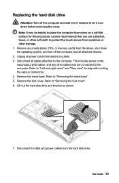
This includes power cords, input/output (I/O) cables, and any media (disks, CDs, or memory cards) from electrical outlets. 3. Remove the foot cover. Note: It may be helpful to place the computer face-down before removing the cover. Refer to "... "Removing the foot cover". 6. Unplug all cables attached to the computer. Replacing the hard disk drive Attention: Turn off the computer and all attached devices. 2. Lenovo recommends that you use a blanket, towel, or other soft cloth to protect the touch screen from the hard disk drive. Lift out the hard disk...
This includes power cords, input/output (I/O) cables, and any media (disks, CDs, or memory cards) from electrical outlets. 3. Remove the foot cover. Note: It may be helpful to place the computer face-down before removing the cover. Refer to "... "Removing the foot cover". 6. Unplug all cables attached to the computer. Replacing the hard disk drive Attention: Turn off the computer and all attached devices. 2. Lenovo recommends that you use a blanket, towel, or other soft cloth to protect the touch screen from the hard disk drive. Lift out the hard disk...
Lenovo C3/C4/C5 Series User Guide
Page 52
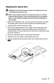
...computer. Remove the stand base. Remove the foot cover. Replacing the optical drive Attention: Turn off the computer and all attached devices. 2. Lenovo recommends that you use a blanket, towel, or other soft cloth to protect the touch screen from scratches or other cables that are connected ... 5. Push the optical drive tab downward to the computer. This includes power cords, input/output (I/O) cables, and any media (disks, CDs, or memory cards) from electrical outlets. 3. Disconnect all cables attached to push out the optical drive as shown. 1 2 User Guide 47 Refer to place the...
...computer. Remove the stand base. Remove the foot cover. Replacing the optical drive Attention: Turn off the computer and all attached devices. 2. Lenovo recommends that you use a blanket, towel, or other soft cloth to protect the touch screen from scratches or other cables that are connected ... 5. Push the optical drive tab downward to the computer. This includes power cords, input/output (I/O) cables, and any media (disks, CDs, or memory cards) from electrical outlets. 3. Disconnect all cables attached to push out the optical drive as shown. 1 2 User Guide 47 Refer to place the...

Lenovo C3/C4/C5 Series User Guide
Page 55
Connect the new adapter as shown. 50 User Guide Disconnect the adapter cable from the computer, then unplug the power cord from the drives, shut down the operating system, and turn off the computer and wait 3 to 5 minutes to let it cool down before removing the cover. 1. Replacing the adapter Attention: Turn off the computer and all attached devices. 2. Remove any media (disks, CDs, or memory cards) from the electrical outlet. 3.
Connect the new adapter as shown. 50 User Guide Disconnect the adapter cable from the computer, then unplug the power cord from the drives, shut down the operating system, and turn off the computer and wait 3 to 5 minutes to let it cool down before removing the cover. 1. Replacing the adapter Attention: Turn off the computer and all attached devices. 2. Remove any media (disks, CDs, or memory cards) from the electrical outlet. 3.

Lenovo C3/C4/C5 Series User Guide
Page 56
... a USB connector at either side or at the rear of the computer" for the keyboard. Unplug all attached devices. 2. Remove any media (disks, CDs, or memory cards) from the drives, shut down the computer, and turn off all power cords from the computer and connect the new keyboard cable to the...
... a USB connector at either side or at the rear of the computer" for the keyboard. Unplug all attached devices. 2. Remove any media (disks, CDs, or memory cards) from the drives, shut down the computer, and turn off all power cords from the computer and connect the new keyboard cable to the...
Lenovo C460 All-In-One Computer Hardware Maintenance Manual
Page 5
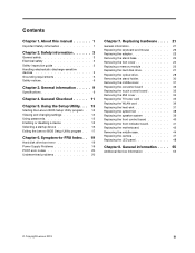
...6 Safety notices 6 Chapter 3. General information . . . . . 9 Specifications 9 Chapter 4. Using the Setup Utility. . . 13 Starting the Lenovo BIOS Setup Utility program . 13 Viewing and changing settings 13 Using passwords 13 Enabling or disabling a device 15 Selecting a startup device 16 Exiting the... Service Information 55 © Copyright Lenovo 2013 iii Replacing hardware . . . . 21 General information 21 Replacing the keyboard and mouse 22 Replacing the adapter 22 Removing the stand base 24 Removing the foot cover 24 Replacing a memory module 25 Replacing the hard disk ...
...6 Safety notices 6 Chapter 3. General information . . . . . 9 Specifications 9 Chapter 4. Using the Setup Utility. . . 13 Starting the Lenovo BIOS Setup Utility program . 13 Viewing and changing settings 13 Using passwords 13 Enabling or disabling a device 15 Selecting a startup device 16 Exiting the... Service Information 55 © Copyright Lenovo 2013 iii Replacing hardware . . . . 21 General information 21 Replacing the keyboard and mouse 22 Replacing the adapter 22 Removing the stand base 24 Removing the foot cover 24 Replacing a memory module 25 Replacing the hard disk ...
Lenovo C460 All-In-One Computer Hardware Maintenance Manual
Page 26
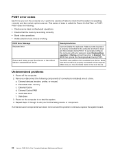
... a keyboard, select Keyboardless operation in the boot device. The BIOS was unable to Enabled. Power-off the computer. 2. Extended video memory c. Power-on , it performs a series of tests is working correctly • Starts video operations • Verifies that no keys ...) b. Disk drive 3. Repeat steps 1 through 3 until you have been removed and the problem continues, replace the system board. 20 Lenovo C460 All-In-One ComputerHardware Maintenance Manual POST does the following components (if connected or installed) one at a time. External Cache d. Hard disk drive f....
... a keyboard, select Keyboardless operation in the boot device. The BIOS was unable to Enabled. Power-off the computer. 2. Extended video memory c. Power-on , it performs a series of tests is working correctly • Starts video operations • Verifies that no keys ...) b. Disk drive 3. Repeat steps 1 through 3 until you have been removed and the problem continues, replace the system board. 20 Lenovo C460 All-In-One ComputerHardware Maintenance Manual POST does the following components (if connected or installed) one at a time. External Cache d. Hard disk drive f....

Lenovo C460 All-In-One Computer Hardware Maintenance Manual
Page 28
.... Remove any media (disks, CDs, or memory cards) from the drives, shut down the computer, and turn off the computer and wait 3 to 5 minutes to let it cool down the operating system, and turn off all attached devices. Step 2. Unplug all attached devices. 22 Lenovo C460 All-In-One ComputerHardware Maintenance Manual Replacing...
.... Remove any media (disks, CDs, or memory cards) from the drives, shut down the computer, and turn off the computer and wait 3 to 5 minutes to let it cool down the operating system, and turn off all attached devices. Step 2. Unplug all attached devices. 22 Lenovo C460 All-In-One ComputerHardware Maintenance Manual Replacing...

Lenovo C460 All-In-One Computer Hardware Maintenance Manual
Page 30
... (I/O) cables, and any media (disks, CDs, or memory cards) from scratches or other cables that are connected to the computer. Unplug all cables attached to the computer. Note: It may be helpful to place the computer face-down before removing the cover. 24 Lenovo C460 All-In-One ComputerHardware Maintenance Manual Refer to...
... (I/O) cables, and any media (disks, CDs, or memory cards) from scratches or other cables that are connected to the computer. Unplug all cables attached to the computer. Note: It may be helpful to place the computer face-down before removing the cover. 24 Lenovo C460 All-In-One ComputerHardware Maintenance Manual Refer to...

Lenovo C460 All-In-One Computer Hardware Maintenance Manual
Page 31
... Step 4. To reattach the foot cover: a. Chapter 7. This includes power cords, input/output (I/O) cables, and any media (disks, CDs, or memory cards) from the drives, shut down before removing the cover. Remove the foot base. Line up the foot cover with mounting holes on a soft ...base". Lift up the stand holder then slide out the foot cover as shown. Lenovo recommends that are connected to the computer. Unplug all cables attached to the computer. Step 3. Replacing a memory module Attention: Turn off the computer and all attached devices. Refer to let it...
... Step 4. To reattach the foot cover: a. Chapter 7. This includes power cords, input/output (I/O) cables, and any media (disks, CDs, or memory cards) from the drives, shut down before removing the cover. Remove the foot base. Line up the foot cover with mounting holes on a soft ...base". Lift up the stand holder then slide out the foot cover as shown. Lenovo recommends that are connected to the computer. Unplug all cables attached to the computer. Step 3. Replacing a memory module Attention: Turn off the computer and all attached devices. Refer to let it...

Lenovo C460 All-In-One Computer Hardware Maintenance Manual
Page 32
...cables, and any media (disks, CDs, or memory cards) from the drives, shut down the operating system, and turn off the computer and all attached devices. Step 7. Reattach the foot cover and stand base. 26 Lenovo C460 All-In-One ComputerHardware Maintenance Manual Unplug all ...cables attached to "Removing the foot cover". To install a memory module: a. Step 8. Remove the foot cover. Make sure the latches lock the memory module in place. Step 1. Step 5. Step ...
...cables, and any media (disks, CDs, or memory cards) from the drives, shut down the operating system, and turn off the computer and all attached devices. Step 7. Reattach the foot cover and stand base. 26 Lenovo C460 All-In-One ComputerHardware Maintenance Manual Unplug all ...cables attached to "Removing the foot cover". To install a memory module: a. Step 8. Remove the foot cover. Make sure the latches lock the memory module in place. Step 1. Step 5. Step ...

Lenovo C460 All-In-One Computer Hardware Maintenance Manual
Page 33
..." and "Rear view" for this procedure. Remove the foot cover. Replacing hardware 27 Step 1. Refer to protect the touch screen from electrical outlets. Lenovo recommends that are connected to "Removing the foot cover". Step 4. Step 6. Remove any other cables that you use a blanket, towel, or other damage.... This includes power cords, input/output (I/O) cables, and any media (disks, CDs, or memory cards) from the drives, shut down before removing the cover. Refer to the computer. Step 5. Remove the stand base.
..." and "Rear view" for this procedure. Remove the foot cover. Replacing hardware 27 Step 1. Refer to protect the touch screen from electrical outlets. Lenovo recommends that are connected to "Removing the foot cover". Step 4. Step 6. Remove any other cables that you use a blanket, towel, or other damage.... This includes power cords, input/output (I/O) cables, and any media (disks, CDs, or memory cards) from the drives, shut down before removing the cover. Refer to the computer. Step 5. Remove the stand base.


