Brochure
Page 3
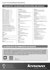
..., 7705, 7715, 7718, 7721, 7773, 7799 Serial ATA Hard Drive 160GB, 250GB, 320GB, 500GB, 1TB/7200rpm and 150GB/10k rpm Memory 512MB/1GB/2GB DDR2 667MHz/800MHz Optical Drive DVD-ROM, DVD Recordable, Blu-ray Recorder (Tower only) Integrated Communications Marvell 8057, 10M/100M...174; Office Professional 2007 60-Day Trial Version Microsoft® Windows Live™ Portal McAfee® VirusScan® Plus with Lenovo's energy-saving ThinkVision® monitors and keyboards provides a low energy consumption solution. 3 THINKCENTRE® A58 DESKTOP SPECIFICATIONS AND SERVICES Processor Intel...
..., 7705, 7715, 7718, 7721, 7773, 7799 Serial ATA Hard Drive 160GB, 250GB, 320GB, 500GB, 1TB/7200rpm and 150GB/10k rpm Memory 512MB/1GB/2GB DDR2 667MHz/800MHz Optical Drive DVD-ROM, DVD Recordable, Blu-ray Recorder (Tower only) Integrated Communications Marvell 8057, 10M/100M...174; Office Professional 2007 60-Day Trial Version Microsoft® Windows Live™ Portal McAfee® VirusScan® Plus with Lenovo's energy-saving ThinkVision® monitors and keyboards provides a low energy consumption solution. 3 THINKCENTRE® A58 DESKTOP SPECIFICATIONS AND SERVICES Processor Intel...
Brochure
Page 4
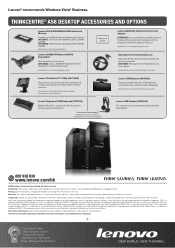
... 800MHz DDR2 SDRAM UDIMM (41U2978) 2GB PC2-6400 800MHz DDR2 SDRAM UDIMM www.lenovo.com/support/memory Lenovo 256MB ATI Radeon HD3470 DisplayPort Boost graphics performance (45K1636) Lenovo 256MB ATI Radeon HD3470 DisplayPort +VGA Graphics Card www.lenovo.com/support/graphiccards Image not shown Lenovo ADD2 DVI-D Monitor Connection Adapter (43R1985) Low-cost method to : www...
... 800MHz DDR2 SDRAM UDIMM (41U2978) 2GB PC2-6400 800MHz DDR2 SDRAM UDIMM www.lenovo.com/support/memory Lenovo 256MB ATI Radeon HD3470 DisplayPort Boost graphics performance (45K1636) Lenovo 256MB ATI Radeon HD3470 DisplayPort +VGA Graphics Card www.lenovo.com/support/graphiccards Image not shown Lenovo ADD2 DVI-D Monitor Connection Adapter (43R1985) Low-cost method to : www...
User Manual
Page 5
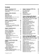
... Locating components 128 Locating parts on the system board 89 Removing and reinstalling the front bezel . . . . 89 Installing or replacing a memory module . . . . 90 Installing or replacing a PCI card 92 Replacing the battery 95 Replacing the power supply assembly . . ....discharge-sensitive devices . . 6 Grounding requirements 7 Safety notices (multi-lingual translations) . . . . . 7 Chapter 3. Diagnostics 45 Lenovo ThinkVantage Toolbox 45 Lenovo System Toolbox 45 PC-Doctor for Rescue and Recovery 46 PC-Doctor for DOS 46 Creating a diagnostic disc 46 Running the diagnostic program ...
... Locating components 128 Locating parts on the system board 89 Removing and reinstalling the front bezel . . . . 89 Installing or replacing a memory module . . . . 90 Installing or replacing a PCI card 92 Replacing the battery 95 Replacing the power supply assembly . . ....discharge-sensitive devices . . 6 Grounding requirements 7 Safety notices (multi-lingual translations) . . . . . 7 Chapter 3. Diagnostics 45 Lenovo ThinkVantage Toolbox 45 Lenovo System Toolbox 45 PC-Doctor for Rescue and Recovery 46 PC-Doctor for DOS 46 Creating a diagnostic disc 46 Running the diagnostic program ...
User Manual
Page 62
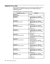
... board 56 Hardware Maintenance Manual See "Updating (flashing) BIOS from a disc" on page 278 2. System board 1. Flash the system. Run Setup 2. Flash the system. Run memory test 4. Flash the system. System board 1. See "Updating (flashing) BIOS from a disc" on page 278 3. System board 1. See "Updating (flashing) BIOS from a disc" on page...
... board 56 Hardware Maintenance Manual See "Updating (flashing) BIOS from a disc" on page 278 2. System board 1. Flash the system. Run Setup 2. Flash the system. Run memory test 4. Flash the system. System board 1. See "Updating (flashing) BIOS from a disc" on page 278 3. System board 1. See "Updating (flashing) BIOS from a disc" on page...

User Manual
Page 64
... threshold exceeded 001-197-XXX System test warning FRU/Action 1. Flash the system. See "Updating (flashing) BIOS from a disc" on page 278 2. System board 1. Run memory test 4. Flash the system. Run Setup 2. See "Updating (flashing) BIOS from a disc" on page 278 3. Flash the system. System board 1. System board Information only Re...
... threshold exceeded 001-197-XXX System test warning FRU/Action 1. Flash the system. See "Updating (flashing) BIOS from a disc" on page 278 2. System board 1. Run memory test 4. Flash the system. Run Setup 2. See "Updating (flashing) BIOS from a disc" on page 278 3. Flash the system. System board 1. System board Information only Re...

User Manual
Page 71
... re-test 2. Flash the system. System board System board 1. Flash the system and re-test. See "Updating (flashing) BIOS from a disc" on page 278 3. Run memory test 4. Re-start the test, if necessary 1. Re-run test 3.
... re-test 2. Flash the system. System board System board 1. Flash the system and re-test. See "Updating (flashing) BIOS from a disc" on page 278 3. Run memory test 4. Re-start the test, if necessary 1. Re-run test 3.

User Manual
Page 81
... Asset Security Test Passed 185-XXX-XXX Asset Security failure 185-278-XXX Asset Security Chassis Intrusion 201-000-XXX System Memory Test Passed 201-XXX-XXX System Memory error 202-000-XXX System Cache Test Passed 202-XXX-XXX System Cache error 206-000-XXX Diskette Drive Test Passed ...Enabled 2. If a component is called out by the test 2. System board 3. Check power supply voltages 3. Symptom-to "Undetermined problems" on page 81 2. Replace the memory module called out, make sure it is connected and/or enabled 2. See "Undetermined problems" on page 81 1. C2 Cover Switch 3.
... Asset Security Test Passed 185-XXX-XXX Asset Security failure 185-278-XXX Asset Security Chassis Intrusion 201-000-XXX System Memory Test Passed 201-XXX-XXX System Memory error 202-000-XXX System Cache Test Passed 202-XXX-XXX System Cache error 206-000-XXX Diskette Drive Test Passed ...Enabled 2. If a component is called out by the test 2. System board 3. Check power supply voltages 3. Symptom-to "Undetermined problems" on page 81 2. Replace the memory module called out, make sure it is connected and/or enabled 2. See "Undetermined problems" on page 81 1. C2 Cover Switch 3.

User Manual
Page 83
... program and press F7 to load defaults and then press F10 to -FRU index 77 Replace the system board. Perform a Boot-block recovery. Replace the memory module(s). 3. Replace the system board. Start the Setup Utility program and press F10 to Save and exit. 3. Replace the keyboard. 3. See Chapter ...or video adapter card error 1 long and 3 short beeps Keyboard error 1 long and 9 short beeps BIOS ROM error Continuos long beeps DRAM memory error FRU/Action Perform the following actions in order. 1. Diagnostic error code 415-XXX-XXX Modem error FRU/Action Remove the Modem and re-test...
... program and press F7 to load defaults and then press F10 to -FRU index 77 Replace the system board. Perform a Boot-block recovery. Replace the memory module(s). 3. Replace the system board. Start the Setup Utility program and press F10 to Save and exit. 3. Replace the keyboard. 3. See Chapter ...or video adapter card error 1 long and 3 short beeps Keyboard error 1 long and 9 short beeps BIOS ROM error Continuos long beeps DRAM memory error FRU/Action Perform the following actions in order. 1. Diagnostic error code 415-XXX-XXX Modem error FRU/Action Remove the Modem and re-test...
User Manual
Page 84
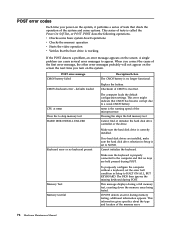
...checksum error - CPU at nnnn Press Esc to a weak CMOS battery. Make sure the hard disk drive is no longer functional. Memory Test: Memory test fail To purposely configure the computer without a keyboard, set to HALT ON ALL, BUT KEYBOARD. If POST detects an error during a...no keyboard present If no keys are installed, make sure the hard disk drive selection in Setup to NONE. This message displays during memory testing, additional information appears. Make sure the keyboard is incorrect. defaults loaded Replace the battery. The BIOS then ignores the missing keyboard ...
...checksum error - CPU at nnnn Press Esc to a weak CMOS battery. Make sure the hard disk drive is no longer functional. Memory Test: Memory test fail To purposely configure the computer without a keyboard, set to HALT ON ALL, BUT KEYBOARD. If POST detects an error during a...no keyboard present If no keys are installed, make sure the hard disk drive selection in Setup to NONE. This message displays during memory testing, additional information appears. Make sure the keyboard is incorrect. defaults loaded Replace the battery. The BIOS then ignores the missing keyboard ...
User Manual
Page 86
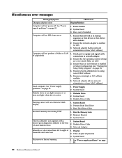
...are set to network adapter 2. Network adapter (advise network administrator of new MAC address) 1. System Board 3. Hard Disk Drive Cable 1. Memory Module 3. System Board 2. Video adapter (if present) 3. System Board 1. Flashing cursor with a known-good diagnostics diskette in Setup/Configuration...on LAN feature is enabled in the first 3.5-inch diskette drive. Ensure no interrupt or I/O address conflicts 6. System Board 2. Run the Memory tests 2. Network Adapter 1. See "Power supply problems" on page 51) 4. Network adapter (Advise network administrator of new MAC address)...
...are set to network adapter 2. Network adapter (advise network administrator of new MAC address) 1. System Board 3. Hard Disk Drive Cable 1. Memory Module 3. System Board 2. Video adapter (if present) 3. System Board 1. Flashing cursor with a known-good diagnostics diskette in Setup/Configuration...on LAN feature is enabled in the first 3.5-inch diskette drive. Ensure no interrupt or I/O address conflicts 6. System Board 2. Run the Memory tests 2. Network Adapter 1. See "Power supply problems" on page 51) 4. Network adapter (Advise network administrator of new MAC address)...

User Manual
Page 88
Extended video memory e. Diskette drive 3. Repeat steps 1 through 3 until you find the failing device or adapter. Memory modules d. Power-on the computer to re-test the system. 4. External Cache RAM g. Hard disk drive h. If all devices and adapters have been removed, and the problem continues, replace the system board. 82 Hardware Maintenance Manual External Cache f. c.
Extended video memory e. Diskette drive 3. Repeat steps 1 through 3 until you find the failing device or adapter. Memory modules d. Power-on the computer to re-test the system. 4. External Cache RAM g. Hard disk drive h. If all devices and adapters have been removed, and the problem continues, replace the system board. 82 Hardware Maintenance Manual External Cache f. c.

User Manual
Page 94
Locating components To remove the computer cover, see "Removing the computer cover" on page 86. Component locations 1 Heat sink and fan assembly 2 Memory modules 3 Battery 4 PCI Express x16 graphics card slot 5 PCI card 6 PCI card slot 7 PCI Express x1 card slot 8 Cover presence switch (Intrusion switch) (some models) 9 Rear fan assembly 10 Power supply assembly 88 Hardware Maintenance Manual Figure 4. Figure 4 shows the locations of the various components in your computer.
Locating components To remove the computer cover, see "Removing the computer cover" on page 86. Component locations 1 Heat sink and fan assembly 2 Memory modules 3 Battery 4 PCI Express x16 graphics card slot 5 PCI card 6 PCI card slot 7 PCI Express x1 card slot 8 Cover presence switch (Intrusion switch) (some models) 9 Rear fan assembly 10 Power supply assembly 88 Hardware Maintenance Manual Figure 4. Figure 4 shows the locations of the various components in your computer.

User Manual
Page 95
..., do the following: 1. See "Removing the computer cover" on the system board. Figure 5. Replacing FRUs - Tamdhu 89 System board parts locations 1 Microprocessor 2 Microprocessor fan connector 3 Memory slots (2) 4 Thermal sensor connector 5 Diskette drive connector 6 24-pin power connector 7 Battery 8 Cover presence (Intrusion) switch connector 9 SATA connectors (4) 10 Clear CMOS (Complementary Metal Oxide...
..., do the following: 1. See "Removing the computer cover" on the system board. Figure 5. Replacing FRUs - Tamdhu 89 System board parts locations 1 Microprocessor 2 Microprocessor fan connector 3 Memory slots (2) 4 Thermal sensor connector 5 Diskette drive connector 6 24-pin power connector 7 Battery 8 Cover presence (Intrusion) switch connector 9 SATA connectors (4) 10 Clear CMOS (Complementary Metal Oxide...
User Manual
Page 96
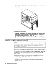
...into position on the right side of 4 GB. 90 Hardware Maintenance Manual Figure 6. To complete the installation, go to: http://www.lenovo.com/support This section provides instructions on how to a maximum of the ThinkCentre Safety and Warranty Guide, go to "Completing the FRU ... bezel with your computer or attempt any combination up to install or replace a memory module. Installing or replacing a memory module Attention Do not open your computer. v Use 512 MB, 1 GB, or 2 GB memory modules in any repair before reading and understanding the "Important safety information" in the...
...into position on the right side of 4 GB. 90 Hardware Maintenance Manual Figure 6. To complete the installation, go to: http://www.lenovo.com/support This section provides instructions on how to a maximum of the ThinkCentre Safety and Warranty Guide, go to "Completing the FRU ... bezel with your computer or attempt any combination up to install or replace a memory module. Installing or replacing a memory module Attention Do not open your computer. v Use 512 MB, 1 GB, or 2 GB memory modules in any repair before reading and understanding the "Important safety information" in the...

User Manual
Page 97
Replacing FRUs - Tamdhu 91 Remove any parts that might prevent access to the memory slots. 3. To install or replace a memory module, do the following: 1. See "Removing the computer cover" on page 89. 4. See "Locating parts on the system board" on page 86. 2. Figure... 7. Figure 8. Remove the computer cover. Opening the retaining clips If you are replacing an old memory module, open the retaining clips and remove the memory module being replaced as shown. Locate the memory slots. Note: Only DDR2 SDRAM DIMMs can be used. Open the retaining clips. Removing the...
Replacing FRUs - Tamdhu 91 Remove any parts that might prevent access to the memory slots. 3. To install or replace a memory module, do the following: 1. See "Removing the computer cover" on page 89. 4. See "Locating parts on the system board" on page 86. 2. Figure... 7. Figure 8. Remove the computer cover. Opening the retaining clips If you are replacing an old memory module, open the retaining clips and remove the memory module being replaced as shown. Locate the memory slots. Note: Only DDR2 SDRAM DIMMs can be used. Open the retaining clips. Removing the...

User Manual
Page 98
... over the memory slot. Installing the memory module What to do next: v To work with another piece of the ThinkCentre Safety and Warranty Guide, go to install or replace a PCI card. Make sure that came with the slot key 2 on how to : http://www.lenovo.com/support This section provides instructions on the...
... over the memory slot. Installing the memory module What to do next: v To work with another piece of the ThinkCentre Safety and Warranty Guide, go to install or replace a PCI card. Make sure that came with the slot key 2 on how to : http://www.lenovo.com/support This section provides instructions on the...

User Manual
Page 101
... PCI card What to the appropriate section. To obtain a copy of the ThinkCentre Safety and Warranty Guide, go to: http://www.lenovo.com/support Your computer has a special type of memory that came with another piece of hardware, go to secure the PCI cards. The battery normally requires no battery lasts forever...
... PCI card What to the appropriate section. To obtain a copy of the ThinkCentre Safety and Warranty Guide, go to: http://www.lenovo.com/support Your computer has a special type of memory that came with another piece of hardware, go to secure the PCI cards. The battery normally requires no battery lasts forever...

User Manual
Page 109
... repair before removing the computer cover. Carefully move the system board out of the ThinkCentre Safety and Warranty Guide, go to: http://www.lenovo.com/support This section provides instructions on how to replace the system board. To replace the system board, do next: v To work... in the ThinkCentre Safety and Warranty Guide that secure the system board to "Completing the FRU replacement" on page 92. 5. See "Installing or replacing a memory module" on page 90 and "Installing or replacing a PCI card" on page 120. See "Replacing the microprocessor" on page 105. 3. Chapter 8. Make...
... repair before removing the computer cover. Carefully move the system board out of the ThinkCentre Safety and Warranty Guide, go to: http://www.lenovo.com/support This section provides instructions on how to replace the system board. To replace the system board, do next: v To work... in the ThinkCentre Safety and Warranty Guide that secure the system board to "Completing the FRU replacement" on page 92. 5. See "Installing or replacing a memory module" on page 90 and "Installing or replacing a PCI card" on page 120. See "Replacing the microprocessor" on page 105. 3. Chapter 8. Make...

User Manual
Page 110
... another piece of the socket cover downward until the tabs 2 snap into position with the small handle. Installing the microprocessor socket cover 12. Reconnect all memory modules and adapter cards removed from the microprocessor socket, and then close the microprocessor retainer and lock it into position. Figure 19. Install the new...
... another piece of the socket cover downward until the tabs 2 snap into position with the small handle. Installing the microprocessor socket cover 12. Reconnect all memory modules and adapter cards removed from the microprocessor socket, and then close the microprocessor retainer and lock it into position. Figure 19. Install the new...

User Manual
Page 134
Figure 43 shows the location of the various components in your computer. Locating components To open the computer cover, see "Opening the computer cover" on page 126. Figure 43. Component locations 1 Hard disk drive 2 Heat sink and fan assembly 3 Internal speaker 4 Optical drive 5 Memory slots 6 Power supply assembly 128 Hardware Maintenance Manual
Figure 43 shows the location of the various components in your computer. Locating components To open the computer cover, see "Opening the computer cover" on page 126. Figure 43. Component locations 1 Hard disk drive 2 Heat sink and fan assembly 3 Internal speaker 4 Optical drive 5 Memory slots 6 Power supply assembly 128 Hardware Maintenance Manual


