Brochure
Page 2
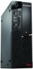
... Peace-of multiple read/write requests (such as Rescue and Recovery, Client Security Solution, System Update and Power Manager, are new onboard DirectX® 10 graphics providing an immersive highdefinition experience through clear video technology. On the graphics end of mind knowing that was built to transfer money. Lenovo® recommends Windows Vista® Business. Powered by other PC disasters.
... Peace-of multiple read/write requests (such as Rescue and Recovery, Client Security Solution, System Update and Power Manager, are new onboard DirectX® 10 graphics providing an immersive highdefinition experience through clear video technology. On the graphics end of mind knowing that was built to transfer money. Lenovo® recommends Windows Vista® Business. Powered by other PC disasters.
Brochure
Page 3
... 150GB/10k rpm Memory 512MB/1GB/2GB DDR2 667MHz/800MHz Optical Drive DVD-ROM, DVD Recordable, Blu-ray Recorder (Tower only) Integrated Communications Marvell 8057, 10M/100M/1000M Gigabit Ethernet Ports Tower/SFF: (8) USB 2.0 (2 Front/4 Rear/2 Internal), (2) PS/2, (2) Serial (1 standard, 1 optional), (1) Parallel, (2) Front audio ports: Headphone and Microphone, (3) Rear audio ports: Line in .) Keyboard Preferred Pro Full Size Keyboard (PS2), Preferred Pro Full Size Keyboard (USB), Preferred Pro USB Fingerprint Keyboard Graphic Card Integrated: Intel GMA...
... 150GB/10k rpm Memory 512MB/1GB/2GB DDR2 667MHz/800MHz Optical Drive DVD-ROM, DVD Recordable, Blu-ray Recorder (Tower only) Integrated Communications Marvell 8057, 10M/100M/1000M Gigabit Ethernet Ports Tower/SFF: (8) USB 2.0 (2 Front/4 Rear/2 Internal), (2) PS/2, (2) Serial (1 standard, 1 optional), (1) Parallel, (2) Front audio ports: Headphone and Microphone, (3) Rear audio ports: Line in .) Keyboard Preferred Pro Full Size Keyboard (PS2), Preferred Pro Full Size Keyboard (USB), Preferred Pro USB Fingerprint Keyboard Graphic Card Integrated: Intel GMA...
User Manual
Page 5
... board 129 Installing or replacing a memory module . . . . 130 Installing or replacing an adapter card . . . . . 132 Replacing the battery 134 Replacing the hard disk drive 136 Replacing the optical drive 137 Replacing the power supply assembly . . . . . 140 Replacing the heat sink and fan assembly . . . . 142 Replacing the microprocessor 144 Replacing the system board 147 Replacing the card reader 149 Replacing the front audio and USB assembly . . . 150 Replacing the internal speaker 151 iii Replacing FRUs (Machine types: 7522, 7560, 7610, and 7705.) . . 123 Locating connectors...
... board 129 Installing or replacing a memory module . . . . 130 Installing or replacing an adapter card . . . . . 132 Replacing the battery 134 Replacing the hard disk drive 136 Replacing the optical drive 137 Replacing the power supply assembly . . . . . 140 Replacing the heat sink and fan assembly . . . . 142 Replacing the microprocessor 144 Replacing the system board 147 Replacing the card reader 149 Replacing the front audio and USB assembly . . . 150 Replacing the internal speaker 151 iii Replacing FRUs (Machine types: 7522, 7560, 7610, and 7705.) . . 123 Locating connectors...
User Manual
Page 46
... on the Windows Vista operating system or the Windows XP operating system, click Start → All Programs → ThinkVantage → Access Help. After you have opened the Access Help information system, use the left panel to make a selection from the Contents tab or the Index tab, or use the Search tab to find the following information: v CRU installation or replacement instructions v Downloads and drivers v Publications v Parts information v Troubleshooting information v Links...
... on the Windows Vista operating system or the Windows XP operating system, click Start → All Programs → ThinkVantage → Access Help. After you have opened the Access Help information system, use the left panel to make a selection from the Contents tab or the Index tab, or use the Search tab to find the following information: v CRU installation or replacement instructions v Downloads and drivers v Publications v Parts information v Troubleshooting information v Links...
User Manual
Page 49
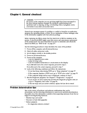
... tips Due to "Diagnostic error codes" on page 78. Power-on page 45. Run the Diagnostic programs. See Chapter 5, "Diagnostics," on the computer. For an explanation of these messages, refer to the information supplied with that the diagnostic program calls out or go to the variety of the problem: 1. v Machine type and model v Processor or hard disk upgrades v Failure symptom - If you receive an error, replace the part that software package. v If...
... tips Due to "Diagnostic error codes" on page 78. Power-on page 45. Run the Diagnostic programs. See Chapter 5, "Diagnostics," on the computer. For an explanation of these messages, refer to the information supplied with that the diagnostic program calls out or go to the variety of the problem: 1. v Machine type and model v Processor or hard disk upgrades v Failure symptom - If you receive an error, replace the part that software package. v If...

User Manual
Page 59
... devices connected to the SATA connectors (such as expected, do the following: 1. From the Setup Utility program menu, select Devices → ATA Drives Setup → SATA Controller. 3. To set the Floppy A, do one of the following to select the startup device of your computer. 2. Select the desired settings and press Enter. 4. Use the instructions in this section to start up from a device such as a hard disk drive or the disc in an optical drive as hard disk drives or the optical drive...
... devices connected to the SATA connectors (such as expected, do the following: 1. From the Setup Utility program menu, select Devices → ATA Drives Setup → SATA Controller. 3. To set the Floppy A, do one of the following to select the startup device of your computer. 2. Select the desired settings and press Enter. 4. Use the instructions in this section to start up from a device such as a hard disk drive or the disc in an optical drive as hard disk drives or the optical drive...
User Manual
Page 63
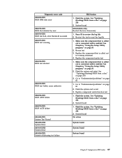
... "Undetermined problems" on page 278 2. Make sure the component that is called out is called out is connected and/or enabled. Replace the component under function test 1. Flash the system. Flash the system. See "Updating (flashing) BIOS from a disc" on page 278 3. Go to -FRU index 57 Re-run test 3. System board 1. System board No action System board System board System board Chapter 7. Diagnostic error code 000-039-XXX BIOS DMI data error 000...
... "Undetermined problems" on page 278 2. Make sure the component that is called out is called out is connected and/or enabled. Replace the component under function test 1. Flash the system. Flash the system. See "Updating (flashing) BIOS from a disc" on page 278 3. Go to -FRU index 57 Re-run test 3. System board 1. System board No action System board System board System board Chapter 7. Diagnostic error code 000-039-XXX BIOS DMI data error 000...
User Manual
Page 65
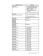
... "Updating (flashing) BIOS from a disc" on IRQ10 2. Flash the system and re-test 3. Replace component under function test System board System board System board 1. System board 1. System board 1. System board 1. Device on page 278 3. Device on IRQ7 2. System board 1. Device on IRQ1 2. See Chapter 6, "Using the Setup Utility program," on IRQ8 2. Diskette Cable 2. Device on page 51 2. If a component is called out, make sure it is connected and/or enabled. System board 1. Device on page 81 2. System board 1. System board...
... "Updating (flashing) BIOS from a disc" on IRQ10 2. Flash the system and re-test 3. Replace component under function test System board System board System board 1. System board 1. System board 1. System board 1. Device on page 278 3. Device on IRQ7 2. System board 1. Device on IRQ1 2. See Chapter 6, "Using the Setup Utility program," on IRQ8 2. Diskette Cable 2. Device on page 51 2. If a component is called out, make sure it is connected and/or enabled. System board 1. Device on page 81 2. System board 1. System board...

User Manual
Page 68
..., error threshold exceeded 1. Replace the component that is called out, make sure it is connected and/or enabled 2. Go to review the log file 2. Go to "Undetermined problems" on page 81 006-199-XXX 1. Remove external serial device, if present 2. Diskette drive Cable 2. Replace the component under test 006-198-XXX Diskette interface test aborted 1. See "Updating (flashing) BIOS from a disc" on page Diskette interface test failed, cause unknown 81 2. Video card, if installed...
..., error threshold exceeded 1. Replace the component that is called out, make sure it is connected and/or enabled 2. Go to review the log file 2. Go to "Undetermined problems" on page 81 006-199-XXX 1. Remove external serial device, if present 2. Diskette drive Cable 2. Replace the component under test 006-198-XXX Diskette interface test aborted 1. See "Updating (flashing) BIOS from a disc" on page Diskette interface test failed, cause unknown 81 2. Video card, if installed...

User Manual
Page 69
..., make sure it is called out is connected and/or enabled. Replace the component under function test 011-2XX-XXX Serial port signal failure 1. See Chapter 6, "Using the Setup Utility program," on page 81 2. Diagnostic error code FRU/Action 011-002-XXX 011-003-XXX Serial port Timeout/Parity error System board 011-013-XXX 011-014-XXX Serial port Control Signal/Loopback test failure System board 011-015-XXX Serial port External Loopback failure 1. Wrap plug 2. See "Updating (flashing) BIOS from a disc...
..., make sure it is called out is connected and/or enabled. Replace the component under function test 011-2XX-XXX Serial port signal failure 1. See Chapter 6, "Using the Setup Utility program," on page 81 2. Diagnostic error code FRU/Action 011-002-XXX 011-003-XXX Serial port Timeout/Parity error System board 011-013-XXX 011-014-XXX Serial port Control Signal/Loopback test failure System board 011-015-XXX Serial port External Loopback failure 1. Wrap plug 2. See "Updating (flashing) BIOS from a disc...

User Manual
Page 70
... board System board Information only Re-start the test to "Undetermined problems" on page 278 3. Make sure the component that is connected and/or enabled. See Chapter 6, "Using the Setup Utility program," on page 278 3. If a component is called out in warning statement 4. Replace component under test 1. Flash the system and re-test. See "Updating (flashing) BIOS from a disc" on page 51 2. External parallel device 2. Flash the system and re-test. System board 64 Hardware Maintenance Manual Diagnostic error code...
... board System board Information only Re-start the test to "Undetermined problems" on page 278 3. Make sure the component that is connected and/or enabled. See Chapter 6, "Using the Setup Utility program," on page 278 3. If a component is called out in warning statement 4. Replace component under test 1. Flash the system and re-test. See "Updating (flashing) BIOS from a disc" on page 51 2. External parallel device 2. Flash the system and re-test. System board 64 Hardware Maintenance Manual Diagnostic error code...

User Manual
Page 71
Remove USB device(s) and re-test 2. Reboot the system 2. System board System board 1. Flash the system. Make sure the component that is called out is called out in warning statement 4. Re-run test 3. System board 1. Flash the system. Diagnostic error code 015-000-XXX USB (Universal Serial Bus) port Interface Test Passed 015-001-XXX USB port Presence 015-002-XXX USB port Timeout 015-015-XXX USB port External Loopback failure 015-027-XXX USB port Configuration/Setup error 015-032-XXX USB port Device Controller failure 015...
Remove USB device(s) and re-test 2. Reboot the system 2. System board System board 1. Flash the system. Make sure the component that is called out is called out in warning statement 4. Re-run test 3. System board 1. Flash the system. Diagnostic error code 015-000-XXX USB (Universal Serial Bus) port Interface Test Passed 015-001-XXX USB port Presence 015-002-XXX USB port Timeout 015-015-XXX USB port External Loopback failure 015-027-XXX USB port Configuration/Setup error 015-032-XXX USB port Device Controller failure 015...
User Manual
Page 84
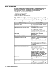
... options. POST error message CMOS battery failed Description/Action The CMOS battery is no keys are installed, make sure the hard disk drive selection in Setup is set the error halt condition in Setup to the computer and that no longer functional. nnnn is called the Power-On Self-Test, or POST. Cannot initialize the keyboard. POST error codes Each time you turn on the screen. This series of tests is the running speed of the memory error. 78 Hardware Maintenance Manual...
... options. POST error message CMOS battery failed Description/Action The CMOS battery is no keys are installed, make sure the hard disk drive selection in Setup is set the error halt condition in Setup to the computer and that no longer functional. nnnn is called the Power-On Self-Test, or POST. Cannot initialize the keyboard. POST error codes Each time you turn on the screen. This series of tests is the running speed of the memory error. 78 Hardware Maintenance Manual...
User Manual
Page 86
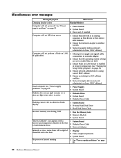
... operating system settings are set to network adapter 2. Ensure Wake on LAN feature is active. Display 2. Diskette drive in Setup/Configuration (see "Starting the Setup Utility program" on page 55. Intensity or color varies from server Computer will not power-off. Ensure that network is in the first 3.5-inch diskette drive. System Board 3. System Board 2. Check power supply and signal cable connections to enable Wake on or does not light when drive is enabled in -use light remains on LAN 3. Hard Disk Drive Cable 1. System Board 1. Run the Memory tests...
... operating system settings are set to network adapter 2. Ensure Wake on LAN feature is active. Display 2. Diskette drive in Setup/Configuration (see "Starting the Setup Utility program" on page 55. Intensity or color varies from server Computer will not power-off. Ensure that network is in the first 3.5-inch diskette drive. System Board 3. System Board 2. Check power supply and signal cable connections to enable Wake on or does not light when drive is enabled in -use light remains on LAN 3. Hard Disk Drive Cable 1. System Board 1. Run the Memory tests...
User Manual
Page 87
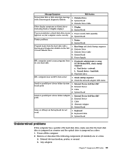
...Check the network adapter LED status Serial or parallel port device failure (system board port) 1. System Board Serial or parallel port device failure (adapter port) 1. Message/Symptom FRU/Action Non-system disk or disk error-type message with a known-good diagnostics diskette in -use 1. Diskette Drive Cable 4. External Device 3. Keyboard Cable 3. Power switch/LED assembly light not on the keyboard do not work 1. Power Supply RPL computer cannot access programs from server 1. Second device - Cable 4. External Device Self-Test OK? 2. System Board Some...
...Check the network adapter LED status Serial or parallel port device failure (system board port) 1. System Board Serial or parallel port device failure (adapter port) 1. Message/Symptom FRU/Action Non-system disk or disk error-type message with a known-good diagnostics diskette in -use 1. Diskette Drive Cable 4. External Device 3. Keyboard Cable 3. Power switch/LED assembly light not on the keyboard do not work 1. Power Supply RPL computer cannot access programs from server 1. Second device - Cable 4. External Device Self-Test OK? 2. System Board Some...
User Manual
Page 96
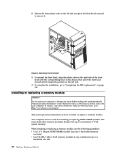
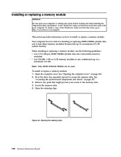
... installation, go to: http://www.lenovo.com/support This section provides instructions on how to "Completing the FRU replacement" on page 120. To obtain a copy of the ThinkCentre Safety and Warranty Guide, go to install or replace a memory module. When installing or replacing a memory module, use the following guidelines: v Use 1.8 V, 240-pin, DDR2 DIMMs (double data rate 2 dual inline memory modules). Your computer has two slots for installing or replacing...
... installation, go to: http://www.lenovo.com/support This section provides instructions on how to "Completing the FRU replacement" on page 120. To obtain a copy of the ThinkCentre Safety and Warranty Guide, go to install or replace a memory module. When installing or replacing a memory module, use the following guidelines: v Use 1.8 V, 240-pin, DDR2 DIMMs (double data rate 2 dual inline memory modules). Your computer has two slots for installing or replacing...
User Manual
Page 136
....lenovo.com/support This section provides instructions on how to access the memory slots. Opening the retaining clips 130 Hardware Maintenance Manual To obtain a copy of 4 GB system memory. v Use 512 MB, 1 GB, or 2 GB memory modules in the ThinkCentre Safety and Warranty Guide that might prevent your computer. To install or replace a memory module: 1. When installing or replacing a memory module, use the following guidelines: v Use 1.8 V, 240-pin, DDR2 DIMMs (double data rate 2 dual...
....lenovo.com/support This section provides instructions on how to access the memory slots. Opening the retaining clips 130 Hardware Maintenance Manual To obtain a copy of 4 GB system memory. v Use 512 MB, 1 GB, or 2 GB memory modules in the ThinkCentre Safety and Warranty Guide that might prevent your computer. To install or replace a memory module: 1. When installing or replacing a memory module, use the following guidelines: v Use 1.8 V, 240-pin, DDR2 DIMMs (double data rate 2 dual...

User Manual
Page 284
..., remove the disc from the drives and turn off your machine type and click Go. b. Click the BIOS update link. 3. Remove all the BIOS related links. c. Follow the printed instructions to easily locate all media from the optical drive. Follow the instructions on the screen to http://www.lenovo.com/support. 2. Updating (flashing) BIOS from a POST/BIOS update failure If the power to your computer is interrupted while POST/BIOS is very important because these instructions. d. Type in the machine type/model...
..., remove the disc from the drives and turn off your machine type and click Go. b. Click the BIOS update link. 3. Remove all the BIOS related links. c. Follow the printed instructions to easily locate all media from the optical drive. Follow the instructions on the screen to http://www.lenovo.com/support. 2. Updating (flashing) BIOS from a POST/BIOS update failure If the power to your computer is interrupted while POST/BIOS is very important because these instructions. d. Type in the machine type/model...
User Manual
Page 289
..., hard disk drive 55 Boot-block Recovery 278 C cables, routing 155 card reader, replacing 112, 149 changing startup device sequence 54 components, accessing system board 127 components, internal 88, 128 computer cover opening 126 removing 86 computer cover, reinstalling 120 connectors front 84, 124 rear 85, 125 considerations, password 52 D diagnostics 45 diskette drive, replacing 112 E electrical safety 3 electrostatic discharge-sensitive devices 6 environment, operating 41 error codes, diagnostic 56 error codes, POST 78 exiting, Setup Utility program 54 F failure, recovering from POST/BIOS...
..., hard disk drive 55 Boot-block Recovery 278 C cables, routing 155 card reader, replacing 112, 149 changing startup device sequence 54 components, accessing system board 127 components, internal 88, 128 computer cover opening 126 removing 86 computer cover, reinstalling 120 connectors front 84, 124 rear 85, 125 considerations, password 52 D diagnostics 45 diskette drive, replacing 112 E electrical safety 3 electrostatic discharge-sensitive devices 6 environment, operating 41 error codes, diagnostic 56 error codes, POST 78 exiting, Setup Utility program 54 F failure, recovering from POST/BIOS...

User Manual
Page 290
... a POST/BIOS update failure 278 recovery Boot-block Recovery 278 removing computer cover 86 replacing battery 95, 134 card reader 112, 149 diskette drive 112 front audio and USB assembly 119, 150 front fan assembly 113 hard disk drive 105, 136 heat sink and fan assembly 98, 142 internal speaker 117, 151 microprocessor 100, 144 optical drive 110, 137 PCI card 92 power supply assembly 96, 140 rear fan assembly 115 system board 103, 147 RoHS 2 S safety information 3 safety inspection guide 5 safety...
... a POST/BIOS update failure 278 recovery Boot-block Recovery 278 removing computer cover 86 replacing battery 95, 134 card reader 112, 149 diskette drive 112 front audio and USB assembly 119, 150 front fan assembly 113 hard disk drive 105, 136 heat sink and fan assembly 98, 142 internal speaker 117, 151 microprocessor 100, 144 optical drive 110, 137 PCI card 92 power supply assembly 96, 140 rear fan assembly 115 system board 103, 147 RoHS 2 S safety information 3 safety inspection guide 5 safety...


