
Service Manual
Page 1
Website:http://biz.LGservice.com E-mail:http://www.LGEservice.com/techsup.html COLOR MONITOR SERVICE MANUAL CHASSIS NO. : CA-119 FACTORY MODEL: T710BH MODEL: T710B (T710BH-EL) T710BH (T710BH-HL) T710SH (T710BH-SL) *( ) ID LABEL Model No. CAUTION BEFORE SERVICING THE UNIT, READ THE SAFETY PRECAUTIONS IN THIS MANUAL. MENU SELECT Brightview
Website:http://biz.LGservice.com E-mail:http://www.LGEservice.com/techsup.html COLOR MONITOR SERVICE MANUAL CHASSIS NO. : CA-119 FACTORY MODEL: T710BH MODEL: T710B (T710BH-EL) T710BH (T710BH-HL) T710SH (T710BH-SL) *( ) ID LABEL Model No. CAUTION BEFORE SERVICING THE UNIT, READ THE SAFETY PRECAUTIONS IN THIS MANUAL. MENU SELECT Brightview
Service Manual
Page 3
... to prevent X-radiation, shock, fire, or other hazards. Be sure to remove all of the high voltage used in this color monitor because of the following steps describe how to measure the high voltage and how to avoid damage and scratching during service operation. The basic... joints, frayed leads, damaged insulation, solder splashes, or the sharp points. The high voltage meter should be taken while servicing this color monitor which have been overheated as the associated flyback and yoke circuits. It is keep the high voltage at the factory recommended level. •...
... to prevent X-radiation, shock, fire, or other hazards. Be sure to remove all of the high voltage used in this color monitor because of the following steps describe how to measure the high voltage and how to avoid damage and scratching during service operation. The basic... joints, frayed leads, damaged insulation, solder splashes, or the sharp points. The high voltage meter should be taken while servicing this color monitor which have been overheated as the associated flyback and yoke circuits. It is keep the high voltage at the factory recommended level. •...
Service Manual
Page 5
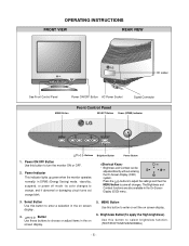
... this button to enter a selection in the on screen display. 5. stand-by, suspend, or power off mode - Select Button Use this button to turn the monitor ON or OFF. 2. Button Use these buttons to save all changes. Brightview Button(To apply the High brightness) Use this button to enter or exit...
... this button to enter a selection in the on screen display. 5. stand-by, suspend, or power off mode - Select Button Use this button to turn the monitor ON or OFF. 2. Button Use these buttons to save all changes. Brightview Button(To apply the High brightness) Use this button to enter or exit...
Service Manual
Page 7
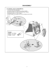
TILT/SWIVEL & BACK COVER REMOVAL 1) Set the monitor face downward. 2) Carefully remove the Tilt/Swivel by pulling it upward. 3) Pressing the latch (b), Back cover by pushing it upward. 4) Release the latch (c). (See Tip Spec.) 5) Slide the Back Cover away from the Front Cabinet of the monitor. Back Cover (c) Cabinet (a) Tip Spec. DISASSEMBLY 1. A(Width) : 5.0~15.0mm B(Depth) : 0.6~0.9mm C(Height) : 12.0mm C Tip AB (b) 1 3 3 2 2 -7-
TILT/SWIVEL & BACK COVER REMOVAL 1) Set the monitor face downward. 2) Carefully remove the Tilt/Swivel by pulling it upward. 3) Pressing the latch (b), Back cover by pushing it upward. 4) Release the latch (c). (See Tip Spec.) 5) Slide the Back Cover away from the Front Cabinet of the monitor. Back Cover (c) Cabinet (a) Tip Spec. DISASSEMBLY 1. A(Width) : 5.0~15.0mm B(Depth) : 0.6~0.9mm C(Height) : 12.0mm C Tip AB (b) 1 3 3 2 2 -7-
Service Manual
Page 9
... vertical pulse by degaussing the shadow mask in the CRT during turning on center and corners in this circuit prevents interference between the monitor and other circuit. (horizontal and vertical deflection, video amplifier, ...etc.) 4. This circuit makes the horizontal deflection by increasing DC ...voltage output circuit is supplied to the vertical deflection yoke. 13. This circuit eliminates abnormal color of power input line flowing into the monitor and/or some noise generated in the screen. 14. Micom(Microprocessor) Circuit. Line Filter & Associated Circuit. This is used for...
... vertical pulse by degaussing the shadow mask in the CRT during turning on center and corners in this circuit prevents interference between the monitor and other circuit. (horizontal and vertical deflection, video amplifier, ...etc.) 4. This circuit makes the horizontal deflection by increasing DC ...voltage output circuit is supplied to the vertical deflection yoke. 13. This circuit eliminates abnormal color of power input line flowing into the monitor and/or some noise generated in the screen. 14. Micom(Microprocessor) Circuit. Line Filter & Associated Circuit. This is used for...
Service Manual
Page 11
.... 8) DIST. IBM compatible PC. - Alignment Adaptor and Software. - White Balance Meter. - ADJ. → FOS. Do not run the alignment program on the monitor. Adjustment should be the best condition. 18) Save of the Mode 1. 19) PRESET EXIT → Y (Yes) command. ADJ. → BALANCE command. 9)...the alignment program. - 11 - Install the cable for adjustment such as arrow keys to 150(96) at Mode 1. 2) Run alignment program for T710BH on the White Balance Meter with saved each mode data. - ADJ. → CTRL PWM → TILT command. 7) Adjust tilt as Figure...
.... 8) DIST. IBM compatible PC. - Alignment Adaptor and Software. - White Balance Meter. - ADJ. → FOS. Do not run the alignment program on the monitor. Adjustment should be the best condition. 18) Save of the Mode 1. 19) PRESET EXIT → Y (Yes) command. ADJ. → BALANCE command. 9)...the alignment program. - 11 - Install the cable for adjustment such as arrow keys to 150(96) at Mode 1. 2) Run alignment program for T710BH on the White Balance Meter with saved each mode data. - ADJ. → CTRL PWM → TILT command. 7) Adjust tilt as Figure...
Service Manual
Page 12
Adjustment for Focus. 1) Set the Brightness and Contrast to 32±1FL of monitor. 3) Exit from the program. 4. message of the luminance. 23) After push the "ENTER" key, and "COMMAND → PRESET EXIT → Y(Yes)" command. 24) Exit from ...
Adjustment for Focus. 1) Set the Brightness and Contrast to 32±1FL of monitor. 3) Exit from the program. 4. message of the luminance. 23) After push the "ENTER" key, and "COMMAND → PRESET EXIT → Y(Yes)" command. 24) Exit from ...
Service Manual
Page 30
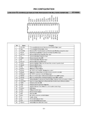
- 30 - H/HVSyn 1 VSyn 2 HLckVBk 3 HOscF 4 HPLL2C 5 CO 6 HGND 7 RO 8 HPLL1F 9 HPosF 10 HMoirØ 11 HFly 12 RefOut 13 BComp 14 BRegIn 15 BISense 16 32 VDyCor 31 SDA 30 SCL 29 Vcc 28 BOut 27 GND 26 HOut 25 XRay 24 EWOut 23 VOut 22 VCap 21 VGND 20 VAGCCap 19 VOscF 18 VEHTIn 17 HEHTIn STV6888 PIN CONFIGURATION LOW-COST I2C CONTROLLED DEFLECTION PROCESSOR FOR MULTISYNC MONITORS
- 30 - H/HVSyn 1 VSyn 2 HLckVBk 3 HOscF 4 HPLL2C 5 CO 6 HGND 7 RO 8 HPLL1F 9 HPosF 10 HMoirØ 11 HFly 12 RefOut 13 BComp 14 BRegIn 15 BISense 16 32 VDyCor 31 SDA 30 SCL 29 Vcc 28 BOut 27 GND 26 HOut 25 XRay 24 EWOut 23 VOut 22 VCap 21 VGND 20 VAGCCap 19 VOscF 18 VEHTIn 17 HEHTIn STV6888 PIN CONFIGURATION LOW-COST I2C CONTROLLED DEFLECTION PROCESSOR FOR MULTISYNC MONITORS


