
Service Manual
Page 2
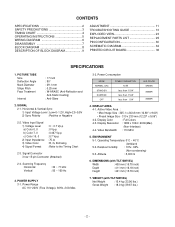
... INSTRUCTIONS 5 WIRING DIAGRAM 6 DISASSEMBLY 7 BLOCK DIAGRAM 8 DESCRIPTION OF BLOCK DIAGRAM 9 ADJUSTMENT 11 TROUBLESHOOTING GUIDE 13 EXPLODED VIEW 23 REPLACEMENT PARTS LIST 25 PIN CONFIGURATION 30 SCHEMATIC DIAGRAM 34 PRINTED CIRCUIT BOARD 36 SPECIFICATIONS 1. WEIGHT (with TILT/SWIVEL) Width : 400 mm (15.75 inch) Depth : 411 mm (16.18 inch) Height : 401...
... INSTRUCTIONS 5 WIRING DIAGRAM 6 DISASSEMBLY 7 BLOCK DIAGRAM 8 DESCRIPTION OF BLOCK DIAGRAM 9 ADJUSTMENT 11 TROUBLESHOOTING GUIDE 13 EXPLODED VIEW 23 REPLACEMENT PARTS LIST 25 PIN CONFIGURATION 30 SCHEMATIC DIAGRAM 34 PRINTED CIRCUIT BOARD 36 SPECIFICATIONS 1. WEIGHT (with TILT/SWIVEL) Width : 400 mm (15.75 inch) Depth : 411 mm (16.18 inch) Height : 401...
Service Manual
Page 3
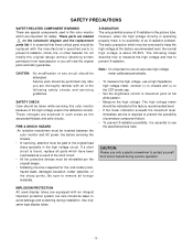
... integral implosion protection system, but care should be exercised is about 25.5KV. Use only same type display tubes. -3- These voltages are marked on the schematic diagram and the replacement parts list. There are special components used in such areas as a result of the following steps describe how to measure the...
... integral implosion protection system, but care should be exercised is about 25.5KV. Use only same type display tubes. -3- These voltages are marked on the schematic diagram and the replacement parts list. There are special components used in such areas as a result of the following steps describe how to measure the...