
Service Manual
Page 2
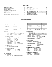
... INSTRUCTIONS 5 WIRING DIAGRAM 6 DISASSEMBLY 7 BLOCK DIAGRAM 8 DESCRIPTION OF BLOCK DIAGRAM 9 ADJUSTMENT 11 TROUBLESHOOTING GUIDE 13 EXPLODED VIEW 23 REPLACEMENT PARTS LIST 25 PIN CONFIGURATION 30 SCHEMATIC DIAGRAM 34 PRINTED CIRCUIT BOARD 36 SPECIFICATIONS 1. Scanning Frequency Horizontal Vertical : 30 ~ 71 kHz : 50 ~ 160 Hz 3. SIGNAL 2-1.
... INSTRUCTIONS 5 WIRING DIAGRAM 6 DISASSEMBLY 7 BLOCK DIAGRAM 8 DESCRIPTION OF BLOCK DIAGRAM 9 ADJUSTMENT 11 TROUBLESHOOTING GUIDE 13 EXPLODED VIEW 23 REPLACEMENT PARTS LIST 25 PIN CONFIGURATION 30 SCHEMATIC DIAGRAM 34 PRINTED CIRCUIT BOARD 36 SPECIFICATIONS 1. Scanning Frequency Horizontal Vertical : 30 ~ 71 kHz : 50 ~ 160 Hz 3. SIGNAL 2-1.
Service Manual
Page 3
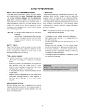
... from manufacturer or you are equipped with an integral implosion protection system, but care should be inspected for safety. These voltages are marked on the schematic diagram and the replacement parts list. the normal high voltage is the picture tube. The high voltage meter should be paid to prevent X-radiation, shock...
... from manufacturer or you are equipped with an integral implosion protection system, but care should be inspected for safety. These voltages are marked on the schematic diagram and the replacement parts list. the normal high voltage is the picture tube. The high voltage meter should be paid to prevent X-radiation, shock...