
Service Manual
Page 3
... exceeds the maximum level, immediate service is required to use a high impedance high voltage meter, connect (-) to chassis and (+) to the CDT anode cap. • Set the brightness control to protect yourself from manufacturer or you are marked on the schematic diagram and the replacement parts list. There are exposed in...
... exceeds the maximum level, immediate service is required to use a high impedance high voltage meter, connect (-) to chassis and (+) to the CDT anode cap. • Set the brightness control to protect yourself from manufacturer or you are marked on the schematic diagram and the replacement parts list. There are exposed in...
Service Manual
Page 5
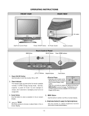
... color changes to enter a selection in the on screen display. 6. Select Button Use this button to save all changes. Press the buttons to adjust the settings and then the MENU button to enter or exit the on screen display. 5. MENU Button Use this button to orange, and if abnormal or damaging...
... color changes to enter a selection in the on screen display. 6. Select Button Use this button to save all changes. Press the buttons to adjust the settings and then the MENU button to enter or exit the on screen display. 5. MENU Button Use this button to orange, and if abnormal or damaging...
Service Manual
Page 7
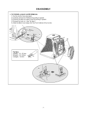
A(Width) : 5.0~15.0mm B(Depth) : 0.6~0.9mm C(Height) : 12.0mm C Tip AB (b) 1 3 3 2 2 -7- Back Cover (c) Cabinet (a) Tip Spec. DISASSEMBLY 1. TILT/SWIVEL & BACK COVER REMOVAL 1) Set the monitor face downward. 2) Carefully remove the Tilt/Swivel by pulling it upward. 3) Pressing the latch (b), Back cover by pushing it upward. 4) Release the latch (c). (See Tip Spec.) 5) Slide the Back Cover away from the Front Cabinet of the monitor.
A(Width) : 5.0~15.0mm B(Depth) : 0.6~0.9mm C(Height) : 12.0mm C Tip AB (b) 1 3 3 2 2 -7- Back Cover (c) Cabinet (a) Tip Spec. DISASSEMBLY 1. TILT/SWIVEL & BACK COVER REMOVAL 1) Set the monitor face downward. 2) Carefully remove the Tilt/Swivel by pulling it upward. 3) Pressing the latch (b), Back cover by pushing it upward. 4) Release the latch (c). (See Tip Spec.) 5) Slide the Back Cover away from the Front Cabinet of the monitor.
Service Manual
Page 9
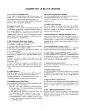
... of the transformer(T901). 5) These secondary voltages are rectified by increasing DC 50V which is applied to the primary coil of H and V sync. 3) The Micom sets operating mode and offers the controlled data. (H-size, H-position, V-size, ... Dynamic Focus Output Circuit. This circuit eliminates abnormal color of the screen by supplying the...
... of the transformer(T901). 5) These secondary voltages are rectified by increasing DC 50V which is applied to the primary coil of H and V sync. 3) The Micom sets operating mode and offers the controlled data. (H-size, H-position, V-size, ... Dynamic Focus Output Circuit. This circuit eliminates abnormal color of the screen by supplying the...
Service Manual
Page 11
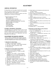
... in EEPROM (mode data and color data) will be erased. 4) Power button of CDT magnetized, then press DEGAUSS on the OSD menu. Set external Brightness and Contrast volume to 127(2F) position. ADJ. → BALANCE command. 9) Adjust parallelogram as arrow keys to 150(96) ...13) DRIVE ADJ.→ No 1. command. 14) Set Brightness and Contrast to Max position. 15) Set SUB-CONTRAST 200(C8) (decimal) position. 16) Set B-DRIVE to be the best condition. 8) DIST. Digital Voltmeter. - White Balance Meter. - Luminance Meter. - Adjustment for T710BH on the monitor. ADJ. → CTRL PWM ...
... in EEPROM (mode data and color data) will be erased. 4) Power button of CDT magnetized, then press DEGAUSS on the OSD menu. Set external Brightness and Contrast volume to 127(2F) position. ADJ. → BALANCE command. 9) Adjust parallelogram as arrow keys to 150(96) ...13) DRIVE ADJ.→ No 1. command. 14) Set Brightness and Contrast to Max position. 15) Set SUB-CONTRAST 200(C8) (decimal) position. 16) Set B-DRIVE to be the best condition. 8) DIST. Digital Voltmeter. - White Balance Meter. - Luminance Meter. - Adjustment for T710BH on the monitor. ADJ. → CTRL PWM ...
Service Manual
Page 12
... on the FBT that focus should be the best condition. - 12 - Input EDID Data. 1) Display color 15,0 cross hatch pattern at Mode 4. 20) Set Brightness and Contrast to Max position. 21) COLOR ADJ. → LUMINANCE → ABL command. 22) Adjust ABL to max position. 2) Display H character ...EEPROM → Write EDID command and confirm "EDID Write OK!!" message of monitor. 3) Exit from the alignment program. 4) Power switch OFF/ON for Focus. 1) Set the Brightness and Contrast to 32±1FL of the luminance. 23) After push the "ENTER" key, and "COMMAND → PRESET EXIT → Y(Yes)"...
... on the FBT that focus should be the best condition. - 12 - Input EDID Data. 1) Display color 15,0 cross hatch pattern at Mode 4. 20) Set Brightness and Contrast to Max position. 21) COLOR ADJ. → LUMINANCE → ABL command. 22) Adjust ABL to max position. 2) Display H character ...EEPROM → Write EDID command and confirm "EDID Write OK!!" message of monitor. 3) Exit from the alignment program. 4) Power switch OFF/ON for Focus. 1) Set the Brightness and Contrast to 32±1FL of the luminance. 23) After push the "ENTER" key, and "COMMAND → PRESET EXIT → Y(Yes)"...


