

User Guide
Page 8
... In OUT A 2 1 2 OUT 1 2 AUDIO 1 2 AUDIO D-SUB D-SUB PR PR P B COMPONENT P B COMPONENT Y Y D-SUB DC-OUT HDMI/DVI DC-OUT HDMI/DVI PR P B COMPONENT Y DC-OUT HDMI/DVI 3 Audio DC-In Cable DC-OUT Notice Be cautious to avoid your hand being caught between the speaker and Stand...its lowest height, with the speaker fully equipped. 4. Connect the audio cable to the appropriate female socket of the monitor. When using HDMI, you hear the clicking sound. 3. Connecting the speakers - L246WPM Connecting the speaker 1. Insert the projecting hook of the speaker in the...
... In OUT A 2 1 2 OUT 1 2 AUDIO 1 2 AUDIO D-SUB D-SUB PR PR P B COMPONENT P B COMPONENT Y Y D-SUB DC-OUT HDMI/DVI DC-OUT HDMI/DVI PR P B COMPONENT Y DC-OUT HDMI/DVI 3 Audio DC-In Cable DC-OUT Notice Be cautious to avoid your hand being caught between the speaker and Stand...its lowest height, with the speaker fully equipped. 4. Connect the audio cable to the appropriate female socket of the monitor. When using HDMI, you hear the clicking sound. 3. Connecting the speakers - L246WPM Connecting the speaker 1. Insert the projecting hook of the speaker in the...
User Guide
Page 9
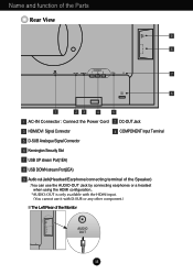
Name and function of the Parts Rear View 9 8 OUT AUDIO 2 1 COMPONENT AC-IN DC-OUT HDMI/DVI Y PB PR D-SUB 7 6 1 23 4 5 1 AC-IN Connector : Connect the Power Cord 2 DC-OUT Jack 3 HDMI/DVI Signal Connector 4 COMPONENT Input Terminal 5 D-SUB Analogue Signal Connector 6 Kensington Security Slot 7 USB UP ...terminal of the Speaker) : You can use the AUDIO-OUT Jack by connecting earphones or a headset when using the HDMI configuration.. *AUDIO-OUT is only available with the HDMI input. (You cannot use it with D-SUB or any other component.) The Left Rear of the Monitor OUT AUDIO...
Name and function of the Parts Rear View 9 8 OUT AUDIO 2 1 COMPONENT AC-IN DC-OUT HDMI/DVI Y PB PR D-SUB 7 6 1 23 4 5 1 AC-IN Connector : Connect the Power Cord 2 DC-OUT Jack 3 HDMI/DVI Signal Connector 4 COMPONENT Input Terminal 5 D-SUB Analogue Signal Connector 6 Kensington Security Slot 7 USB UP ...terminal of the Speaker) : You can use the AUDIO-OUT Jack by connecting earphones or a headset when using the HDMI configuration.. *AUDIO-OUT is only available with the HDMI input. (You cannot use it with D-SUB or any other component.) The Left Rear of the Monitor OUT AUDIO...
User Guide
Page 10
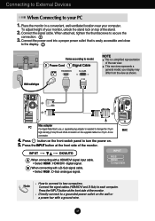
...For Apple Macintosh use, a separate plug adapter is easily accessible and close to the display. 2 Varies according to model. Connect the signal cables (HDMI/DVI and D-Sub) to secure the 3. Connect the 1 power cord into a proper power outlet that is needed to change the 15 pin high...the INPUT button at the front side of your display may differ from the view as shown. B When connecting with a HDMI/DVI signal input cable. • Select HDMI : HDMI/DVI digital signal. Connect the signal cable. your monitor, unlock the stand lock on the wall or a power bar with ...
...For Apple Macintosh use, a separate plug adapter is easily accessible and close to the display. 2 Varies according to model. Connect the signal cables (HDMI/DVI and D-Sub) to secure the 3. Connect the 1 power cord into a proper power outlet that is needed to change the 15 pin high...the INPUT button at the front side of your display may differ from the view as shown. B When connecting with a HDMI/DVI signal input cable. • Select HDMI : HDMI/DVI digital signal. Connect the signal cable. your monitor, unlock the stand lock on the wall or a power bar with ...

User Guide
Page 11
... connecting with a Component cable. • Select Component. Press the INPUT button at the front side of the same color. 2. Speaker AUDIO IN DC-OUT HDMI/DVI COMPONENT Y PB PR D-SUB 1 2 AUDIO OUT PB PR PB PR Monitor RCA-Stereo cable (not included) Component Cable (not included) DVD/VIDEO.../HDTV PB PR PB PR DVD/VIDEO/HDTV 3. INPUT OK/AUTO A When connecting with a Component cable 1. Connect the power cord. INPUT RGB HDMI Component A10 Connect the Component cables and RCA to the sockets of the monitor. Connect the terminals to Stereo cables properly.
... connecting with a Component cable. • Select Component. Press the INPUT button at the front side of the same color. 2. Speaker AUDIO IN DC-OUT HDMI/DVI COMPONENT Y PB PR D-SUB 1 2 AUDIO OUT PB PR PB PR Monitor RCA-Stereo cable (not included) Component Cable (not included) DVD/VIDEO.../HDTV PB PR PB PR DVD/VIDEO/HDTV 3. INPUT OK/AUTO A When connecting with a Component cable 1. Connect the power cord. INPUT RGB HDMI Component A10 Connect the Component cables and RCA to the sockets of the monitor. Connect the terminals to Stereo cables properly.
User Guide
Page 12
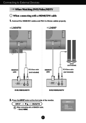
... DVD/Video/HDTV When connecting with a HDMI/DVI cable. • Select HDMI. INPUT OK/AUTO A When connecting with a HDMI/DVI cable 1. Press the INPUT button at the front side of the monitor. L246WPM L246WP OUT AUDIO OUT AUDIO 2 2 1 1 COMPONENT DC-OUT HDMI/DVI Y PB PR D-SUB AUDIO IN... COMPONENT DC-OUT HDMI/DVI Y PB PR D-SUB HDMI/DVI cable RCA-Stereo cable (not included) HDMI/DVI cable Speaker (not included) RCA-Stereo cable (not...
... DVD/Video/HDTV When connecting with a HDMI/DVI cable. • Select HDMI. INPUT OK/AUTO A When connecting with a HDMI/DVI cable 1. Press the INPUT button at the front side of the monitor. L246WPM L246WP OUT AUDIO OUT AUDIO 2 2 1 1 COMPONENT DC-OUT HDMI/DVI Y PB PR D-SUB AUDIO IN... COMPONENT DC-OUT HDMI/DVI Y PB PR D-SUB HDMI/DVI cable RCA-Stereo cable (not included) HDMI/DVI cable Speaker (not included) RCA-Stereo cable (not...

User Guide
Page 14
Speaker Out *Line Out A13 Rear AUDIO IN Audio Input - The feature is only for speaker models - To connect your audio component, plug the cable into the external audio component. - To connect your PC, plug the cable into the Audio-Out of your monitor. To connect HDMI, plug the cable into the sound card *Line Out on the PC. - L246WPM Side Jack Headphone/Earphone Input Automatically mutes the speaker volume when the headphones are plugged in. Using the speakers -
Speaker Out *Line Out A13 Rear AUDIO IN Audio Input - The feature is only for speaker models - To connect your audio component, plug the cable into the external audio component. - To connect your PC, plug the cable into the Audio-Out of your monitor. To connect HDMI, plug the cable into the sound card *Line Out on the PC. - L246WPM Side Jack Headphone/Earphone Input Automatically mutes the speaker volume when the headphones are plugged in. Using the speakers -
User Guide
Page 15
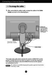
... plugged in as shown in the diagram. Notice Be cautious to External Devices To arrange the cables 1. L246WPM DC-OUT HDMI/DVI COMPONENT Y PB PR D-SUB 1 2 OUT AUDIO-OUT To connect HDMI, make sure that the audio cables are connected to the Cable Holder as show in the following figure. Cable Holder...
... plugged in as shown in the diagram. Notice Be cautious to External Devices To arrange the cables 1. L246WPM DC-OUT HDMI/DVI COMPONENT Y PB PR D-SUB 1 2 OUT AUDIO-OUT To connect HDMI, make sure that the audio cables are connected to the Cable Holder as show in the following figure. Cable Holder...
User Guide
Page 16
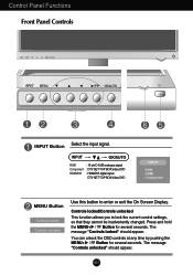
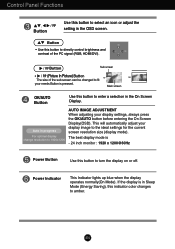
... enter or exit the On Screen Display. A15 INPUT OK/AUTO RGB Component HDMI/DVI : 15-pin D-SUB analogue signal : DTV SET-TOP BOX,Video,DVD : HDMI/DVI digital signal DTV SET-TOP BOX,Video,DVD INPUT RGB HDMI Component MENU Button Controls locked Controls unlocked Use this button to lock the current...
... enter or exit the On Screen Display. A15 INPUT OK/AUTO RGB Component HDMI/DVI : 15-pin D-SUB analogue signal : DTV SET-TOP BOX,Video,DVD : HDMI/DVI digital signal DTV SET-TOP BOX,Video,DVD INPUT RGB HDMI Component MENU Button Controls locked Controls unlocked Use this button to lock the current...
User Guide
Page 17
... ideal settings for the current screen resolution size (display mode). Button Sub screen • (Picture In Picture) Button The size of the PC signal (RGB, HDMI/DVI). Auto in progress For optimal display change resolution to 1920x1200 AUTO IMAGE ADJUSTMENT When adjusting your display image to amber. Power Indicator This Indicator...
... ideal settings for the current screen resolution size (display mode). Button Sub screen • (Picture In Picture) Button The size of the PC signal (RGB, HDMI/DVI). Auto in progress For optimal display change resolution to 1920x1200 AUTO IMAGE ADJUSTMENT When adjusting your display image to amber. Power Indicator This Indicator...
User Guide
Page 20
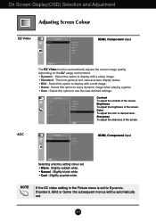
A19 On Screen Display(OSD) Selection and Adjustment Adjusting Screen Colour EZ Video HDMI, Component input ACC The EZ Video function automatically adjusts the screen image quality depending on the AV usage environment. • Dynamic : Select this option to ..., Mild or Game the subsequent menus will be automatically set . • Warm : Slightly reddish white. • Normal : Slightly bluish white. • Cool : Slightly purplish white. HDMI, Component input Selecting a factory setting colour set .
A19 On Screen Display(OSD) Selection and Adjustment Adjusting Screen Colour EZ Video HDMI, Component input ACC The EZ Video function automatically adjusts the screen image quality depending on the AV usage environment. • Dynamic : Select this option to ..., Mild or Game the subsequent menus will be automatically set . • Warm : Slightly reddish white. • Normal : Slightly bluish white. • Cool : Slightly purplish white. HDMI, Component input Selecting a factory setting colour set .
User Guide
Page 23
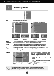
... horizontal screen size will also change. PC : Used when it is suitable for position. SCREEN ARC Auto-configure Clock Phase Position HDMI H-Position V-Position This function is for analogue signal input only. Left Moving the screen position horizontally. This function is connected with PC through... HDMI. A22 Down Video: Used when it is inputted at the RGB source input level, the Auto-Configure, Clock, Phase and Position ...
... horizontal screen size will also change. PC : Used when it is suitable for position. SCREEN ARC Auto-configure Clock Phase Position HDMI H-Position V-Position This function is for analogue signal input only. Left Moving the screen position horizontally. This function is connected with PC through... HDMI. A22 Down Video: Used when it is inputted at the RGB source input level, the Auto-Configure, Clock, Phase and Position ...
User Guide
Page 24
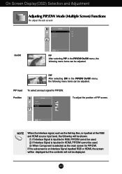
...the following menu items can be adjusted. If the sub-screen is an Interlace Signal inputted RGB or HDMI, the screen will be displayed but the contents will be shown. (1) If Interlace Signal is inputted ...in RGB, PIP/DW cannot be used. (2) If Interlace Signal is inputted at the RGB and HDMI source input level, the following menu items can be displayed. NOTE When the Interlace signal, such as.../Off PIP Input Position To adjust the position of PIP screen. A23 DW After selecting DW in HDMI, PIP/DW cannot be used. (3) When Component is selected as the Set-top Box, is ...
...the following menu items can be adjusted. If the sub-screen is an Interlace Signal inputted RGB or HDMI, the screen will be displayed but the contents will be shown. (1) If Interlace Signal is inputted ...in RGB, PIP/DW cannot be used. (2) If Interlace Signal is inputted at the RGB and HDMI source input level, the following menu items can be displayed. NOTE When the Interlace signal, such as.../Off PIP Input Position To adjust the position of PIP screen. A23 DW After selecting DW in HDMI, PIP/DW cannot be used. (3) When Component is selected as the Set-top Box, is ...
User Guide
Page 28
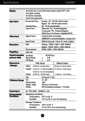
...Separate TTL, Positive/Negative Composite TTL, Positive/Negative SOG (Sync On Green), Digital(HDCP) Video Input Signal Input 15 pin D-Sub Connector HDMI/DVI connector(Digital), Component Input Form RGB Analog (0.7 Vp-p/ 75 ohm), Digital Resolution Plug&Play Max Recommend DDC 2B Analog : VESA...% non-Condensing Storage Conditions Temperature -20˚C to 60 ˚C Humidity 5 % to 90 % non-Condensing A27 Vertical Freq. Specifications L246WP Display 24 inches (61.3 cm) Flat Panel Active matrix-TFT LCD Anti-glare coating 24 inches viewable 0.270 mm pixel pitch Sync Input ...
...Separate TTL, Positive/Negative Composite TTL, Positive/Negative SOG (Sync On Green), Digital(HDCP) Video Input Signal Input 15 pin D-Sub Connector HDMI/DVI connector(Digital), Component Input Form RGB Analog (0.7 Vp-p/ 75 ohm), Digital Resolution Plug&Play Max Recommend DDC 2B Analog : VESA...% non-Condensing Storage Conditions Temperature -20˚C to 60 ˚C Humidity 5 % to 90 % non-Condensing A27 Vertical Freq. Specifications L246WP Display 24 inches (61.3 cm) Flat Panel Active matrix-TFT LCD Anti-glare coating 24 inches viewable 0.270 mm pixel pitch Sync Input ...

User Guide
Page 30
... - 83 kHz (Automatic) 56 - 75 Hz (Automatic) Separate TTL, Positive/Negative Composite TTL, Positive/Negative SOG (Sync On Green), Digital(HDCP) 15 pin D-Sub Connector HDMI/DVI connector(Digital), Component 0Input Form RGB Analog (0.7 Vp-p/ 75 ohm), Digital Resolution Plug&Play Max Recommend DDC 2B Analog : VESA 1920 x 1200 @60Hz Digital...
... - 83 kHz (Automatic) 56 - 75 Hz (Automatic) Separate TTL, Positive/Negative Composite TTL, Positive/Negative SOG (Sync On Green), Digital(HDCP) 15 pin D-Sub Connector HDMI/DVI connector(Digital), Component 0Input Form RGB Analog (0.7 Vp-p/ 75 ohm), Digital Resolution Plug&Play Max Recommend DDC 2B Analog : VESA 1920 x 1200 @60Hz Digital...

User Guide
Page 32
....98 79.98 75.00 75.00 65.29 74.04 65.96 60.02 75.02 60 60 60.45 59.95 * Recommend Mode HDMI Video INPUT Display Modes (Resolution) 1 480i 2 576i 3 480p 4 576p 5 720p 6 720p 7 1080i 8 1080i 9 1080p 10 1080p Horizontal Freq. (kHz) 15.75 15.62 31.50...
....98 79.98 75.00 75.00 65.29 74.04 65.96 60.02 75.02 60 60 60.45 59.95 * Recommend Mode HDMI Video INPUT Display Modes (Resolution) 1 480i 2 576i 3 480p 4 576p 5 720p 6 720p 7 1080i 8 1080i 9 1080p 10 1080p Horizontal Freq. (kHz) 15.75 15.62 31.50...

User Guide
Page 33
Data2 Shield 3 T. Data2- 4 T. S. Data1- 7 T. Data0+ 8 T. M. S. Clock+ 11 T. Specifications HDMI Type Pin Assignment No.1 No.19 No.2 No.18 Type A pin Signal Name 1 T. D. M. S. D. D. Data0 Shield 9 T. M. S. D. Data2+ 2 T. M. M. Data1+ 5 T. M. D. D. M. S. M. D. S. Data1 Shield 6 T. M. D. M. D. S. S. M. S. (Transition Minimized Differential Signaling) Type A pin 1 2 3 4 5 6 7 8 9 ...
Data2 Shield 3 T. Data2- 4 T. S. Data1- 7 T. Data0+ 8 T. M. S. Clock+ 11 T. Specifications HDMI Type Pin Assignment No.1 No.19 No.2 No.18 Type A pin Signal Name 1 T. D. M. S. D. D. Data0 Shield 9 T. M. S. D. Data2+ 2 T. M. M. Data1+ 5 T. M. D. D. M. S. M. D. S. Data1 Shield 6 T. M. D. M. D. S. S. M. S. (Transition Minimized Differential Signaling) Type A pin 1 2 3 4 5 6 7 8 9 ...
User Guide
Page 34
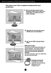
... COMPONENT Y PB PR D-SUB 2. Kensington Security Slot Connected to avoid surface damage. OUT AUDIO 2 1 DC-OUT HDMI/DVI COMPONENT Y PB PR D-SUB DC-OUT HDMI/DVI COMPONENT Y PB PR D-SUB 1 2 AUDIO OUT 3. Set up the VESA standard Stand Base. After moving the product to face downward, make sure to place ...
... COMPONENT Y PB PR D-SUB 2. Kensington Security Slot Connected to avoid surface damage. OUT AUDIO 2 1 DC-OUT HDMI/DVI COMPONENT Y PB PR D-SUB DC-OUT HDMI/DVI COMPONENT Y PB PR D-SUB 1 2 AUDIO OUT 3. Set up the VESA standard Stand Base. After moving the product to face downward, make sure to place ...


