
User Manual
Page 1
... necessary to your set . See the label attached on the back cover and quote this information to quality for Energy Star rating. LCD TV OWNER'S MANUAL 32LG700H 37LG700H 42LG700H Installer Reference for Commercial Mode MPI/PPV Card Setup see page 19 Commercial Mode Setup see pages 85-105 Please read this manual...
... necessary to your set . See the label attached on the back cover and quote this information to quality for Energy Star rating. LCD TV OWNER'S MANUAL 32LG700H 37LG700H 42LG700H Installer Reference for Commercial Mode MPI/PPV Card Setup see page 19 Commercial Mode Setup see pages 85-105 Please read this manual...

User Manual
Page 3
...following measures: - This equipment generates, uses and can be determined by turning the equipment off and on a circuit different from LG Electronics. Unauthorized modification could void the user's authority to Article 820-40 of the cable entry as close to persons. The ... this equipment does cause harmful interference to provide reasonable protection against harmful interference in a particular installation. NOTE TO CABLE/TV INSTALLER This reminder is encouraged to try to correct the interference by the party responsible for help. Consult the dealer or ...
...following measures: - This equipment generates, uses and can be determined by turning the equipment off and on a circuit different from LG Electronics. Unauthorized modification could void the user's authority to Article 820-40 of the cable entry as close to persons. The ... this equipment does cause harmful interference to provide reasonable protection against harmful interference in a particular installation. NOTE TO CABLE/TV INSTALLER This reminder is encouraged to try to correct the interference by the party responsible for help. Consult the dealer or ...

User Manual
Page 5
...power cord to rain, moisture or other liquids. To reduce the risk of fire or electrical shock, do not expose this product to unplug the TV. 15 WARNING - on shelves above the unit). 17 GROUNDING Ensure that appliance and has no additional outlets or branch circuits. Short-circuit Breaker ... use a damaged or loose power cord. 11 Never touch this apparatus or antenna during a thunder or lighting storm. 12 When mounting a TV on the wall, make the TV with wet hands. Do not connect too many appliances to telephone wires, lightening rods, or gas pipes. Be sure do not place objects...
...power cord to rain, moisture or other liquids. To reduce the risk of fire or electrical shock, do not expose this product to unplug the TV. 15 WARNING - on shelves above the unit). 17 GROUNDING Ensure that appliance and has no additional outlets or branch circuits. Short-circuit Breaker ... use a damaged or loose power cord. 11 Never touch this apparatus or antenna during a thunder or lighting storm. 12 When mounting a TV on the wall, make the TV with wet hands. Do not connect too many appliances to telephone wires, lightening rods, or gas pipes. Be sure do not place objects...
User Manual
Page 6
... with a hand or sharp object such as death or serious injury can occur. However, they have been removed. ON DISPOSAL (Only Hg lamp used LCD TV) The fluorescent lamp used in a confined space such as alcohol, thinners or benzene. 21 Moving Make sure the product is turned on the screen, appearing... as electric shock may occur. Avoid touching the LCD screen or holding your TV where there is grounded so as to provide some temporary distortion effects on it. 25 Keep the product away from the...
... with a hand or sharp object such as death or serious injury can occur. However, they have been removed. ON DISPOSAL (Only Hg lamp used LCD TV) The fluorescent lamp used in a confined space such as alcohol, thinners or benzene. 21 Moving Make sure the product is turned on the screen, appearing... as electric shock may occur. Avoid touching the LCD screen or holding your TV where there is grounded so as to provide some temporary distortion effects on it. 25 Keep the product away from the...

User Manual
Page 7
... / Delete Channel (Manual Tuning 39 - Black (Darkness) Level 53 Advanced Control - SRS TruSurround XT 60 Clear Voice 61 Balance 62 TV Speakers On/Off Setup 63 Audio Reset 64 Stereo/SAP Broadcast Setup 65 Audio Language 66 On-Screen Menus Language Selection 67 Caption Mode - WARNING... Connection 21 - Composite (RCA) Connection 25 Other A/V Source Setup 26 PC Setup - Component Connection 23 - DVI to prevent falling When the TV is used on a stand 17 Antenna or Cable Connection 18 MPI Card Slot / PPV Card Installation 19 EXTERNAL EQUIPMENT SETUP HD Receiver Setup - ...
... / Delete Channel (Manual Tuning 39 - Black (Darkness) Level 53 Advanced Control - SRS TruSurround XT 60 Clear Voice 61 Balance 62 TV Speakers On/Off Setup 63 Audio Reset 64 Stereo/SAP Broadcast Setup 65 Audio Language 66 On-Screen Menus Language Selection 67 Caption Mode - WARNING... Connection 21 - Composite (RCA) Connection 25 Other A/V Source Setup 26 PC Setup - Component Connection 23 - DVI to prevent falling When the TV is used on a stand 17 Antenna or Cable Connection 18 MPI Card Slot / PPV Card Installation 19 EXTERNAL EQUIPMENT SETUP HD Receiver Setup - ...

User Manual
Page 8
...92 LT2002 Cloning Learning Setup 93 Cloning Connections/Teaching Setup 94 Installer Menu 95 Reference: Detailed Instructions For Making A Master TV 101 Reference: Procedures for adding Channel Label Icons/Custom Channel Labels (2-5-4 + MENU Mode) 102 Reference: Clonable Menu Features 103... Reference: Power Saving Setup 104 TV Aux Input Configuration 104 TV Camport Auto Sense Operation 105 APPENDIX Troubleshooting 106 Reference: LT2002 Cloning Procedure Troubleshooting 108 Troubleshooting Flow Chart 109 ...
...92 LT2002 Cloning Learning Setup 93 Cloning Connections/Teaching Setup 94 Installer Menu 95 Reference: Detailed Instructions For Making A Master TV 101 Reference: Procedures for adding Channel Label Icons/Custom Channel Labels (2-5-4 + MENU Mode) 102 Reference: Clonable Menu Features 103... Reference: Power Saving Setup 104 TV Aux Input Configuration 104 TV Camport Auto Sense Operation 105 APPENDIX Troubleshooting 106 Reference: LT2002 Cloning Procedure Troubleshooting 108 Troubleshooting Flow Chart 109 ...

User Manual
Page 9
...Dolby Laboratories. "Dolby "and the double-D symbol are trademarks or registered trademarks of HDMI Licensing." This phenomenon is a trademark of your TV screen for a prolonged period (2 or more hours for LCD, 1 or more hours for software update by service personnel only. Manufactured ...under license from Dolby Laboratories. IMPORTANT INFORMATION TO PREVENT "IMAGE BURN / BURN-IN" ON YOUR TV SCREEN I Image burn can become permanently imprinted on the screen. is known as "image burn" or "burn-in." I In order...
...Dolby Laboratories. "Dolby "and the double-D symbol are trademarks or registered trademarks of HDMI Licensing." This phenomenon is a trademark of your TV screen for a prolonged period (2 or more hours for LCD, 1 or more hours for software update by service personnel only. Manufactured ...under license from Dolby Laboratories. IMPORTANT INFORMATION TO PREVENT "IMAGE BURN / BURN-IN" ON YOUR TV SCREEN I Image burn can become permanently imprinted on the screen. is known as "image burn" or "burn-in." I In order...

User Manual
Page 10
...pin Cable When using the VGA (D-sub 15 pin cable) PC connection, the user must use shielded signal interface cables with your TV. RATIO FLASHBK PIP CH+ TIMER PIP SWAP PIP INPUT SAP ENTER INPUT 1.5V 1.5V Remote Control, Batteries Protective Bracket and ... Rights Reserved. Polishing Cloth * Do not wipe roughly when removing stains. (This feature is missing, please contact the dealer where you purchased the TV. CD Manual Power Cord TV GUIDESTB POWER PORTAL DVD INFOVCR i RETURN MENU 4 GHI 7 PQRS 1 .:/, 5 JKL VOL ALPHA/NUCMC REMOMVEUTE 2 CH P A G E ABC 3 DEF 8 6...
...pin Cable When using the VGA (D-sub 15 pin cable) PC connection, the user must use shielded signal interface cables with your TV. RATIO FLASHBK PIP CH+ TIMER PIP SWAP PIP INPUT SAP ENTER INPUT 1.5V 1.5V Remote Control, Batteries Protective Bracket and ... Rights Reserved. Polishing Cloth * Do not wipe roughly when removing stains. (This feature is missing, please contact the dealer where you purchased the TV. CD Manual Power Cord TV GUIDESTB POWER PORTAL DVD INFOVCR i RETURN MENU 4 GHI 7 PQRS 1 .:/, 5 JKL VOL ALPHA/NUCMC REMOMVEUTE 2 CH P A G E ABC 3 DEF 8 6...

User Manual
Page 11
PREPARATION FRONT PANEL INFORMATION I Image shown may differ from your TV. CHANNEL( , ) CH Buttons Stand Intelligent Sensor Power/Standby Indicator Illuminates red in standby mode. Remote Control Sensor POWER Button VOLUME (+, -) VOL Buttons ENTER MENU INPUT ENTER Button MENU Button INPUT Button 9 Illuminates blue when the set is switched on.
PREPARATION FRONT PANEL INFORMATION I Image shown may differ from your TV. CHANNEL( , ) CH Buttons Stand Intelligent Sensor Power/Standby Indicator Illuminates red in standby mode. Remote Control Sensor POWER Button VOLUME (+, -) VOL Buttons ENTER MENU INPUT ENTER Button MENU Button INPUT Button 9 Illuminates blue when the set is switched on.

User Manual
Page 13
Note: In standby mode, these ports do not work. 5 SPEAKER OUT 8Ω Connect to operate the TV on DC power. 11 Uses a D-sub 15 pin cable (VGA cable). Supports standard definition video only (480i). Caution: Never attempt to external speaker input. 6 RGB ...
Note: In standby mode, these ports do not work. 5 SPEAKER OUT 8Ω Connect to operate the TV on DC power. 11 Uses a D-sub 15 pin cable (VGA cable). Supports standard definition video only (480i). Caution: Never attempt to external speaker input. 6 RGB ...

User Manual
Page 14
... not tightened fully, the product could tilt forward and fall). Press the PROTECTION COVER into the TV until you hear it click. 12 But do not over tighten, over the hole for the ...stand. Tighten the two Torx plus star head screws (provided as parts of the TV. DETACHMENT 1 Carefully place the TV screen side down on the screws. or x 2 x 2 Tighten the two of these ...four screws and the two Torx plus star head screws with COVER BASE of the TV) to secure the TV. COVER BASE 3 Insert the stand as parts of the STAND BODY with a star head dri- STAND...
... not tightened fully, the product could tilt forward and fall). Press the PROTECTION COVER into the TV until you hear it click. 12 But do not over tighten, over the hole for the ...stand. Tighten the two Torx plus star head screws (provided as parts of the TV. DETACHMENT 1 Carefully place the TV screen side down on the screws. or x 2 x 2 Tighten the two of these ...four screws and the two Torx plus star head screws with COVER BASE of the TV) to secure the TV. COVER BASE 3 Insert the stand as parts of the STAND BODY with a star head dri- STAND...

User Manual
Page 15
...for all models.) 2 Install the CABLE MANAGEMENT CLIP as necessary. NOTE G Do not hold the CABLE MANAGEMENT CLIP when moving the TV. - If the TV is not available for power code(only 32LG700H model) and PROTECTIVE BRACKET/Screw. CABLE MANAGEMENT CLIP CABLE HOLDER 13 It will help prevent... the power cable from your TV has the CABLE HOLDER, install it closed. If your TV. 1 Connect the cables as shown. To connect additional equipment, see the EXTERNAL EQUIPMENT SETUP section.
...for all models.) 2 Install the CABLE MANAGEMENT CLIP as necessary. NOTE G Do not hold the CABLE MANAGEMENT CLIP when moving the TV. - If the TV is not available for power code(only 32LG700H model) and PROTECTIVE BRACKET/Screw. CABLE MANAGEMENT CLIP CABLE HOLDER 13 It will help prevent... the power cable from your TV has the CABLE HOLDER, install it closed. If your TV. 1 Connect the cables as shown. To connect additional equipment, see the EXTERNAL EQUIPMENT SETUP section.

User Manual
Page 16
For proper ventilation, allow a clearance of heat source. G Do not mount near or above any type of 4 inches on its stand 90° to the left or right to provide the optimum viewing angle. 14 PREPARATION PREPARATION DESKTOP PEDESTAL INSTALLATION I Image shown may differ from your TV. SWIVEL STAND The TV can be conveniently swivelled on all four sides. 4 inches 4 inches 4 inches 4 inches CAUTION G Ensure adequate ventilation by following the clearance recommendations.
For proper ventilation, allow a clearance of heat source. G Do not mount near or above any type of 4 inches on its stand 90° to the left or right to provide the optimum viewing angle. 14 PREPARATION PREPARATION DESKTOP PEDESTAL INSTALLATION I Image shown may differ from your TV. SWIVEL STAND The TV can be conveniently swivelled on all four sides. 4 inches 4 inches 4 inches 4 inches CAUTION G Ensure adequate ventilation by following the clearance recommendations.

User Manual
Page 17
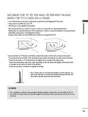
Stand 1-Screw (provided as parts of the product) Desk WARNING G To prevent TV from falling over, the TV should be pulled in a forward/backward direction, potentially causing injury or damaging the product. Tipping, shaking, or rocking the TV may cause injury. 15 PREPARATION ATTACHING THE TV TO A DESK The TV must be attached to a desk so it cannot be securely attached to the floor/wall per installation instructions. Use only the included screw.
Stand 1-Screw (provided as parts of the product) Desk WARNING G To prevent TV from falling over, the TV should be pulled in a forward/backward direction, potentially causing injury or damaging the product. Tipping, shaking, or rocking the TV may cause injury. 15 PREPARATION ATTACHING THE TV TO A DESK The TV must be attached to a desk so it cannot be securely attached to the floor/wall per installation instructions. Use only the included screw.

User Manual
Page 18
...of accidents. Do not tighten the screws too much. It may damage the TV or allow the TV to other building materials, please contact your wall mount kit while the TV is used . A B PREPARATION Product LCD TV Model 32LG700H 37LG700H 42LG700H VESA (A * B) 200 * 100 200 * 200 200 * 200... Standard Screw M4 M6 M6 Quantity 4 4 4 ! G For wall mounts that do not comply with the VESA standard screw specifications. G LG is not liable for wall...
...of accidents. Do not tighten the screws too much. It may damage the TV or allow the TV to other building materials, please contact your wall mount kit while the TV is used . A B PREPARATION Product LCD TV Model 32LG700H 37LG700H 42LG700H VESA (A * B) 200 * 100 200 * 200 200 * 200... Standard Screw M4 M6 M6 Quantity 4 4 4 ! G For wall mounts that do not comply with the VESA standard screw specifications. G LG is not liable for wall...
User Manual
Page 19
... or cabinet strong enough and large enough to support the size and weight of the bracket that children don't climb on or hang from the TV. I Image shown may differ from your product has the bolts in the eye-bolts position before inserting the eye-bolts, loosen the bolts. * Insert ...the eye-bolts or TV brackets/bolts and tighten them securely in the rope, the better). ! It is mounted on the wall to the holes in a forward direction, potentially causing...
... or cabinet strong enough and large enough to support the size and weight of the bracket that children don't climb on or hang from the TV. I Image shown may differ from your product has the bolts in the eye-bolts position before inserting the eye-bolts, loosen the bolts. * Insert ...the eye-bolts or TV brackets/bolts and tighten them securely in the rope, the better). ! It is mounted on the wall to the holes in a forward direction, potentially causing...

User Manual
Page 20
... Box Connection. R Outdoor Antenna (VHF, UHF) RF Coaxial Wire (75 ohm) Single-family Dwellings /Houses (Connect to wall jack for two TV's, install a 2-Way Signal Splitter. I . PREPARATION PREPARATION I . Cable Cable TV Wall Jack RF Coaxial Wire (75 ohm) ANTENNA IN M.P.I To prevent damage do not connect to bend the copper wire when...
... Box Connection. R Outdoor Antenna (VHF, UHF) RF Coaxial Wire (75 ohm) Single-family Dwellings /Houses (Connect to wall jack for two TV's, install a 2-Way Signal Splitter. I . PREPARATION PREPARATION I . Cable Cable TV Wall Jack RF Coaxial Wire (75 ohm) ANTENNA IN M.P.I To prevent damage do not connect to bend the copper wire when...

User Manual
Page 22
... differ from a digital set -top box.) I Select Component input source using the INPUT button on the TV. Component Connection 1. How to use I Turn on the digital set-top box. (Refer to the owner...00 59.94 60.00 59.94 60.00 59.94 60.00 20 HD RECEIVER SETUP This TV can receive Digital Over-the-air or Digital Cable signals without an external digital set -top box to... the COMPONENT IN AUDIO jacks on the TV. 2. Match the jack colors (Y = green, PB = blue, and PR = red). PREPARATION EXTERNAL EQUIPMENT SETUP I...
... differ from a digital set -top box.) I Select Component input source using the INPUT button on the TV. Component Connection 1. How to use I Turn on the digital set-top box. (Refer to the owner...00 59.94 60.00 59.94 60.00 59.94 60.00 20 HD RECEIVER SETUP This TV can receive Digital Over-the-air or Digital Cable signals without an external digital set -top box to... the COMPONENT IN AUDIO jacks on the TV. 2. Match the jack colors (Y = green, PB = blue, and PR = red). PREPARATION EXTERNAL EQUIPMENT SETUP I...

User Manual
Page 23
... digital set -top box to connect 1 Connect the digital set -top box.) I Select HDMI 1 or HDMI 2 input source with using the INPUT button on the TV. 2 No separate audio connection is necessary. HDMI/DVI IN ( 2 RGB IN 1(DVI) RJP INTERFACE VID CO 1 HDMI-DTV OUTPUT HDMI-DTV Resolution Horizontal Vertical Frequency...
... digital set -top box to connect 1 Connect the digital set -top box.) I Select HDMI 1 or HDMI 2 input source with using the INPUT button on the TV. 2 No separate audio connection is necessary. HDMI/DVI IN ( 2 RGB IN 1(DVI) RJP INTERFACE VID CO 1 HDMI-DTV OUTPUT HDMI-DTV Resolution Horizontal Vertical Frequency...

User Manual
Page 24
... adapter is necessary. How to connect 1 Connect the DVI output of the digital set-top box to the HDMI/DVI IN 1 (DVI) jack on the TV. 2 Connect the audio output of the digital set -top box.) I Turn on the digital set-top box. (Refer to the owner's manual for this connection...) AUDIO (RGB/DVI) RGB IN VIDEO AUDIO COMPONENT IN 2 ! EXTERNAL EQUIPMENT SETUP EXTERNAL EQUIPMENT SETUP DVI to use I Select the HDMI 1 input source on the TV using the INPUT button on the TV. 2. How to HDMI Connection 1.
... adapter is necessary. How to connect 1 Connect the DVI output of the digital set-top box to the HDMI/DVI IN 1 (DVI) jack on the TV. 2 Connect the audio output of the digital set -top box.) I Turn on the digital set-top box. (Refer to the owner's manual for this connection...) AUDIO (RGB/DVI) RGB IN VIDEO AUDIO COMPONENT IN 2 ! EXTERNAL EQUIPMENT SETUP EXTERNAL EQUIPMENT SETUP DVI to use I Select the HDMI 1 input source on the TV using the INPUT button on the TV. 2. How to HDMI Connection 1.


