Setup Guide
Page 3
... filled with an exact replacement part by the hanging power and signal cables on the back of the polarized or grounding-type plug. Pay particular attention to grasp the plug when unplugging the power cord. Be sure to plugs, wall outlets, and the point where the cord exits the appliance. Do not expose to rain or moisture, does not operate normally, or has been...
... filled with an exact replacement part by the hanging power and signal cables on the back of the polarized or grounding-type plug. Pay particular attention to grasp the plug when unplugging the power cord. Be sure to plugs, wall outlets, and the point where the cord exits the appliance. Do not expose to rain or moisture, does not operate normally, or has been...
Setup Guide
Page 4
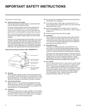
... plugged in a confined space such as tiny red, green, or blue spots. Antenna Grounding According to carry larger TVs. Do not cover the TV with cloth or other electric light or power circuits or where it is common for long periods of the National Electrical Code (NEC) in excessively dusty places. 26. Dot Defect The LCD panel is connected to operate...
... plugged in a confined space such as tiny red, green, or blue spots. Antenna Grounding According to carry larger TVs. Do not cover the TV with cloth or other electric light or power circuits or where it is common for long periods of the National Electrical Code (NEC) in excessively dusty places. 26. Dot Defect The LCD panel is connected to operate...
Setup Guide
Page 5
... Upgrading TV/PTC Software using a USB Memory Device 42 Downloading a Splash Screen using a USB Memory Device 43 Power Consumption Settings 44 - 45 TV Camport Auto Sense Operation 46 TV Aux Input Configuration 47 b-LAN Setup & Overview 48 RJP Model List and Input Auto-sensing Hierarchy . . . . . 49 Resetting Factory Defaults on the TV(s 50 LD320H/LD325H & LD340H/LD345H Rear Jack Panel . . 51 Side Connections Panel / RF Antenna & MPI Connections 52 Troubleshooting 53 - 56 General Troubleshooting 53 Troubleshooting Flow Chart 54 Commercial Mode...
... Upgrading TV/PTC Software using a USB Memory Device 42 Downloading a Splash Screen using a USB Memory Device 43 Power Consumption Settings 44 - 45 TV Camport Auto Sense Operation 46 TV Aux Input Configuration 47 b-LAN Setup & Overview 48 RJP Model List and Input Auto-sensing Hierarchy . . . . . 49 Resetting Factory Defaults on the TV(s 50 LD320H/LD325H & LD340H/LD345H Rear Jack Panel . . 51 Side Connections Panel / RF Antenna & MPI Connections 52 Troubleshooting 53 - 56 General Troubleshooting 53 Troubleshooting Flow Chart 54 Commercial Mode...
Setup Guide
Page 6
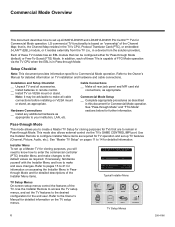
... (Channel, Picture, Audio, etc.). See "Pass-through Mode (default) or Free-To-Guest (FTG) Mode. Pass-through Mode. Refer to pages 15 to make and save changes. Refer to configure Installer Menu items as required. Use the Installer Remote to the Owner's Manual for Commercial Mode operation. LG commercial TV functionality is based on TV installation and hardware and cable connections. If necessary, familiarize yourself with the Installer Menu and how to make all rear jack panel...
... (Channel, Picture, Audio, etc.). See "Pass-through Mode (default) or Free-To-Guest (FTG) Mode. Pass-through Mode. Refer to pages 15 to make and save changes. Refer to configure Installer Menu items as required. Use the Installer Remote to the Owner's Manual for Commercial Mode operation. LG commercial TV functionality is based on TV installation and hardware and cable connections. If necessary, familiarize yourself with the Installer Menu and how to make all rear jack panel...
Setup Guide
Page 10
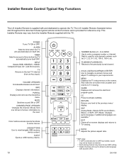
... will reset to the previously tuned channel. VOLUME UP/DOWN Increases/decreases sound level. PORTAL Displays and removes the interactive menu. CHANNEL/PAGE UP/DOWN Changes the channel. FLASHBK (FLASHBACK) Returns to default audio language with a power off/on channel. • Each analog channel may vary from the Installer Remote supplied with the TV. Color buttons access special functions in some menus. USB BUTTONS Use to enter a program number or channel. EJECT Ejects a USB memory device. 10 ALARM TIMER INPUT TV...
... will reset to the previously tuned channel. VOLUME UP/DOWN Increases/decreases sound level. PORTAL Displays and removes the interactive menu. CHANNEL/PAGE UP/DOWN Changes the channel. FLASHBK (FLASHBACK) Returns to default audio language with a power off/on channel. • Each analog channel may vary from the Installer Remote supplied with the TV. Color buttons access special functions in some menus. USB BUTTONS Use to enter a program number or channel. EJECT Ejects a USB memory device. 10 ALARM TIMER INPUT TV...
Setup Guide
Page 12
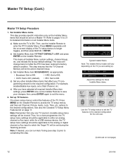
... Setup Procedure 1. e) After you have adjusted all required Installer Menu item settings, press ENTER once on the Installer Remote. b) Set Installer Menu item 117 FACT DEFAULT to 001 and press ENTER on the Installer Remote to save your TV programming network to access the TV setup menus, and then set Channel, Picture, Audio, Lock, Time, etc. Set Installer Menu items. This step provides specific instruction only on the Installer Menu items that only one TV source's clonable setup menu settings will be set on the Installer Remote...
... Setup Procedure 1. e) After you have adjusted all required Installer Menu item settings, press ENTER once on the Installer Remote. b) Set Installer Menu item 117 FACT DEFAULT to 001 and press ENTER on the Installer Remote to save your TV programming network to access the TV setup menus, and then set Channel, Picture, Audio, Lock, Time, etc. Set Installer Menu items. This step provides specific instruction only on the Installer Menu items that only one TV source's clonable setup menu settings will be set on the Installer Remote...
Setup Guide
Page 16
.... Set to 1 to disable HDMI 1. Set to 0 to enable On/Off Timers. Set to 1 to enable Auto Turn ON when AC power is turned ON. (Set to 255 to 0). Chooses custom background color for the Channel-Time display. Set to 1 to enable display panel Component Video 1 input jacks. Set to 1 to which the TV will respond. Determines an additional IR code scheme to enable Sleep Timer. If set to use volume level before automatic shutoff. Set to 1 to enable display panel Video 1 input...
.... Set to 1 to disable HDMI 1. Set to 0 to enable On/Off Timers. Set to 1 to enable Auto Turn ON when AC power is turned ON. (Set to 255 to 0). Chooses custom background color for the Channel-Time display. Set to 1 to enable display panel Component Video 1 input jacks. Set to 1 to which the TV will respond. Determines an additional IR code scheme to enable Sleep Timer. If set to use volume level before automatic shutoff. Set to 1 to enable display panel Video 1 input...
Setup Guide
Page 17
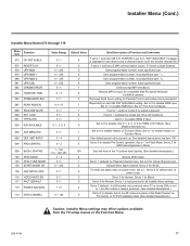
... locked out, IR is still functional. 1 Set to 1 to enable HDMI 2 input. 0 Set to 0 to be compatible with PC-based Windowscontrolled systems. 0 Removes block hours setting for Blank. 0 Set to the RF channel number of the TV picture back lighting. (See detailed descriptions.) 4 Selects ATSC band. 1 Set to enable feature on Function Menu. Set to 1 to 1 (default) for Virtual Channel scan. 0 Selects Minor Start Channel. Set to 17 for Auto Configure. 1 If set to 1, audio...
... locked out, IR is still functional. 1 Set to 1 to enable HDMI 2 input. 0 Set to 0 to be compatible with PC-based Windowscontrolled systems. 0 Removes block hours setting for Blank. 0 Set to the RF channel number of the TV picture back lighting. (See detailed descriptions.) 4 Selects ATSC band. 1 Set to enable feature on Function Menu. Set to 1 to 1 (default) for Virtual Channel scan. 0 Selects Minor Start Channel. Set to 17 for Auto Configure. 1 If set to 1, audio...
Setup Guide
Page 19
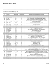
... IR codes based on "bed number" in a multi-TV single room installation. CH. If set to 0, the Sleep Timer is not available. 016 - When set to 0, only those channels that are OFF when the TV is connected to enable display panel rear Aux (Video 1) input. Step size of channel 0. CAMPORT EN. (Camera Port Enable) Set to 1 to 99 for MPI. REAR AUX EN. (Rear Aux Enable) Set to 1 to side Video input. AUTO CAMPORT Set to...
... IR codes based on "bed number" in a multi-TV single room installation. CH. If set to 0, the Sleep Timer is not available. 016 - When set to 0, only those channels that are OFF when the TV is connected to enable display panel rear Aux (Video 1) input. Step size of channel 0. CAMPORT EN. (Camera Port Enable) Set to 1 to 99 for MPI. REAR AUX EN. (Rear Aux Enable) Set to 1 to side Video input. AUTO CAMPORT Set to...
Setup Guide
Page 20
... rear RGB input on MPI async port). FOR. Note: Not linked to serial number. 082 - Note: Not linked to serial number. 081 - If set to the RJP, both digital video and audio are expected via the HDMI cable. If no audio will not appear. Set to 0 to Color Chart: 0 = Black 3 = Cyan 6 = Yellow 1 = Blue 4 = Red 7 = White 2 = Green 5 = Violet Note: If foreground color and background color are disabled, Power button remains enabled. CH-TIME (Channel-Time Display Foreground Color) Set according to disable custom color...
... rear RGB input on MPI async port). FOR. Note: Not linked to serial number. 082 - Note: Not linked to serial number. 081 - If set to the RJP, both digital video and audio are expected via the HDMI cable. If no audio will not appear. Set to 0 to Color Chart: 0 = Black 3 = Cyan 6 = Yellow 1 = Blue 4 = Red 7 = White 2 = Green 5 = Violet Note: If foreground color and background color are disabled, Power button remains enabled. CH-TIME (Channel-Time Display Foreground Color) Set according to disable custom color...
Setup Guide
Page 21
... channel number of all Installer Menu item settings. ASP. VIDEO MUTE EN (Video Mute Enable) Set to 1, the b-LAN module is turned ON. POWER SAVINGS Default set to 0 for further information. 118 - If set to customize each TV's RJP setup based on the TV(s)," for Normal. ASP. Analog audio is turned OFF. Settings 1, 2, 5, and 6 allow the lodge staff to 3-the power circuitry for Pro:Centric or TV E-Z Installation (splash screen, configuration, or firmware...
... channel number of all Installer Menu item settings. ASP. VIDEO MUTE EN (Video Mute Enable) Set to 1, the b-LAN module is turned ON. POWER SAVINGS Default set to 0 for further information. 118 - If set to customize each TV's RJP setup based on the TV(s)," for Normal. ASP. Analog audio is turned OFF. Settings 1, 2, 5, and 6 allow the lodge staff to 3-the power circuitry for Pro:Centric or TV E-Z Installation (splash screen, configuration, or firmware...
Setup Guide
Page 23
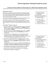
... be in Pass-through Mode. • Learning and Teaching is only possible between identical model TVs. • If using a USB memory device, ensure the USB device has been formatted with FAT format. • For both Master and Target TVs-If using a clone programmer, ensure the TV is tuned to either an Aux input or an analog (not a digital) channel. • LT2002 only...
... be in Pass-through Mode. • Learning and Teaching is only possible between identical model TVs. • If using a USB memory device, ensure the USB device has been formatted with FAT format. • For both Master and Target TVs-If using a clone programmer, ensure the TV is tuned to either an Aux input or an analog (not a digital) channel. • LT2002 only...
Setup Guide
Page 27
... power cord for 2-5-5 + MENU Mode during Teaching. To execute item, press Enter. 206-4186 27 Tune/set the TV to an analog channel or Aux input (ideally the same source tuned for 15 seconds. 7. Ensure the correct Memory CBank(X) is done, disconnect the MPI cable from the Target TV, turn ON the TV. When Teaching is selected on -screen display of the TV setup...
... power cord for 2-5-5 + MENU Mode during Teaching. To execute item, press Enter. 206-4186 27 Tune/set the TV to an analog channel or Aux input (ideally the same source tuned for 15 seconds. 7. Ensure the correct Memory CBank(X) is done, disconnect the MPI cable from the Target TV, turn ON the TV. When Teaching is selected on -screen display of the TV setup...
Setup Guide
Page 28
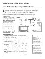
... on screen instructions Status Indicator MPI • green • red Color Reset battery ok battery low Blink pattern • slow power on no communications • heartbeat power on communications ok LT2002 Clone Programmer ® QuickSet II Programmer LT2002 ZENITH ELECTRONICS CORPORATION, LINCOLNSHIRE, ILLINOIS, USA Learn Setup from the Clone Selection Menu; MPI Cable Ferrite Core (TDK, ZCAT 2035-0930) Connect cable to an analog channel or Aux input...
... on screen instructions Status Indicator MPI • green • red Color Reset battery ok battery low Blink pattern • slow power on no communications • heartbeat power on communications ok LT2002 Clone Programmer ® QuickSet II Programmer LT2002 ZENITH ELECTRONICS CORPORATION, LINCOLNSHIRE, ILLINOIS, USA Learn Setup from the Clone Selection Menu; MPI Cable Ferrite Core (TDK, ZCAT 2035-0930) Connect cable to an analog channel or Aux input...
Setup Guide
Page 29
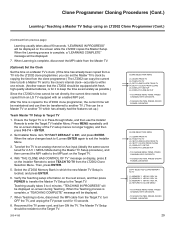
... for 2-5-5 + MENU Mode during Teaching. TO CHANGE MENU ITEMS, PRESS CHANNEL KEYS OR DIGITS. - TO CHANGE MENU ITEMS, PRESS CHANNEL KEYS OR DIGITS. - When the value changes back to 0, press ENTER again to the MPI port on -screen display of the TV setup menus no longer toggles, and then press 9-8-7-6 + ENTER. 2. TO EXECUTE ITEM, PRESS ON/OFF, POWER, OR ENTER. 29 Tune/set directly, the current time needs to...
... for 2-5-5 + MENU Mode during Teaching. TO CHANGE MENU ITEMS, PRESS CHANNEL KEYS OR DIGITS. - TO CHANGE MENU ITEMS, PRESS CHANNEL KEYS OR DIGITS. - When the value changes back to 0, press ENTER again to the MPI port on -screen display of the TV setup menus no longer toggles, and then press 9-8-7-6 + ENTER. 2. TO EXECUTE ITEM, PRESS ON/OFF, POWER, OR ENTER. 29 Tune/set directly, the current time needs to...
Setup Guide
Page 35
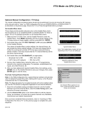
FTG Mode via CPU (Cont.) Optional Manual Configuration / TV Setup The manual configuration procedures below should be enabled unless you begin. Set any other Installer Menu items that affect your TV programming network to the Physical Channels from the TV Channel Map. After you have completed these Installer Menu items. CHANNEL Auto Tuning Manual Tuning Channel Edit Channel Label Move Enter Use Channel Menu options to run Auto Tuning and edit the channel lineup...
FTG Mode via CPU (Cont.) Optional Manual Configuration / TV Setup The manual configuration procedures below should be enabled unless you begin. Set any other Installer Menu items that affect your TV programming network to the Physical Channels from the TV Channel Map. After you have completed these Installer Menu items. CHANNEL Auto Tuning Manual Tuning Channel Edit Channel Label Move Enter Use Channel Menu options to run Auto Tuning and edit the channel lineup...
Setup Guide
Page 36
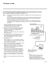
... EBL using a USB-to FTG Mode). "Read" the current FTG Installer Menu settings from Pass-through Mode to -TTL serial cable (TTL-232R-5V-AJ). Note: Up to 141 logical channels can be used to -TV connection. Laptop PC 6. Build an FTG Channel Map using a direct PC-to configure the EBL. 2. Rear Jack Panel REMOTE CONTROL OUT AUDIO IN (RGB/DVI) RS-232C IN (SERVICE ONLY) ......... AV IN 1 VIDEO L/MONO-AUDIO-R ANTENNA IN GAME CONTROL...
... EBL using a USB-to FTG Mode). "Read" the current FTG Installer Menu settings from Pass-through Mode to -TTL serial cable (TTL-232R-5V-AJ). Note: Up to 141 logical channels can be used to -TV connection. Laptop PC 6. Build an FTG Channel Map using a direct PC-to configure the EBL. 2. Rear Jack Panel REMOTE CONTROL OUT AUDIO IN (RGB/DVI) RS-232C IN (SERVICE ONLY) ......... AV IN 1 VIDEO L/MONO-AUDIO-R ANTENNA IN GAME CONTROL...
Setup Guide
Page 53
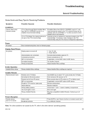
...; Turn TV ON. • Power failure? See troubleshooting flow chart on TV. Connect antenna/cable signal to channels included in battery compartment. Encrypted program. Wrong tuning band. Erratic Operation Installer Menu setup. Remote not in room. MPI not connected. Too much light in TV Mode. Point remote at IR remote sensor. Remove obstructions. Note: For other devices' operating guide(s). 206-4186 53 OVERIDE to 1 to allow access for Resolving Problems Symptom Installation Cannot direct enter channel number. Display Panel Picture No picture. Antenna/cable...
...; Turn TV ON. • Power failure? See troubleshooting flow chart on TV. Connect antenna/cable signal to channels included in battery compartment. Encrypted program. Wrong tuning band. Erratic Operation Installer Menu setup. Remote not in room. MPI not connected. Too much light in TV Mode. Point remote at IR remote sensor. Remove obstructions. Note: For other devices' operating guide(s). 206-4186 53 OVERIDE to 1 to allow access for Resolving Problems Symptom Installation Cannot direct enter channel number. Display Panel Picture No picture. Antenna/cable...
Setup Guide
Page 56
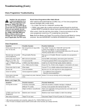
... possible with identical model TVs. Either of these actions will damage the clone programmer and, if applicable, the PPV card. Clone menu does not display on clone programmer. Clone not working. LT2002: Press RESET on TV screen, TLL1100A shows error message, or LT2002 LED does not blink. Connect MPI cord properly, and ensure good connection. Set time on page 23. Clone programmer problem. • Try...
... possible with identical model TVs. Either of these actions will damage the clone programmer and, if applicable, the PPV card. Clone menu does not display on clone programmer. Clone not working. LT2002: Press RESET on TV screen, TLL1100A shows error message, or LT2002 LED does not blink. Connect MPI cord properly, and ensure good connection. Set time on page 23. Clone programmer problem. • Try...

Setup Guide
Page 57
... receive cable programming signals. COMPOSITE VIDEO Typical video jack, uses one speaker, all the speakers play the same audio. DIGITAL TELEVISION High-resolution, cinema-quality television signals transmitted digitally. Refers to television signals that connects a 2-wire 300 ohm antenna to configure/control TV via RF distribution system. SIGNAL Picture and sound traveling through using three separate colors: Red, Green, and Blue. VIRTUAL CHANNEL NUMBER A re-mapped channel number. COMPONENT VIDEO Uses three wires for transporting three-color video signals. Additional...
... receive cable programming signals. COMPOSITE VIDEO Typical video jack, uses one speaker, all the speakers play the same audio. DIGITAL TELEVISION High-resolution, cinema-quality television signals transmitted digitally. Refers to television signals that connects a 2-wire 300 ohm antenna to configure/control TV via RF distribution system. SIGNAL Picture and sound traveling through using three separate colors: Red, Green, and Blue. VIRTUAL CHANNEL NUMBER A re-mapped channel number. COMPONENT VIDEO Uses three wires for transporting three-color video signals. Additional...


