
Operation Manual
Page 1
Model CMOS-320/CMOS-220 Serial number US Residence Only Register Online Register your new Universal Camera. Familiarity with installation and operation procedures will help you call upon your Kenwood dealer for information or service on the warranty card, and in the space provided below. For your ...records Record the serial number, found on the back of the unit, in the spaces designated on the product. CMOS-320 CMOS-220 UNIVERSAL MULTI-VIEW CAMERA/ UNIVERSAL REAR VIEW CAMERA...
Model CMOS-320/CMOS-220 Serial number US Residence Only Register Online Register your new Universal Camera. Familiarity with installation and operation procedures will help you call upon your Kenwood dealer for information or service on the warranty card, and in the space provided below. For your ...records Record the serial number, found on the back of the unit, in the spaces designated on the product. CMOS-320 CMOS-220 UNIVERSAL MULTI-VIEW CAMERA/ UNIVERSAL REAR VIEW CAMERA...

Operation Manual
Page 2
... Use/ Installation Procedure WARNING To prevent injury or fire, take the following precautions: • Make sure to ground the unit to install the camera, check the location of pipes, tanks and wiring and avoid touching them. Otherwise it does not obstruct seat movement. Are the screws loose? ... soft cloth. If the rear view camera comes loose while you could damage the unit. Care and maintenance • When the product gets dirty, wipe dry with the wrong rating may result in the mechanism and cause a short circuit. battery. 2 | CMOS-320/CMOS-220 Do not use the wrong screws...
... Use/ Installation Procedure WARNING To prevent injury or fire, take the following precautions: • Make sure to ground the unit to install the camera, check the location of pipes, tanks and wiring and avoid touching them. Otherwise it does not obstruct seat movement. Are the screws loose? ... soft cloth. If the rear view camera comes loose while you could damage the unit. Care and maintenance • When the product gets dirty, wipe dry with the wrong rating may result in the mechanism and cause a short circuit. battery. 2 | CMOS-320/CMOS-220 Do not use the wrong screws...

Operation Manual
Page 3
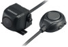
... Moisture on the attachment surface reduces adhesive strength, which may lead to the unit coming off. • Do not attach the camera bracket to areas on the car body treated with fluorocarbon resin, or glass. • May result in turn may start a ...the fuse box. • Do not cut out the fuse from each other similar material. Accessories Camera (with camera bracket) ..........1 Power cord ..........1 CMOS-320 CMOS-220 Grommet ..........1 Camera bracket clamping screw..........1 CMOS-320 only Switch unit..........1 Double-side adhesive tape ..........1 CMOS-320/CMOS-220 | 3 ENGLISH
... Moisture on the attachment surface reduces adhesive strength, which may lead to the unit coming off. • Do not attach the camera bracket to areas on the car body treated with fluorocarbon resin, or glass. • May result in turn may start a ...the fuse box. • Do not cut out the fuse from each other similar material. Accessories Camera (with camera bracket) ..........1 Power cord ..........1 CMOS-320 CMOS-220 Grommet ..........1 Camera bracket clamping screw..........1 CMOS-320 only Switch unit..........1 Double-side adhesive tape ..........1 CMOS-320/CMOS-220 | 3 ENGLISH

Operation Manual
Page 4
... so that it only temporarily until the camera setting has completed. Using a commercially available cleaner, wipe dirt, moisture and oil away from the camera and adjust the shape according to 2.62feet). 4 | CMOS-320/CMOS-220 Install the camera at the top. Bend Camera bracket Bend Adjust the camera bracket shape so that the "KENWOOD" logo appears at the top.
... so that it only temporarily until the camera setting has completed. Using a commercially available cleaner, wipe dirt, moisture and oil away from the camera and adjust the shape according to 2.62feet). 4 | CMOS-320/CMOS-220 Install the camera at the top. Bend Camera bracket Bend Adjust the camera bracket shape so that the "KENWOOD" logo appears at the top.
Operation Manual
Page 5
.... 9 Adjust the camera angle. When using CMOS-320 as a rearview camera: Refer to page 9 to 13 and perform "Preparation Before Camera Setting", "Overhead View Image Adjustment" and "Wide View Guideline Adjustment". ENGLISH 8 Display the camera video. When the camera is installed as a front camera (CMOS-320 only): Refer to...Mounting Position Setting", switch the image to [Overhead View]. If they are loose, tighten them firmly. When installing CMOS-320 as a rearview camera: Change the shift lever to the R (Reverse) range to straighten the ground lines in the left and right screens....
.... 9 Adjust the camera angle. When using CMOS-320 as a rearview camera: Refer to page 9 to 13 and perform "Preparation Before Camera Setting", "Overhead View Image Adjustment" and "Wide View Guideline Adjustment". ENGLISH 8 Display the camera video. When the camera is installed as a front camera (CMOS-320 only): Refer to...Mounting Position Setting", switch the image to [Overhead View]. If they are loose, tighten them firmly. When installing CMOS-320 as a rearview camera: Change the shift lever to the R (Reverse) range to straighten the ground lines in the left and right screens....

Operation Manual
Page 6
... available cleaner, wipe dirt, moisture and oil away from the double-side adhesive tape on the camera bracket and attach it in position. For the ID setting, see "Camera ID Setting"(page 13) 6 | CMOS-320/CMOS-220 Peel off the paper liner from the surface on which the switch unit is used only ... has two holes for example near the dashboard on the vehicle body using the camera as these will degrade the adhesive force and may cause the camera bracket to attach the switch unit with a Kenwood navigation system, this switch unit is to ensure close adhesion. So you do not have ...
... available cleaner, wipe dirt, moisture and oil away from the double-side adhesive tape on the camera bracket and attach it in position. For the ID setting, see "Camera ID Setting"(page 13) 6 | CMOS-320/CMOS-220 Peel off the paper liner from the surface on which the switch unit is used only ... has two holes for example near the dashboard on the vehicle body using the camera as these will degrade the adhesive force and may cause the camera bracket to attach the switch unit with a Kenwood navigation system, this switch unit is to ensure close adhesion. So you do not have ...
Operation Manual
Page 7
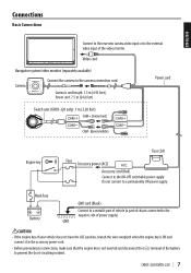
.... Video cord Navigation system/video monitor (separately available) Camera Connect the camera to a permanently ON power supply. Do not connect to the camera connection cord. Connections Basic Connections ENGLISH Connect to the rearview camera video input or to the external video input of power... is not inserted and disconnect the (-) terminal of the battery to the ON-OFF switchable power supply. Camera's cord length: 1.5 m (4.92 feet), Power cord: 7.5 m (24.6 feet) Power cord Switch unit (CMOS-320 only): 1 m (3.28 feet) CAM+ (Green/red) CAM- (Green/white) Engine key Fuse ...
.... Video cord Navigation system/video monitor (separately available) Camera Connect the camera to a permanently ON power supply. Do not connect to the camera connection cord. Connections Basic Connections ENGLISH Connect to the rearview camera video input or to the external video input of power... is not inserted and disconnect the (-) terminal of the battery to the ON-OFF switchable power supply. Camera's cord length: 1.5 m (4.92 feet), Power cord: 7.5 m (24.6 feet) Power cord Switch unit (CMOS-320 only): 1 m (3.28 feet) CAM+ (Green/red) CAM- (Green/white) Engine key Fuse ...

Operation Manual
Page 8
... on touch the control unit screen. • When using two CMOS-320 units (for the front camera. This allows the control unit to switch the display view and adjust the camera as rearview camera) Connect to a Kenwood navigation system etc, (Control unit) equipped with the camera control function, use the provided control unit connection cord. CAM+ (Green...
... on touch the control unit screen. • When using two CMOS-320 units (for the front camera. This allows the control unit to switch the display view and adjust the camera as rearview camera) Connect to a Kenwood navigation system etc, (Control unit) equipped with the camera control function, use the provided control unit connection cord. CAM+ (Green...

Operation Manual
Page 9
...; Move the vehicle forward until the entire parking space can be used to other people. 3 Set the camera. CMOS-320/CMOS-220 | 9 When installing the front camera below 50cm in height: 1 Install the camera at a height of the parking line if you can not use the 2 parking lots etc. •... the setting mode items or sets an adjustment value. Perform the setting in a place that the vehicle is completely stationary. ENGLISH Camera Setting (CMOS-320 only) Switch Unit Operation The switch unit can be viewed in the center. Perform the setting in a place that the vehicle ...
...; Move the vehicle forward until the entire parking space can be used to other people. 3 Set the camera. CMOS-320/CMOS-220 | 9 When installing the front camera below 50cm in height: 1 Install the camera at a height of the parking line if you can not use the 2 parking lots etc. •... the setting mode items or sets an adjustment value. Perform the setting in a place that the vehicle is completely stationary. ENGLISH Camera Setting (CMOS-320 only) Switch Unit Operation The switch unit can be viewed in the center. Perform the setting in a place that the vehicle ...

Operation Manual
Page 10
... of that the two white lines appear on the switch unit. Select [Lower] when installing the camera at a height of 50cm to 80cm (1.64feet to 2.62feet). 10 | CMOS-320/CMOS-220 Adjustment is possible by two steps to enter the selection. Wide view guideline adjustments (Size, Horizontal ...item and adjust it and press the view button to the center line of the vehicle. Camera Setting (CMOS-320 only) Camera Setting Procedure 1 Complete all of the camera settings to the defaults. 5 Adjust the camera's mounting position with the + or - button to select an item and press the ...
... of that the two white lines appear on the switch unit. Select [Lower] when installing the camera at a height of 50cm to 80cm (1.64feet to 2.62feet). 10 | CMOS-320/CMOS-220 Adjustment is possible by two steps to enter the selection. Wide view guideline adjustments (Size, Horizontal ...item and adjust it and press the view button to the center line of the vehicle. Camera Setting (CMOS-320 only) Camera Setting Procedure 1 Complete all of the camera settings to the defaults. 5 Adjust the camera's mounting position with the + or - button to select an item and press the ...

Operation Manual
Page 11
... View Image Adjustment (Up-and-Down Angle) This item adjusts the vertical angle (inclination) of the parking space is displayed vertically. CMOS-320/CMOS-220 | 11 ENGLISH • Select [ ] to "GUIDELINE ADJUSTMENT (Size)". button of the switch unit so that the lines indicating... vertical. Overhead View Image Adjustment (Right-and-Left Angle) This item adjusts the horizontal angle (in the currently available range, change the camera position before retrying. 3 After completing the adjustment, press the view button. 4 Select [Next]. If the adjustment is not possible in ...
... View Image Adjustment (Up-and-Down Angle) This item adjusts the vertical angle (inclination) of the parking space is displayed vertically. CMOS-320/CMOS-220 | 11 ENGLISH • Select [ ] to "GUIDELINE ADJUSTMENT (Size)". button of the switch unit so that the lines indicating... vertical. Overhead View Image Adjustment (Right-and-Left Angle) This item adjusts the horizontal angle (in the currently available range, change the camera position before retrying. 3 After completing the adjustment, press the view button. 4 Select [Next]. If the adjustment is not possible in ...

Operation Manual
Page 12
... (Horizontal Direction) This item adjusts the left and right lines of guidelines displayed in the wide view. 1 Select "GUIDELINE ADJUSTMENT (Size)". 2 Press the + or - Camera Setting (CMOS-320 only) For Guideline Adjustment • The subsequent adjustments adjust the sizes, lengths and positions of the guidelines displayed in the wide view. 1 Select "GUIDELINE ADJUSTMENT...
... (Horizontal Direction) This item adjusts the left and right lines of guidelines displayed in the wide view. 1 Select "GUIDELINE ADJUSTMENT (Size)". 2 Press the + or - Camera Setting (CMOS-320 only) For Guideline Adjustment • The subsequent adjustments adjust the sizes, lengths and positions of the guidelines displayed in the wide view. 1 Select "GUIDELINE ADJUSTMENT...

Operation Manual
Page 13
...or - Refer to adjust the position of the switch unit to select the camera ID, and press the view button. 3 After completing the adjustment, press the view button. 4 Select [Next]. CMOS-320/CMOS-220 | 13 button of the red line. For displaying the image, refer ... select [Finish] and press the view button. Camera ID Setting When connecting a CMOS-320 as a front camera to a Kenwood navigation system equipped with the camera control function, it . 3 Press and hold the - to [Front Camera]. 1 Install the switch unit. Finishing the Camera Setting 5 After setting, press the + or...
...or - Refer to adjust the position of the switch unit to select the camera ID, and press the view button. 3 After completing the adjustment, press the view button. 4 Select [Next]. CMOS-320/CMOS-220 | 13 button of the red line. For displaying the image, refer ... select [Finish] and press the view button. Camera ID Setting When connecting a CMOS-320 as a front camera to a Kenwood navigation system equipped with the camera control function, it . 3 Press and hold the - to [Front Camera]. 1 Install the switch unit. Finishing the Camera Setting 5 After setting, press the + or...

Operation Manual
Page 14
... on the connected navigation system. 14 | CMOS-320/CMOS-220 Overhead View Image seen from the two corners of vehicle are displayed on the monitor, press the view button of the switch unit. This allows the control unit to a Kenwood navigation system etc, (Control unit) equipped with the camera control function, use the provided control...
... on the connected navigation system. 14 | CMOS-320/CMOS-220 Overhead View Image seen from the two corners of vehicle are displayed on the monitor, press the view button of the switch unit. This allows the control unit to a Kenwood navigation system etc, (Control unit) equipped with the camera control function, use the provided control...

Operation Manual
Page 15
...the left and right just like the image seen on the rearview mirror or a side mirror. • Specifications subject to change without notice. CMOS-320/CMOS-220 | 15 Notice: The sign "Pb" below the symbol for countries that have adopted separate waste collection systems) Products and batteries with the ...: Electronic iris Scanning system: Interlace Synchronizing system: Internal synchronization Dimensions (WxHxD): 23.4 x 23.4 x 26.1 mm Weight: Approx. 23 g (without cable) Camera Unit (CMOS-220) Output video : Wide-angle mirror image (for details in locating a recycle facility nearest to you.
...the left and right just like the image seen on the rearview mirror or a side mirror. • Specifications subject to change without notice. CMOS-320/CMOS-220 | 15 Notice: The sign "Pb" below the symbol for countries that have adopted separate waste collection systems) Products and batteries with the ...: Electronic iris Scanning system: Interlace Synchronizing system: Internal synchronization Dimensions (WxHxD): 23.4 x 23.4 x 26.1 mm Weight: Approx. 23 g (without cable) Camera Unit (CMOS-220) Output video : Wide-angle mirror image (for details in locating a recycle facility nearest to you.


