
Operation Manual
Page 1
... on the product. Familiarity with installation and operation procedures will help you call upon your Kenwood product at www.Kenwoodusa.com © 2014 JVC KENWOOD Corporation LYT2720-001A (W) For your new Universal Camera. Refer to read through this instruction manual. Model CMOS-320/CMOS-220 Serial number US Residence Only Register Online Register your Kenwood dealer for information or service on the warranty card, and...
... on the product. Familiarity with installation and operation procedures will help you call upon your Kenwood product at www.Kenwoodusa.com © 2014 JVC KENWOOD Corporation LYT2720-001A (W) For your new Universal Camera. Refer to read through this instruction manual. Model CMOS-320/CMOS-220 Serial number US Residence Only Register Online Register your Kenwood dealer for information or service on the warranty card, and...

Operation Manual
Page 2
... make a hole to install the camera, check the location of pipes, tanks and wiring and avoid touching them. Do not use a hard cloth and/or a volatile substance such as it may cause your unit to malfunction. • Do not use your eyes. battery. 2 Make the proper input and output wire connections for each unit. 3 Connect the wiring harness wires in the following order: ground, ignition and camera unit. 4 Install the unit...
... make a hole to install the camera, check the location of pipes, tanks and wiring and avoid touching them. Do not use a hard cloth and/or a volatile substance such as it may cause your unit to malfunction. • Do not use your eyes. battery. 2 Make the proper input and output wire connections for each unit. 3 Connect the wiring harness wires in the following order: ground, ignition and camera unit. 4 Install the unit...

Operation Manual
Page 3
... replace the old fuse with one with the same rating. • Insulate unconnected wires with vinyl tape or other units, then make connections correctly. • Secure the wiring with camera bracket) ..........1 Power cord ..........1 CMOS-320 CMOS-220 Grommet ..........1 Camera bracket clamping screw..........1 CMOS-320 only Switch unit..........1 Double-side adhesive tape ..........1 CMOS-320/CMOS-220 | 3 ENGLISH on the car are working properly. • Install so that it does not obstruct the rear field...
... replace the old fuse with one with the same rating. • Insulate unconnected wires with vinyl tape or other units, then make connections correctly. • Secure the wiring with camera bracket) ..........1 Power cord ..........1 CMOS-320 CMOS-220 Grommet ..........1 Camera bracket clamping screw..........1 CMOS-320 only Switch unit..........1 Double-side adhesive tape ..........1 CMOS-320/CMOS-220 | 3 ENGLISH on the car are working properly. • Install so that it does not obstruct the rear field...

Operation Manual
Page 4
... the top. Mount so that it only temporarily until the camera setting has completed. Bend Camera bracket Bend Adjust the camera bracket shape so that the "KENWOOD" logo appears at the top. 6 Fix the camera temporarily with tape, etc. The CMOS-320 should be hindered depending on the rear of the vehicle Installation position Installing the Camera/Adjusting its angle...
... the top. Mount so that it only temporarily until the camera setting has completed. Bend Camera bracket Bend Adjust the camera bracket shape so that the "KENWOOD" logo appears at the top. 6 Fix the camera temporarily with tape, etc. The CMOS-320 should be hindered depending on the rear of the vehicle Installation position Installing the Camera/Adjusting its angle...
Operation Manual
Page 5
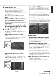
... to [Overhead View]. Vehicle rear part or bumper When installing CMOS-320 as a rearview camera: Refer to page 9 to 13 and perform "Preparation Before Camera Setting" and "Overhead View Image Adjustment". When you select [Lower] for "Mounting Position Setting", switch the image to , and display the image of the front of the unit that you have connected this camera to [Overhead View] (page 14) and adjust the camera...
... to [Overhead View]. Vehicle rear part or bumper When installing CMOS-320 as a rearview camera: Refer to page 9 to 13 and perform "Preparation Before Camera Setting" and "Overhead View Image Adjustment". When you select [Lower] for "Mounting Position Setting", switch the image to , and display the image of the front of the unit that you have connected this camera to [Overhead View] (page 14) and adjust the camera...

Operation Manual
Page 6
... x 8mm) Installing the Switch Unit (CMOS-320 only) 1 Clean the switch unit installation surface. If required, secure the bracket on the driver seat side. ɹɹɹ When using the camera bracket clamping screw. After attaching, push the camera bracket with double-side adhesive tape. So you do not have to fit the position of the CMOS-320 unit. For the ID setting, see...
... x 8mm) Installing the Switch Unit (CMOS-320 only) 1 Clean the switch unit installation surface. If required, secure the bracket on the driver seat side. ɹɹɹ When using the camera bracket clamping screw. After attaching, push the camera bracket with double-side adhesive tape. So you do not have to fit the position of the CMOS-320 unit. For the ID setting, see...
Operation Manual
Page 7
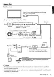
... connections, make sure that the engine key is not inserted and disconnect the (-) terminal of the battery to the external video input of chassis connected to the camera connection cord. CMOS-320/CMOS-220 | 7 Connections Basic Connections ENGLISH Connect to the rearview camera video input or to prevent the short-circuiting incident. Do not connect to the ON-OFF switchable power supply. Camera's cord length: 1.5 m (4.92 feet), Power cord: 7.5 m (24.6 feet) Power cord Switch unit (CMOS-320...
... connections, make sure that the engine key is not inserted and disconnect the (-) terminal of the battery to the external video input of chassis connected to the camera connection cord. CMOS-320/CMOS-220 | 7 Connections Basic Connections ENGLISH Connect to the rearview camera video input or to prevent the short-circuiting incident. Do not connect to the ON-OFF switchable power supply. Camera's cord length: 1.5 m (4.92 feet), Power cord: 7.5 m (24.6 feet) Power cord Switch unit (CMOS-320...

Operation Manual
Page 8
... control unit to switch the display view and adjust the camera as "Basic Connections". • The provided switch unit is required to the external video input. Video cord To power supply 8 | CMOS-320/CMOS-220 For details, see "Camera ID Setting" (page 13). • Connect the power supply in the same way as well on touch the control unit screen. • When using two CMOS-320 units (for the front and rear), it is not used in the system connection. Select...
... control unit to switch the display view and adjust the camera as "Basic Connections". • The provided switch unit is required to the external video input. Video cord To power supply 8 | CMOS-320/CMOS-220 For details, see "Camera ID Setting" (page 13). • Connect the power supply in the same way as well on touch the control unit screen. • When using two CMOS-320 units (for the front and rear), it is not used in the system connection. Select...

Operation Manual
Page 9
... camera: 1 Stop the vehicle. CMOS-320/CMOS-220 | 9 ENGLISH Camera Setting (CMOS-320 only) Switch Unit Operation The switch unit can be symmetric in the "Corner View". 2 Move the vehicle on the center of the parking line. • You can use the 2 parking lots etc. • Be sure to switch the image display mode, view/hide the guideline display and adjust the camera. Perform the setting in a place that will...
... camera: 1 Stop the vehicle. CMOS-320/CMOS-220 | 9 ENGLISH Camera Setting (CMOS-320 only) Switch Unit Operation The switch unit can be symmetric in the "Corner View". 2 Move the vehicle on the center of the parking line. • You can use the 2 parking lots etc. • Be sure to switch the image display mode, view/hide the guideline display and adjust the camera. Perform the setting in a place that will...

Operation Manual
Page 10
... turns from blue to yellow. Camera Setting (CMOS-320 only) Camera Setting Procedure 1 Complete all of the camera settings to the defaults. 5 Adjust the camera's mounting position with the + or - The following items are available for your video monitor. 3 Press and hold the view and + buttons of the switch unit simultaneously to enter the camera adjustment mode. 4 First select the positioning of the camera installation position. 1 Select "OVERHEAD VIEW IMAGE ADJUSTMENT...
... turns from blue to yellow. Camera Setting (CMOS-320 only) Camera Setting Procedure 1 Complete all of the camera settings to the defaults. 5 Adjust the camera's mounting position with the + or - The following items are available for your video monitor. 3 Press and hold the view and + buttons of the switch unit simultaneously to enter the camera adjustment mode. 4 First select the positioning of the camera installation position. 1 Select "OVERHEAD VIEW IMAGE ADJUSTMENT...

Operation Manual
Page 11
... switch unit so that the lines indicating the vehicle width are shown vertical. Advances to "OVERHEAD VIEW IMAGE ADJUSTMENT (Right-and-Left ANGLE)". Advances to "OVERHEAD VIEW IMAGE ADJUSTMENT (Up-and-Down ANGLE)". Adjustment is not possible in the currently available range, change the camera position before retrying. 3 After completing the adjustment, press the view button. 4 Select [Next]. CMOS-320/CMOS-220 | 11 If the adjustment...
... switch unit so that the lines indicating the vehicle width are shown vertical. Advances to "OVERHEAD VIEW IMAGE ADJUSTMENT (Right-and-Left ANGLE)". Advances to "OVERHEAD VIEW IMAGE ADJUSTMENT (Up-and-Down ANGLE)". Adjustment is not possible in the currently available range, change the camera position before retrying. 3 After completing the adjustment, press the view button. 4 Select [Next]. CMOS-320/CMOS-220 | 11 If the adjustment...

Operation Manual
Page 12
... displayed in the wide view and overhead view. Advances to "GUIDELINE ADJUSTMENT (Red Line Position Setting)". 12 | CMOS-320/CMOS-220 button of the guidelines displayed in the wide view. 1 Select "GUIDELINE ADJUSTMENT (Size)". 2 Press the + or - Advances to "GUIDELINE ADJUSTMENT (Horizontal direction)". Camera Setting (CMOS-320 only) For Guideline Adjustment • The subsequent adjustments adjust the sizes, lengths and positions of the switch unit to adjust the size. 3 After completing the adjustment, press the view button...
... displayed in the wide view and overhead view. Advances to "GUIDELINE ADJUSTMENT (Red Line Position Setting)". 12 | CMOS-320/CMOS-220 button of the guidelines displayed in the wide view. 1 Select "GUIDELINE ADJUSTMENT (Size)". 2 Press the + or - Advances to "GUIDELINE ADJUSTMENT (Horizontal direction)". Camera Setting (CMOS-320 only) For Guideline Adjustment • The subsequent adjustments adjust the sizes, lengths and positions of the switch unit to adjust the size. 3 After completing the adjustment, press the view button...

Operation Manual
Page 13
... the view button. For displaying the image, refer to the instruction manual of it is required to assign the ID to set the reference line for the vehicle parking position. 1 Select "GUIDELINE ADJUSTMENT (Red Line Position Setting)". 2 Press the + or - button of the red line. If the edge of your vehicle's bumper cannot be used independently to [Front Camera]. 1 Install the switch unit. button for...
... the view button. For displaying the image, refer to the instruction manual of it is required to assign the ID to set the reference line for the vehicle parking position. 1 Select "GUIDELINE ADJUSTMENT (Red Line Position Setting)". 2 Press the + or - button of the red line. If the edge of your vehicle's bumper cannot be used independently to [Front Camera]. 1 Install the switch unit. button for...

Operation Manual
Page 14
... on the camera installation position, the Overhead View image may not be displayed correctly. • Overhead View may appear twice, depending on touch the control unit screen (page 8). Wide View Camera image covering a horizontal angle of about 195°. This allows the control unit to a Kenwood navigation system etc, (Control unit) equipped with the camera control function, use the provided control unit connection cord. Each press switches the image display mode in the...
... on the camera installation position, the Overhead View image may not be displayed correctly. • Overhead View may appear twice, depending on touch the control unit screen (page 8). Wide View Camera image covering a horizontal angle of about 195°. This allows the control unit to a Kenwood navigation system etc, (Control unit) equipped with the camera control function, use the provided control unit connection cord. Each press switches the image display mode in the...

Operation Manual
Page 15
... sign "Pb" below the symbol for details in locating a recycle facility nearest to you. Old electrical and electronic equipment and batteries should be disposed as household waste. CMOS-320/CMOS-220 | 15 ENGLISH Specifications Camnit (CMOS-320) Output video : Wide-angle mirror image (for rearview)/wideangle normal image (for front view) Sensor: 1/3.6-inch color CMOS sensor Number of pixels: Approx. 330,000 pixels Lens...
... sign "Pb" below the symbol for details in locating a recycle facility nearest to you. Old electrical and electronic equipment and batteries should be disposed as household waste. CMOS-320/CMOS-220 | 15 ENGLISH Specifications Camnit (CMOS-320) Output video : Wide-angle mirror image (for rearview)/wideangle normal image (for front view) Sensor: 1/3.6-inch color CMOS sensor Number of pixels: Approx. 330,000 pixels Lens...
Operation Manual
Page 59
... harmful interference to radio or television reception, which the receiver is connected. • Consult the dealer or an experienced radio/TV technician for a Class B digital device, pursuant to radio communications, if it is not installed and used in the instruction manual. These limits are expressly approved in accordance with the limits for help. For Turkey Bu ürün 28300 sayılı...
... harmful interference to radio or television reception, which the receiver is connected. • Consult the dealer or an experienced radio/TV technician for a Class B digital device, pursuant to radio communications, if it is not installed and used in the instruction manual. These limits are expressly approved in accordance with the limits for help. For Turkey Bu ürün 28300 sayılı...


