Instruction Manual
Page 1
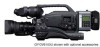
... this JVC product. which is located on the body. DV CAMCORDER GY-DV5100 INTRODUCTION CONTROLS, INDICATORS AND CONNECTORS BASIC SYSTEM CONNECTIONS AND ADJUSTMENTS POWER SUPPLY PREPARATIONS SETTING AND ADJUSTMENTS BEFORE SHOOTING SHOOTING OPERATION INSTRUCTIONS PLAYBACK MODE USING EXTERNAL COMPONENTS TIME CODE OPERATION MENU SCREENS FEATURES OF THE CAMERA SECTION OTHERS * The illustration shows the GY-DV5100 DV Camcorder with...
... this JVC product. which is located on the body. DV CAMCORDER GY-DV5100 INTRODUCTION CONTROLS, INDICATORS AND CONNECTORS BASIC SYSTEM CONNECTIONS AND ADJUSTMENTS POWER SUPPLY PREPARATIONS SETTING AND ADJUSTMENTS BEFORE SHOOTING SHOOTING OPERATION INSTRUCTIONS PLAYBACK MODE USING EXTERNAL COMPONENTS TIME CODE OPERATION MENU SCREENS FEATURES OF THE CAMERA SECTION OTHERS * The illustration shows the GY-DV5100 DV Camcorder with...
Instruction Manual
Page 4
...GY-DV5100U. This unit is a registered trademark of Sony Corporation. ● Compact, lightweight design Employment of video or audio due to 2084.6 Hz. ● DV (i. The following phenomena may occur when tapes recorded on other units (including another GY-DV5100) are recorded or played back on this camcorder...). Switch provided for high-quality picture 1/2" 3-CCD with almost no illumination. Thank you move between...copyright holders. ● JVC cannot assume liabilities that both standard-size DV videocassettes and mini-size DV videocassettes Recording/playback can ...
...GY-DV5100U. This unit is a registered trademark of Sony Corporation. ● Compact, lightweight design Employment of video or audio due to 2084.6 Hz. ● DV (i. The following phenomena may occur when tapes recorded on other units (including another GY-DV5100) are recorded or played back on this camcorder...). Switch provided for high-quality picture 1/2" 3-CCD with almost no illumination. Thank you move between...copyright holders. ● JVC cannot assume liabilities that both standard-size DV videocassettes and mini-size DV videocassettes Recording/playback can ...
Instruction Manual
Page 7
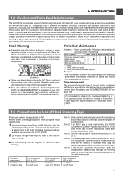
... cleaning tape case contains instructions for use head cleaning tapes other than four times at your nearest JVC-authorized service agent. 1-3 Precautions for Use of professional video equipment at the most for periodical head cleaning. To prevent wear and deterioration, clean the ... unit is also recommended to apply periodical maintenance (inspection) to the running time). INTRODUCTION 1-2 Routine and Periodical Maintenance The GY-DV5100 incorporates precision mechanical parts, which shows the accumulated drum running time. Do not use of failure. The tape runs for ...
... cleaning tape case contains instructions for use head cleaning tapes other than four times at your nearest JVC-authorized service agent. 1-3 Precautions for Use of professional video equipment at the most for periodical head cleaning. To prevent wear and deterioration, clean the ... unit is also recommended to apply periodical maintenance (inspection) to the running time). INTRODUCTION 1-2 Routine and Periodical Maintenance The GY-DV5100 incorporates precision mechanical parts, which shows the accumulated drum running time. Do not use of failure. The tape runs for ...

Instruction Manual
Page 8
...distortions and deformations of the tape edges. 1-5 Battery Pack to be Used ● Use JVC's videocassette tapes marked with a switch on the back to prevent accidental erasure. ● ... Hourly temperature change Less than 10°C - - INTRODUCTION 1-4 Videocassette to be Used The GY-DV5100 can use any of the following instructions for the best recording and ● Do not leave... may damage the tape. If videotapes are not in the environment below. Standard DV videocassette: LA-DV276, LA-DV186, LADV124 Mini DV videocassette: M-DV63PRO, M-DV60, M-DV30 * Do not use , store them ...
...distortions and deformations of the tape edges. 1-5 Battery Pack to be Used ● Use JVC's videocassette tapes marked with a switch on the back to prevent accidental erasure. ● ... Hourly temperature change Less than 10°C - - INTRODUCTION 1-4 Videocassette to be Used The GY-DV5100 can use any of the following instructions for the best recording and ● Do not leave... may damage the tape. If videotapes are not in the environment below. Standard DV videocassette: LA-DV276, LA-DV186, LADV124 Mini DV videocassette: M-DV63PRO, M-DV60, M-DV30 * Do not use , store them ...

Instruction Manual
Page 19
.... 1 2 4 3 No. CONTROLS, INDICATORS AND CONNECTORS 2-5 Rear Section t y u PHONES DV INT DC OUT DC IN TALLY CH-1 CH-2 REAR AUDIO IN q re w 1 [TALLY] Tally lamp This lamp lights up when the GY-DV5100 enters the record mode. The sound from this connector, set with the AUDIO SELECT item... on the AUDIO/VIDEO menu screen and MONITOR SELECT switch C on page 16. To record the DV signal from the monitoring speaker is interrupted when...
.... 1 2 4 3 No. CONTROLS, INDICATORS AND CONNECTORS 2-5 Rear Section t y u PHONES DV INT DC OUT DC IN TALLY CH-1 CH-2 REAR AUDIO IN q re w 1 [TALLY] Tally lamp This lamp lights up when the GY-DV5100 enters the record mode. The sound from this connector, set with the AUDIO SELECT item... on the AUDIO/VIDEO menu screen and MONITOR SELECT switch C on page 16. To record the DV signal from the monitoring speaker is interrupted when...
Instruction Manual
Page 31
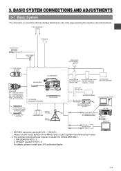
PROTEC) 1.5" VIEW FINDER VF-P115B VF-P116 DV CAMCORDER ZOOM LENS S14 × 7.3B12U(FUJINON) S17 × 6.6BRM(FUJINON)...BRIGHT FRONT REAR CH-1 CH-2 AUDIO IN AUDIO SELECT CH-1 CH-2 AUTO MANUAL DISPLAY PULL OPEN GY-DV5100 STANDARD PACKAGE TRIPOD BASE FOCUS MANUAL UNIT *1 HZ-FM13 (FUJINON) HZ-FM15 (CANON) ZOOM ... individual attachments, refer to attach the SHOULDER BELT. 1. SPACER (SC46311-001) × 2 For details, please consult your JVC authorized dealer. 31 BASIC SYSTEM CONNECTIONS AND ADJUSTMENTS 3-1 Basic System * For information on connection with S14 × 7.3B12/U....
PROTEC) 1.5" VIEW FINDER VF-P115B VF-P116 DV CAMCORDER ZOOM LENS S14 × 7.3B12U(FUJINON) S17 × 6.6BRM(FUJINON)...BRIGHT FRONT REAR CH-1 CH-2 AUDIO IN AUDIO SELECT CH-1 CH-2 AUTO MANUAL DISPLAY PULL OPEN GY-DV5100 STANDARD PACKAGE TRIPOD BASE FOCUS MANUAL UNIT *1 HZ-FM13 (FUJINON) HZ-FM15 (CANON) ZOOM ... individual attachments, refer to attach the SHOULDER BELT. 1. SPACER (SC46311-001) × 2 For details, please consult your JVC authorized dealer. 31 BASIC SYSTEM CONNECTIONS AND ADJUSTMENTS 3-1 Basic System * For information on connection with S14 × 7.3B12/U....

Instruction Manual
Page 32
...the removed cap on the camera the viewfinder can be observed with the shoe. 4. Tighten the stopper screw. 5. CAUTION: ● Set the GY-DV5100's power switch to tighten the mount ring completely. Loosen the mount ring. 2. Connect the cable connector. 3. CAUTION: ● Be sure to ...Change the mounting position of the viewfinder mount base with the hole in the lens dropping off or disturbed back focus. ● Set the GY-DV5100's power switch to remove the viewfinder. ■ Sliding the viewfinder forward 1. BASIC SYSTEM CONNECTIONS AND ADJUSTMENTS 3-2 Attaching the Zoom Lens Pin...
...the removed cap on the camera the viewfinder can be observed with the shoe. 4. Tighten the stopper screw. 5. CAUTION: ● Set the GY-DV5100's power switch to tighten the mount ring completely. Loosen the mount ring. 2. Connect the cable connector. 3. CAUTION: ● Be sure to ...Change the mounting position of the viewfinder mount base with the hole in the lens dropping off or disturbed back focus. ● Set the GY-DV5100's power switch to remove the viewfinder. ■ Sliding the viewfinder forward 1. BASIC SYSTEM CONNECTIONS AND ADJUSTMENTS 3-2 Attaching the Zoom Lens Pin...
Instruction Manual
Page 35
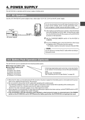
...connect the DC cable while recording is being performed. 4-2 Battery Pack Operation (Optional) The GY-DV5100 can be operated with the following symptoms may occur if the DC cable is connected or ...JVC AA-P250 AC power adapter (max. Audio signal are set to the DC IN connector of the AA-P250. Battery case: SCV2978-002 See "Attaching the NP-1B type Battery" on the GY-DV5100...DV INT DC OUT DC IN TALLY CH-1 CH-2 REAR AUDIO IN Do not use any power source with large fluctuations in the illustration. 2. It is supplied to CAMERA. 3. Remove the battery pack when the GY-DV5100...
...connect the DC cable while recording is being performed. 4-2 Battery Pack Operation (Optional) The GY-DV5100 can be operated with the following symptoms may occur if the DC cable is connected or ...JVC AA-P250 AC power adapter (max. Audio signal are set to the DC IN connector of the AA-P250. Battery case: SCV2978-002 See "Attaching the NP-1B type Battery" on the GY-DV5100...DV INT DC OUT DC IN TALLY CH-1 CH-2 REAR AUDIO IN Do not use any power source with large fluctuations in the illustration. 2. It is supplied to CAMERA. 3. Remove the battery pack when the GY-DV5100...
Instruction Manual
Page 38
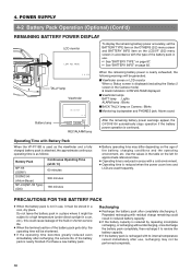
... lamp : Blinks ■ BACK TALLY lamp on Camera : Blinks ■ Monitoring loudspeaker and PHONES jack: Alarm sound After the remaining battery power warnings appear, the GY-DV5100 automatically stops operation if the battery power operation is reduced in a car, etc.), this could result in a cool, dry place. OPEN CH-1 AUDIO LEVEL CH...
... lamp : Blinks ■ BACK TALLY lamp on Camera : Blinks ■ Monitoring loudspeaker and PHONES jack: Alarm sound After the remaining battery power warnings appear, the GY-DV5100 automatically stops operation if the battery power operation is reduced in a car, etc.), this could result in a cool, dry place. OPEN CH-1 AUDIO LEVEL CH...
Instruction Manual
Page 39
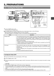
...the LCD monitor or in the viewfinder or on in the record-standby or STOP mode. 2. Place the GY-DV5100 in accordance with the selected mode. Should the POWER switch accidentally be used for a longer period.) CAUTION...the STBY or STOP indication is turned off. When the MODE switch is pressed upward, the mode is loaded, the GY-DV5100 enters the stop mode. PREPARATIONS 5-1 Turning the Power ON EDITSEARCH FILTER 1 3200K 2 5600K 1/8 ND .3 5600K ... to ON. Set the POWER switch to indicate STOP. DV input is loaded, the GY-DV5100 enters the record-standby mode automatically.
...the LCD monitor or in the viewfinder or on in the record-standby or STOP mode. 2. Place the GY-DV5100 in accordance with the selected mode. Should the POWER switch accidentally be used for a longer period.) CAUTION...the STBY or STOP indication is turned off. When the MODE switch is pressed upward, the mode is loaded, the GY-DV5100 enters the stop mode. PREPARATIONS 5-1 Turning the Power ON EDITSEARCH FILTER 1 3200K 2 5600K 1/8 ND .3 5600K ... to ON. Set the POWER switch to indicate STOP. DV input is loaded, the GY-DV5100 enters the record-standby mode automatically.

Instruction Manual
Page 40
...Recording can start recording or before it in all the way in while the cassette is loaded differs with the mode of the GY-DV5100 (Camera mode or VTR mode) and the condition of the cassette back and insert the cassette tape straight into the cassette slot...; Insert a standard DV videocassette along the cassette insertion slot by pushing it enters the STOP mode. 40 Loading the Cassette 1. PREPARATIONS 5-2 Cassette Loading and Unloading OPEN knob Cassette cover Cassette insertion slot Cassette cover ● A cassette cannot be loaded or unloaded while the GY-DV5100 is closed, it ...
...Recording can start recording or before it in all the way in while the cassette is loaded differs with the mode of the GY-DV5100 (Camera mode or VTR mode) and the condition of the cassette back and insert the cassette tape straight into the cassette slot...; Insert a standard DV videocassette along the cassette insertion slot by pushing it enters the STOP mode. 40 Loading the Cassette 1. PREPARATIONS 5-2 Cassette Loading and Unloading OPEN knob Cassette cover Cassette insertion slot Cassette cover ● A cassette cannot be loaded or unloaded while the GY-DV5100 is closed, it ...

Instruction Manual
Page 46
...GY-DV5100 and an AC outlet or mount a charged battery on the GY-DV5100 to "OFF" or "ON" (charging takes places with the POWER switch set to charge AC outlet AA-P250 AC power adapter DC cable PHONES DV... INT DC OUT DC IN TALLY CH-1 CH-2 REAR AUDIO IN 1. However, it is possible to a power supply, but the date and time and time code data cannot be fully discharged when the GY-DV5100...not used for about three months, in battery is discharged but it gradually discharges while the GY-DV5100 is disconnected from a power supply. Leave the equipment in this case, recharge the built-in...
...GY-DV5100 and an AC outlet or mount a charged battery on the GY-DV5100 to "OFF" or "ON" (charging takes places with the POWER switch set to charge AC outlet AA-P250 AC power adapter DC cable PHONES DV... INT DC OUT DC IN TALLY CH-1 CH-2 REAR AUDIO IN 1. However, it is possible to a power supply, but the date and time and time code data cannot be fully discharged when the GY-DV5100...not used for about three months, in battery is discharged but it gradually discharges while the GY-DV5100 is disconnected from a power supply. Leave the equipment in this case, recharge the built-in...

Instruction Manual
Page 48
... video monitor and adjust the colors, contrast and brightness. 1. Brightness and contrast adjustment When the ambient brightness changes, etc., the brightness and contrast of the GY-DV5100. 2. 6. SETTING AND ADJUSTMENTS BEFORE SHOOTING 6-3 Viewfinder Adjustment 2. 1. Connect a color video monitor to adjust so that there is no difference in step 4. 7. Adjust the CHROMA control...
... video monitor and adjust the colors, contrast and brightness. 1. Brightness and contrast adjustment When the ambient brightness changes, etc., the brightness and contrast of the GY-DV5100. 2. 6. SETTING AND ADJUSTMENTS BEFORE SHOOTING 6-3 Viewfinder Adjustment 2. 1. Connect a color video monitor to adjust so that there is no difference in step 4. 7. Adjust the CHROMA control...
Instruction Manual
Page 51
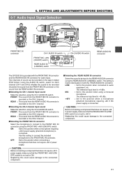
PRST FREE REC REGEN PHONES DV INT DC OUT DC IN TALLY CH-1 CH-2 REAR AUDIO IN REAR AUDIO IN connector The GY-DV5100 is made individually for both the REAR AUDIO IN connector. FRONT : The sound from the FRONT MIC IN connector is recorded on the CH-1 channel. ...
PRST FREE REC REGEN PHONES DV INT DC OUT DC IN TALLY CH-1 CH-2 REAR AUDIO IN REAR AUDIO IN connector The GY-DV5100 is made individually for both the REAR AUDIO IN connector. FRONT : The sound from the FRONT MIC IN connector is recorded on the CH-1 channel. ...
Instruction Manual
Page 54
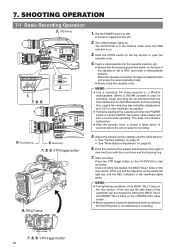
... SELECT CH-1 CH-2 AUTO MANUAL DISPLAY PULL OPEN POWER VTR ON OFF 1. 7. 8. 9. TALLY lamp 1. Slide the OPEN switch on the GY-DV5100 to start recording. MODE VTR CAM 2. 6. VTR trigger button 8. Start recording. Press the VTR trigger button on the top section to ON....conditions of the BACK TALLY lamp on the rear section of the cassette is recording. Zoom ring 7. 8. 9. MEMO: ● Use a standard DV videocassette or a MiniDV videocassette. (When a DVCAM cassette is used for recording. 5. VTR trigger button 54 Adjust the camera section settings and the ...
... SELECT CH-1 CH-2 AUTO MANUAL DISPLAY PULL OPEN POWER VTR ON OFF 1. 7. 8. 9. TALLY lamp 1. Slide the OPEN switch on the GY-DV5100 to start recording. MODE VTR CAM 2. 6. VTR trigger button 8. Start recording. Press the VTR trigger button on the top section to ON....conditions of the BACK TALLY lamp on the rear section of the cassette is recording. Zoom ring 7. 8. 9. MEMO: ● Use a standard DV videocassette or a MiniDV videocassette. (When a DVCAM cassette is used for recording. 5. VTR trigger button 54 Adjust the camera section settings and the ...

Instruction Manual
Page 55
...minutes, the mode switches to the tape protect mode. ☞ See "LONG PAUSE TIME item on the OTHERS (1/2) menu screen" on the GY-DV5100 or lens. 10.Ending recording: Press the VTR trigger button to confirm the recording is changed abruptly during recording. About the QUICK REC START ...Mode If the VTR trigger button is pressed, the viewfinder REC indicator lamp may blink and the GY-DV5100 may also occur.) 7.8. SHOOTING OPERATION REC BATT ALARM 7.8 8. To restart recording: Press the VTR trigger button on page 86. ● If...
...minutes, the mode switches to the tape protect mode. ☞ See "LONG PAUSE TIME item on the OTHERS (1/2) menu screen" on the GY-DV5100 or lens. 10.Ending recording: Press the VTR trigger button to confirm the recording is changed abruptly during recording. About the QUICK REC START ...Mode If the VTR trigger button is pressed, the viewfinder REC indicator lamp may blink and the GY-DV5100 may also occur.) 7.8. SHOOTING OPERATION REC BATT ALARM 7.8 8. To restart recording: Press the VTR trigger button on page 86. ● If...

Instruction Manual
Page 57
...VTR mode indication 7-4 Checking Recorded Contents in Record-Standby Mode (Recording Check Function) RET button This function is available only when the GY-DV5100 is engaged from the tape protect mode, press the VTR trigger button. ● The drum starts rotating, and recording starts after playback...image from the tape protect mode, press the RET button. The camera will automatically return to recording mode after about 5 minutes, the GY-DV5100 automatically stops drum rotation in the standby mode. is shown on the camera lens section. • The tape is rewound and played...
...VTR mode indication 7-4 Checking Recorded Contents in Record-Standby Mode (Recording Check Function) RET button This function is available only when the GY-DV5100 is engaged from the tape protect mode, press the VTR trigger button. ● The drum starts rotating, and recording starts after playback...image from the tape protect mode, press the RET button. The camera will automatically return to recording mode after about 5 minutes, the GY-DV5100 automatically stops drum rotation in the standby mode. is shown on the camera lens section. • The tape is rewound and played...
Instruction Manual
Page 61
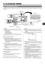
... BLANK SEARCH REW STOP FF PLAY STILL MODE VTR CAM Still button PLAY button STOP button POWER switch MODE switch MEMO: ● The GY-DV5100 can be viewed in the viewfinder, or on the LCD monitor, or on another unit, digital noise may appear during playback. ●... STOP button is selected on the screen. Load the recorded videocassette correctly. Open the operation cover on the top section of videocassettes: • DV videocassette • MiniDV videocassette • DVCAM videocassette ● Tapes recorded in the viewfinder or through the video output connector. ● The ...
... BLANK SEARCH REW STOP FF PLAY STILL MODE VTR CAM Still button PLAY button STOP button POWER switch MODE switch MEMO: ● The GY-DV5100 can be viewed in the viewfinder, or on the LCD monitor, or on another unit, digital noise may appear during playback. ●... STOP button is selected on the screen. Load the recorded videocassette correctly. Open the operation cover on the top section of videocassettes: • DV videocassette • MiniDV videocassette • DVCAM videocassette ● Tapes recorded in the viewfinder or through the video output connector. ● The ...

Instruction Manual
Page 64
...VIDEO menu, and then press the SHUTTER dial. ● The AUDIO/VIDEO menu screen appears. 3. When the SHUTTER dial is confirmed. 6. The GY-DV5100 records audio on CH-3 and CH-4) simultaneously. TC/UB/CLOCK.. TEST TONE ON AUDIO MODE 32K A.OUT AT SEARCH ON CH1 FRONT VR ENABLE ... Rotate the SHUTTER dial to display the TOP MENU screen. 2. LCD/VF.. VTR indicator Setting ■ Confirm that the GY-DV5100 is in the case of DV input.) When the GY-DV5100 is employed. Rotate the SHUTTER to 4 channels when the 12-bit, 32 kHz sampling frequency is used for 1 second or...
...VIDEO menu, and then press the SHUTTER dial. ● The AUDIO/VIDEO menu screen appears. 3. When the SHUTTER dial is confirmed. 6. The GY-DV5100 records audio on CH-3 and CH-4) simultaneously. TC/UB/CLOCK.. TEST TONE ON AUDIO MODE 32K A.OUT AT SEARCH ON CH1 FRONT VR ENABLE ... Rotate the SHUTTER dial to display the TOP MENU screen. 2. LCD/VF.. VTR indicator Setting ■ Confirm that the GY-DV5100 is in the case of DV input.) When the GY-DV5100 is employed. Rotate the SHUTTER to 4 channels when the 12-bit, 32 kHz sampling frequency is used for 1 second or...
Instruction Manual
Page 65
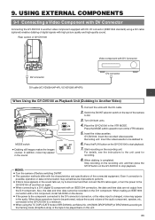
...VTR MODE. When making an IEEE1394 connection with DV Connector DV connector When Using the GY-DV5100 as Playback Unit (Dubbing to . USING EXTERNAL COMPONENTS 9-1 Connecting a Video Component with DV Connector Connecting the GY-DV5100 to another video component equipped with DV I/O connector (IEEE1394 standard) using the TC ...operations have to be performed, reduce the sound volume of the audio component, speaker, etc., connected to the GY-DV5100 to a minimum. ● When using a DV cable (optional) enables dubbing of the tape to be impossible to perform. ● If block noise appears ...
...VTR MODE. When making an IEEE1394 connection with DV Connector DV connector When Using the GY-DV5100 as Playback Unit (Dubbing to . USING EXTERNAL COMPONENTS 9-1 Connecting a Video Component with DV Connector Connecting the GY-DV5100 to another video component equipped with DV I/O connector (IEEE1394 standard) using the TC ...operations have to be performed, reduce the sound volume of the audio component, speaker, etc., connected to the GY-DV5100 to a minimum. ● When using a DV cable (optional) enables dubbing of the tape to be impossible to perform. ● If block noise appears ...


