
GY-DV500 User Manual - PDF (4,089KB)
Page 1
...JVC product. Retain this information for purchasing this unit, please read the instructions carefully to ensure the best possible performance. SC96874-003 For Customer Use : Enter below the Serial No. which is made from 100% recycled paper. Model No. Thank you for future reference. GY-DV500... Serial No. This instruction manual is located on the body. DV CAMCORDER GY-DV500 INTRODUCTION CONTROLS, INDICATORS AND CONNECTORS BASIC SYSTEM CONNECTIONS AND ADJUSTMENTS POWER SUPPLY PREPARATIONS SETTING AND ADJUSTMENTS BEFORE SHOOTING...
...JVC product. Retain this information for purchasing this unit, please read the instructions carefully to ensure the best possible performance. SC96874-003 For Customer Use : Enter below the Serial No. which is made from 100% recycled paper. Model No. Thank you for future reference. GY-DV500... Serial No. This instruction manual is located on the body. DV CAMCORDER GY-DV500 INTRODUCTION CONTROLS, INDICATORS AND CONNECTORS BASIC SYSTEM CONNECTIONS AND ADJUSTMENTS POWER SUPPLY PREPARATIONS SETTING AND ADJUSTMENTS BEFORE SHOOTING...
GY-DV500 User Manual - PDF (4,089KB)
Page 7
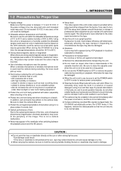
... INTRODUCTION 1-2 Precautions for Proper Use ● Supply voltage Make sure that the unit returns to hold the carrying handle. When storing the GY-DV500 for a long time, the storage temperatures should ...JVC-authorized service agent. This is never attached to strong vibrations or on the tape. ● Use the unit in a solution of neutral detergent, wring it in charge of professional... video equipment at the periphery of the unit's video output is provided with water (especially when shooting in use, be serious as benzine and thinner to reduce power consumption....
... INTRODUCTION 1-2 Precautions for Proper Use ● Supply voltage Make sure that the unit returns to hold the carrying handle. When storing the GY-DV500 for a long time, the storage temperatures should ...JVC-authorized service agent. This is never attached to strong vibrations or on the tape. ● Use the unit in a solution of neutral detergent, wring it in charge of professional... video equipment at the periphery of the unit's video output is provided with water (especially when shooting in use, be serious as benzine and thinner to reduce power consumption....
GY-DV500 User Manual - PDF (4,089KB)
Page 20
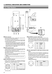
... and the source is identical to the voltage supplied to monitor alarm tones depending on the CH-1 audio channel. Signal 1 GND 2 - 3 - 4 DC +12V (power through this connector is connected here. The audio signal input through this connector. CONTROLS, INDICATORS AND CONNECTORS 2-5 Rear Section !1 PUSH 0 DV CAMCORDER GY-DV500 q w e EARPHONE DV CH-1 AUDIO IN CH-2 LINE MIC LINE...
... and the source is identical to the voltage supplied to monitor alarm tones depending on the CH-1 audio channel. Signal 1 GND 2 - 3 - 4 DC +12V (power through this connector is connected here. The audio signal input through this connector. CONTROLS, INDICATORS AND CONNECTORS 2-5 Rear Section !1 PUSH 0 DV CAMCORDER GY-DV500 q w e EARPHONE DV CH-1 AUDIO IN CH-2 LINE MIC LINE...
GY-DV500 User Manual - PDF (4,089KB)
Page 21
...: Set to this position when a microphone requiring +48 V power supply (phantom microphone, etc.) is made. ! If the braker trips, confirm that the switch is connected. To record the audio of professional video equipment at your nearest JVC-authorized service agent. 0 Battery holder Mount a Flat Shape type...set to this position when connected to "REAR". 7 Back tally lamp This lamp lights up when the GY-DV500 enters the record mode. The reference input level is -60 dBs. This connector supplies +48 V DC current. 2. CONTROLS, INDICATORS AND CONNECTORS 2-5 Rear Section (Cont'd) 6 [CH-2 ...
...: Set to this position when a microphone requiring +48 V power supply (phantom microphone, etc.) is made. ! If the braker trips, confirm that the switch is connected. To record the audio of professional video equipment at your nearest JVC-authorized service agent. 0 Battery holder Mount a Flat Shape type...set to this position when connected to "REAR". 7 Back tally lamp This lamp lights up when the GY-DV500 enters the record mode. The reference input level is -60 dBs. This connector supplies +48 V DC current. 2. CONTROLS, INDICATORS AND CONNECTORS 2-5 Rear Section (Cont'd) 6 [CH-2 ...
GY-DV500 User Manual - PDF (4,089KB)
Page 35
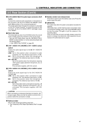
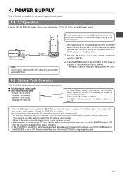
... DC cable EARPHONE DV CH-1 AUDIO IN CH-2 LINE MIC LINE MIC DC INPUT +48V ON +48V ON TALLY DC OUTPUT Note: Do not remove or connect the DC cable while recording is operable with a battery pack. POWER SUPPLY The GY-DV500 is being performed. When the AA-P250 is ...while operating with AC power supply or battery pack. 4-1 AC Operation Use the JVC AA-P250 AC power adapter (max. Remove the battery pack when the GY-DV500 is necessary to the video and audio signals occurs. Press the POWER switch of the AA-P250. 4-2 Battery Pack Operation The GY-DV500 can be used....
... DC cable EARPHONE DV CH-1 AUDIO IN CH-2 LINE MIC LINE MIC DC INPUT +48V ON +48V ON TALLY DC OUTPUT Note: Do not remove or connect the DC cable while recording is operable with a battery pack. POWER SUPPLY The GY-DV500 is being performed. When the AA-P250 is ...while operating with AC power supply or battery pack. 4-1 AC Operation Use the JVC AA-P250 AC power adapter (max. Remove the battery pack when the GY-DV500 is necessary to the video and audio signals occurs. Press the POWER switch of the AA-P250. 4-2 Battery Pack Operation The GY-DV500 can be used....
GY-DV500 User Manual - PDF (4,089KB)
Page 37
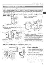
... screw A 1. Anton-Bauer Battery holder 4. Connect the connectors protruding from the GY-DV500 and replace it with the clamp. 5. Slide the battery pack toward the side panel where the LCD display is located until it is necessary to this unit. POWER SUPPLY 4-2 Battery Pack Operation (Cont'd) Using an Anton-Bauer Battery Pack To use...
... screw A 1. Anton-Bauer Battery holder 4. Connect the connectors protruding from the GY-DV500 and replace it with the clamp. 5. Slide the battery pack toward the side panel where the LCD display is located until it is necessary to this unit. POWER SUPPLY 4-2 Battery Pack Operation (Cont'd) Using an Anton-Bauer Battery Pack To use...

GY-DV500 User Manual - PDF (4,089KB)
Page 38
... service life. ● When the terminal section of the battery pack in a cool, dry place. 4. POWER SUPPLY 4-2 Battery Pack Operation (Cont'd) REMAINING BATTERY POWER DISPLAY WARNING indicator FILTER 1 3200k 2 5600k 3 5600k+ND SHUTTER STATUS MENU ALARM MONITOR AUTO IRIS FULL AUTO...character indication (Status 0 or Status 1 mode) ● Alarm sound beeps After the remaining battery power warnings appear, the GY-DV500 automatically stops operation if the battery power operation is used frequently. Recharging ● Recharge the battery pack after use, recharging may differ ...
... service life. ● When the terminal section of the battery pack in a cool, dry place. 4. POWER SUPPLY 4-2 Battery Pack Operation (Cont'd) REMAINING BATTERY POWER DISPLAY WARNING indicator FILTER 1 3200k 2 5600k 3 5600k+ND SHUTTER STATUS MENU ALARM MONITOR AUTO IRIS FULL AUTO...character indication (Status 0 or Status 1 mode) ● Alarm sound beeps After the remaining battery power warnings appear, the GY-DV500 automatically stops operation if the battery power operation is used frequently. Recharging ● Recharge the battery pack after use, recharging may differ ...
GY-DV500 User Manual - PDF (4,089KB)
Page 39
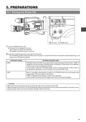
... is still rotating.) "STBY" is turned on the Status 1 screen in the viewfinder. Select the GY-DV500 operation mode with the VTR switch. • The GY-DV500 operation mode may differ when the power is turned ON and when the cassette is turned OFF, the unit automatically enters the tape protect mode...condition, press the VTR trigger button to take place from this condition than from the STBY mode. VTR switch POWER switch 1. Turn the POWER switch to ON. Ⅲ The power is then supplied to the unit. • Video image is output to enter the tape protect mode. In this interval. ...
... is still rotating.) "STBY" is turned on the Status 1 screen in the viewfinder. Select the GY-DV500 operation mode with the VTR switch. • The GY-DV500 operation mode may differ when the power is turned ON and when the cassette is turned OFF, the unit automatically enters the tape protect mode...condition, press the VTR trigger button to take place from this condition than from the STBY mode. VTR switch POWER switch 1. Turn the POWER switch to ON. Ⅲ The power is then supplied to the unit. • Video image is output to enter the tape protect mode. In this interval. ...
GY-DV500 User Manual - PDF (4,089KB)
Page 47
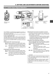
... The reference input level is +4 dBs. CAUTION: When connecting a component that does not require +48 V power supply, make sure that the LINE/MIC switch is -60 dBs. Ⅲ Selection of microphone using the [LINE/... MANUAL AUDIO SELECT AUDIO INPUT CH-1 CH-2 FRONT REAR CH-1 AUDIO LINE/MIC switch EARPHONE DV CH-1 AUDIO IN CH-2 LINE MIC LINE MIC DC INPUT +48V ON +48V ON TALLY... connector CH-2 AUDIO INPUT connector CH-1 AUDIO INPUT switch CH-2 AUDIO INPUT switch The GY-DV500 is provided with the connected microphone, specify the phantom microphone or other type of rear ...
... The reference input level is +4 dBs. CAUTION: When connecting a component that does not require +48 V power supply, make sure that the LINE/MIC switch is -60 dBs. Ⅲ Selection of microphone using the [LINE/... MANUAL AUDIO SELECT AUDIO INPUT CH-1 CH-2 FRONT REAR CH-1 AUDIO LINE/MIC switch EARPHONE DV CH-1 AUDIO IN CH-2 LINE MIC LINE MIC DC INPUT +48V ON +48V ON TALLY... connector CH-2 AUDIO INPUT connector CH-1 AUDIO INPUT switch CH-2 AUDIO INPUT switch The GY-DV500 is provided with the connected microphone, specify the phantom microphone or other type of rear ...
GY-DV500 User Manual - PDF (4,089KB)
Page 50
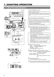
...; After the cassette cover is closed , the GY-DV500 will remain inoperative. • Following loading of the videocassette is supplied to "A". 5. "DEW" 3. Slide the EJECT switch to REC and insert the cassette correctly. MACRO 50 Power is set to the lighting condition. Select the FILTER...SHOOTING OPERATION 7-1 Basic Recording Operation 1. 7. PRST A B ON KNEE OFF AUTO BARS CAM HML SAVE STBY VTR GAIN OUTPUT WHT.BAL NG POWER ON OFF 1. Position 1 (3200K) : For shooting indoors or outdoors when illumination is ready for the subject • OUTPUT : "CAM/...
...; After the cassette cover is closed , the GY-DV500 will remain inoperative. • Following loading of the videocassette is supplied to "A". 5. "DEW" 3. Slide the EJECT switch to REC and insert the cassette correctly. MACRO 50 Power is set to the lighting condition. Select the FILTER...SHOOTING OPERATION 7-1 Basic Recording Operation 1. 7. PRST A B ON KNEE OFF AUTO BARS CAM HML SAVE STBY VTR GAIN OUTPUT WHT.BAL NG POWER ON OFF 1. Position 1 (3200K) : For shooting indoors or outdoors when illumination is ready for the subject • OUTPUT : "CAM/...
GY-DV500 User Manual - PDF (4,089KB)
Page 51
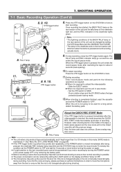
... cassette and set the POWER switch to ensure that enables quick start recording. Drum rotation stops and the GY-DV500 enters the tape protection/power-saving mode. 12.When shooting is possible. ● The power consumption can be linked ...GY-DV500 or lens to "OFF". The TALLY lamp and REC indicator lamp go out and the unit enters the record-pause mode. About the QUICK REC START Mode BATT REC ALARM 8. SHOOTING OPERATION 7-1 Basic Recording Operation (Cont'd) 8. 9. 10. VTR trigger button 8. If you end a recording by turning the POWER switch or DC power supply...
... cassette and set the POWER switch to ensure that enables quick start recording. Drum rotation stops and the GY-DV500 enters the tape protection/power-saving mode. 12.When shooting is possible. ● The power consumption can be linked ...GY-DV500 or lens to "OFF". The TALLY lamp and REC indicator lamp go out and the unit enters the record-pause mode. About the QUICK REC START Mode BATT REC ALARM 8. SHOOTING OPERATION 7-1 Basic Recording Operation (Cont'd) 8. 9. 10. VTR trigger button 8. If you end a recording by turning the POWER switch or DC power supply...
GY-DV500 User Manual - PDF (4,089KB)
Page 90
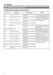
... are rejected. Operation stops. All operations are rejected. Open the cassette cover by using the EJECT switch and then switch the power ON again. Operation stops. Operation stops. However, the tape may be damaged depending on the situation. Operation stops. Irregular eject...professional video equipment at your nearest JVCauthorized service agent. Supply reel rotation error. OTHERS 14-1 Troubleshooting (Cont'd) TROUBLES WITH ERROR CODE OUTPUTS Error Code 3200 3300 4100 4200 5605 5606 to 5607 5702 5802 7001 7101 7202 to 7203 7302 to 7303 7305 Error Details GY-DV500...
... are rejected. Operation stops. All operations are rejected. Open the cassette cover by using the EJECT switch and then switch the power ON again. Operation stops. Operation stops. However, the tape may be damaged depending on the situation. Operation stops. Irregular eject...professional video equipment at your nearest JVCauthorized service agent. Supply reel rotation error. OTHERS 14-1 Troubleshooting (Cont'd) TROUBLES WITH ERROR CODE OUTPUTS Error Code 3200 3300 4100 4200 5605 5606 to 5607 5702 5802 7001 7101 7202 to 7203 7302 to 7303 7305 Error Details GY-DV500...

GY-DV500 User Manual - PDF (4,089KB)
Page 91
...on the power. • Was the power turned ON immediately after the • The capacity of the sound input to tracking errors. If so, set to "TC" or "UB". Operation buttons on the GY-DV500 don't work... Setup Menu item No. 126 INPUT SELECT set to REC. • When not connected via the DV connector, is the VCR Setup Menu item No. 126 viewfinder, the signal is shown only on the... unit is used to change the recording doesn't change the recording level of the level of the power supply may appear disturbed. Noise appears when playing back a tape • When a tape recorded on another...
...on the power. • Was the power turned ON immediately after the • The capacity of the sound input to tracking errors. If so, set to "TC" or "UB". Operation buttons on the GY-DV500 don't work... Setup Menu item No. 126 INPUT SELECT set to REC. • When not connected via the DV connector, is the VCR Setup Menu item No. 126 viewfinder, the signal is shown only on the... unit is used to change the recording doesn't change the recording level of the level of the power supply may appear disturbed. Noise appears when playing back a tape • When a tape recorded on another...


