
GY-DV500 User Manual - PDF (4,089KB)
Page 1
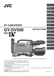
... S.S.F. (Super Scene Finder) ,,yy,,yy,,yy USINGEXTERNAL COMPONENTS SETUP MENU FEATURES OF THE CAMERA SECTION OTHERS * The illustration shows the GY-DV500 DV Camcorder with the optional lens viewfinder attached. Before operating this JVC product. SC96874-003 Retain this information for purchasing this unit, please read the instructions carefully to ensure the best possible...
... S.S.F. (Super Scene Finder) ,,yy,,yy,,yy USINGEXTERNAL COMPONENTS SETUP MENU FEATURES OF THE CAMERA SECTION OTHERS * The illustration shows the GY-DV500 DV Camcorder with the optional lens viewfinder attached. Before operating this JVC product. SC96874-003 Retain this information for purchasing this unit, please read the instructions carefully to ensure the best possible...
GY-DV500 User Manual - PDF (4,089KB)
Page 4
...for 0.75 lux (F1.4) illumination Employment of copyright holders. ● JVC cannot assume liabilities that both video and audio are recorded correctly. ●...GY-DV500U. Recording or playback in the LP mode is not possible. ● Due to manufacturing dispersion of tapes, we recommend not to record pictures within the first 2 to 3 minutes from the impossibility of normal recording or playback of the camcorder... as approximately 5 kg including lens, viewfinder, battery, and cassette. ● DV high-quality digital format The 4:1:1, 8-bit, 25 Mbps component digital processing of ...
...for 0.75 lux (F1.4) illumination Employment of copyright holders. ● JVC cannot assume liabilities that both video and audio are recorded correctly. ●...GY-DV500U. Recording or playback in the LP mode is not possible. ● Due to manufacturing dispersion of tapes, we recommend not to record pictures within the first 2 to 3 minutes from the impossibility of normal recording or playback of the camcorder... as approximately 5 kg including lens, viewfinder, battery, and cassette. ● DV high-quality digital format The 4:1:1, 8-bit, 25 Mbps component digital processing of ...
GY-DV500 User Manual - PDF (4,089KB)
Page 6
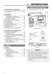
...from the tripod. Therefore, after mounting, make sure that these parts are engaged properly. ● When moving the GY-DV500 mounted on a Computer Monitor 81 13-4 Gain (Sensitivity) Adjustment 82 • Gain Switching 82 • Gain... ON OFF OPERATE/WARNING RESET MONITOR SELECT CH-1 AUDIO CH-2 LEVEL LIGHT ON OFF COUNTER CTL TC UB Camcorder (GY-DV500) Microphone CR230V32 Lithium battery Head cleaning tape OTHERS 14. Be sure to Use Skin Detail 84 1. ...; Alarm Indications 86 • Warnings in Viewfinder 88 • Troubles with DV Connector 64 11-2 Connecting a PC 65 12.
...from the tripod. Therefore, after mounting, make sure that these parts are engaged properly. ● When moving the GY-DV500 mounted on a Computer Monitor 81 13-4 Gain (Sensitivity) Adjustment 82 • Gain Switching 82 • Gain... ON OFF OPERATE/WARNING RESET MONITOR SELECT CH-1 AUDIO CH-2 LEVEL LIGHT ON OFF COUNTER CTL TC UB Camcorder (GY-DV500) Microphone CR230V32 Lithium battery Head cleaning tape OTHERS 14. Be sure to Use Skin Detail 84 1. ...; Alarm Indications 86 • Warnings in Viewfinder 88 • Troubles with DV Connector 64 11-2 Connecting a PC 65 12.
GY-DV500 User Manual - PDF (4,089KB)
Page 18
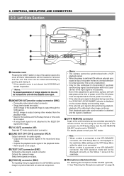
...continues. Outputs the camera image. This is output through the VCR section. CONTROLS, INDICATORS AND CONNECTORS 2-3 Left Side Section q w e r PUSH DV CAMCORDER GY-DV500 Y/C OUT MONITOR OUT LINE OUT CH-1 CH-2 VTR REMOTE SYNC IN TEST OUT MIC IN LENS i u y t 1 Cassette cover Pressing ...VTR REMOTE] connector A part of this cover so that a videocassette can be synchronized with an external component. For details, please consult your JVC dealer. Note: • When a cable is input, the screen moves in the viewfinder. 8 Microphone attachment holes For attaching the microphone holder...
...continues. Outputs the camera image. This is output through the VCR section. CONTROLS, INDICATORS AND CONNECTORS 2-3 Left Side Section q w e r PUSH DV CAMCORDER GY-DV500 Y/C OUT MONITOR OUT LINE OUT CH-1 CH-2 VTR REMOTE SYNC IN TEST OUT MIC IN LENS i u y t 1 Cassette cover Pressing ...VTR REMOTE] connector A part of this cover so that a videocassette can be synchronized with an external component. For details, please consult your JVC dealer. Note: • When a cable is input, the screen moves in the viewfinder. 8 Microphone attachment holes For attaching the microphone holder...
GY-DV500 User Manual - PDF (4,089KB)
Page 20
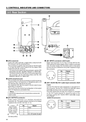
...according to the unit (DC 12V max. 0.1 A). 4 1 3 2 (Surface profile) No. CONTROLS, INDICATORS AND CONNECTORS 2-5 Rear Section !1 PUSH 0 DV CAMCORDER GY-DV500 q w e EARPHONE DV CH-1 AUDIO IN CH-2 LINE MIC LINE MIC DC INPUT +48V ON +48V ON TALLY DC OUTPUT i o u Y/C OUT MONITOR OUT LINE OUT CH...-1 CH-2 VTR REMOTE SYNC IN B TEST OUTPUT MIC LENS BREAKER rt y 1 [DV] connector Using a DV cable (optional), a digital video component with the AAP250 optional AC power adapter. The supply voltage is used to the power supplied through...
...according to the unit (DC 12V max. 0.1 A). 4 1 3 2 (Surface profile) No. CONTROLS, INDICATORS AND CONNECTORS 2-5 Rear Section !1 PUSH 0 DV CAMCORDER GY-DV500 q w e EARPHONE DV CH-1 AUDIO IN CH-2 LINE MIC LINE MIC DC INPUT +48V ON +48V ON TALLY DC OUTPUT i o u Y/C OUT MONITOR OUT LINE OUT CH...-1 CH-2 VTR REMOTE SYNC IN B TEST OUTPUT MIC LENS BREAKER rt y 1 [DV] connector Using a DV cable (optional), a digital video component with the AAP250 optional AC power adapter. The supply voltage is used to the power supplied through...
GY-DV500 User Manual - PDF (4,089KB)
Page 43
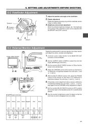
... that the screen turns entirely blue. 4. Brightness and contrast adjustment When the ambient brightness changes, etc., the brightness and contrast of the GY-DV500. 2. Y/C OUT MONITOR OUT LINE OUT CH-1 CH-2 VTR REMOTE SYNC IN TEST OUTPUT MIC IN LENS 2. If the phase ... G and B will all appear). 8. 6. Eyepiece 1. 2. Diopter adjustment Rotate the eyepiece focusing ring until the viewfinder screen image is visible. DV CAMCORDER GY-DV500 3.~8. Adjust the position and angle of the monitor so that there is no difference in step 4. 7. Set the monitor's BLUE CHECK function ...
... that the screen turns entirely blue. 4. Brightness and contrast adjustment When the ambient brightness changes, etc., the brightness and contrast of the GY-DV500. 2. Y/C OUT MONITOR OUT LINE OUT CH-1 CH-2 VTR REMOTE SYNC IN TEST OUTPUT MIC IN LENS 2. If the phase ... G and B will all appear). 8. 6. Eyepiece 1. 2. Diopter adjustment Rotate the eyepiece focusing ring until the viewfinder screen image is visible. DV CAMCORDER GY-DV500 3.~8. Adjust the position and angle of the monitor so that there is no difference in step 4. 7. Set the monitor's BLUE CHECK function ...
GY-DV500 User Manual - PDF (4,089KB)
Page 63
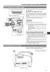
.... data are being written to the tape. • When writing to the beginning of recorded video and/or sound will be erased at the beginning. DV CAMCORDER GY-DV500 Y/C OUT MONITOR OUT LINE OUT CH-1 CH-2 VTR REMOTE SYNC IN TEST OUT MIC IN LENS VTR REMOTE connector 63 STOP button 2. data When... will be erased if new S.S.F. data is kept pressed in the writing position. In the case of important recordings, leave 5 seconds or more of the GY-DV500 is kept pressed. • The REW indicator blinks during the Scene End Cue Up mode. Press the STOP button to enter the stop mode...
.... data are being written to the tape. • When writing to the beginning of recorded video and/or sound will be erased at the beginning. DV CAMCORDER GY-DV500 Y/C OUT MONITOR OUT LINE OUT CH-1 CH-2 VTR REMOTE SYNC IN TEST OUT MIC IN LENS VTR REMOTE connector 63 STOP button 2. data When... will be erased if new S.S.F. data is kept pressed in the writing position. In the case of important recordings, leave 5 seconds or more of the GY-DV500 is kept pressed. • The REW indicator blinks during the Scene End Cue Up mode. Press the STOP button to enter the stop mode...
GY-DV500 User Manual - PDF (4,089KB)
Page 65
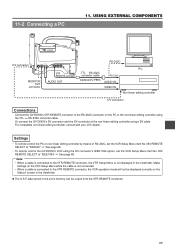
...DV CAMCORDER GY-DV500 DV connector Y/C OUT MONITOR OUT LINE OUT CH-1 CH-2 SYNC IN TEST OUT VTR REMOTE MIC IN LENS VTR REMOTE connector MONITOR OUT connector AUDIO OUT RS-232C TTL RS-232C converter cable (Optional VC-P893) RS-232C AUDIO IN VIDEO IN PC Non-linear editing controller DV... Connections Connect the GY-DV500's VTR REMOTE connector to the VTR REMOTE connector, the VTR Setup Menu is not displayed in the viewfinder. For compatible non-linear editing controller, consult with your JVC dealer. Make settings on the VTR Setup Menu while the cable is not connected. • ...
...DV CAMCORDER GY-DV500 DV connector Y/C OUT MONITOR OUT LINE OUT CH-1 CH-2 SYNC IN TEST OUT VTR REMOTE MIC IN LENS VTR REMOTE connector MONITOR OUT connector AUDIO OUT RS-232C TTL RS-232C converter cable (Optional VC-P893) RS-232C AUDIO IN VIDEO IN PC Non-linear editing controller DV... Connections Connect the GY-DV500's VTR REMOTE connector to the VTR REMOTE connector, the VTR Setup Menu is not displayed in the viewfinder. For compatible non-linear editing controller, consult with your JVC dealer. Make settings on the VTR Setup Menu while the cable is not connected. • ...
GY-DV500 User Manual - PDF (4,089KB)
Page 96
and many other countries. © 1999 VICTOR COMPANY OF JAPAN, LIMITED Printed in Japan, the U.S.A., the U.K. VICTOR COMPANY OF JAPAN, LIMITED ® is a registered trademark owned by VICTOR COMPANY OF JAPAN, LTD. ® is a registered trademark in Japan SC96874-003 GY-DV500 @DV CAMCORDER
and many other countries. © 1999 VICTOR COMPANY OF JAPAN, LIMITED Printed in Japan, the U.S.A., the U.K. VICTOR COMPANY OF JAPAN, LIMITED ® is a registered trademark owned by VICTOR COMPANY OF JAPAN, LTD. ® is a registered trademark in Japan SC96874-003 GY-DV500 @DV CAMCORDER


