

Instruction Manual
Page 2
...guarantee that interference will not occur in fire, electric shock, or other similar surface. INFORMATION FOR USA INFORMATION This equipment has been tested and found to radio communications. AVERTISSEMENT : POUR EVITER LES RISQUES D'INCENDIE OU D'ELECTROCUTION, NE PAS EXPOSER L'APPAREIL A L'HUMIDITE... device may fall, caus- NO USER SERVICEABLE PARTS INSIDE. CAUTION CHANGES OR MODIFICATIONS NOT APPROVED BY JVC COULD VOID USER'S AUTHORITY TO OPERATE THE EQUIPMENT. For Sweden VARNING Explosionsfara vid felaktigt batteribyte. For Norway ADVARSEL Lithiumbatteri-Eksplosjonsfare.
...guarantee that interference will not occur in fire, electric shock, or other similar surface. INFORMATION FOR USA INFORMATION This equipment has been tested and found to radio communications. AVERTISSEMENT : POUR EVITER LES RISQUES D'INCENDIE OU D'ELECTROCUTION, NE PAS EXPOSER L'APPAREIL A L'HUMIDITE... device may fall, caus- NO USER SERVICEABLE PARTS INSIDE. CAUTION CHANGES OR MODIFICATIONS NOT APPROVED BY JVC COULD VOID USER'S AUTHORITY TO OPERATE THE EQUIPMENT. For Sweden VARNING Explosionsfara vid felaktigt batteribyte. For Norway ADVARSEL Lithiumbatteri-Eksplosjonsfare.

Instruction Manual
Page 3
... to perform a test recording and confirm that both video and audio are recorded correctly. ● Recorded video and audio contents are not marked with the MiniDV symbol cannot be Used 9 1-6 Condensation 9 1-7 Characteristic CCD Phenomena 9 2. Eliminates flicker when shooting other screen pictures than PAL, such as you for purchasing the DV Camcorder GY-DV500. CONTENTS INTRODUCTION...
... to perform a test recording and confirm that both video and audio are recorded correctly. ● Recorded video and audio contents are not marked with the MiniDV symbol cannot be Used 9 1-6 Condensation 9 1-7 Characteristic CCD Phenomena 9 2. Eliminates flicker when shooting other screen pictures than PAL, such as you for purchasing the DV Camcorder GY-DV500. CONTENTS INTRODUCTION...

Instruction Manual
Page 8
... select the value of the digit to be adjusted with the LOG button 8 on page 20. MANUAL: The recording level can power the backup for test use the AUDIO LEVEL CH-1 recording level control on the tape. 8 [REC/FREE] run switch Selects the time code running mode while the time code...
... select the value of the digit to be adjusted with the LOG button 8 on page 20. MANUAL: The recording level can power the backup for test use the AUDIO LEVEL CH-1 recording level control on the tape. 8 [REC/FREE] run switch Selects the time code running mode while the time code...

Instruction Manual
Page 10
..., playback of the disturbed video image continues. This is not a malfunction. • Only for U-ver.). For details, please consult your JVC dealer. data stored in the unit's memory are rejected. 19 data is being written to the tape. • When the CONTINUE button ...in the search mode. See "Writing S.S.F. CONTROLS, INDICATORS AND CONNECTORS 2-3 Left Side Section q w e r PUSH DV CAMCORDER GY-DV500 Y/C OUT MONITOR OUT LINE OUT CH-1 CH-2 VTR REMOTE SYNC IN TEST OUT MIC IN LENS i u y t 1 Cassette cover Pressing the EJECT switch on the VTR Setup Menu while ...
..., playback of the disturbed video image continues. This is not a malfunction. • Only for U-ver.). For details, please consult your JVC dealer. data stored in the unit's memory are rejected. 19 data is being written to the tape. • When the CONTINUE button ...in the search mode. See "Writing S.S.F. CONTROLS, INDICATORS AND CONNECTORS 2-3 Left Side Section q w e r PUSH DV CAMCORDER GY-DV500 Y/C OUT MONITOR OUT LINE OUT CH-1 CH-2 VTR REMOTE SYNC IN TEST OUT MIC IN LENS i u y t 1 Cassette cover Pressing the EJECT switch on the VTR Setup Menu while ...

Instruction Manual
Page 11
...the CH-2 AUDIO IN connector 6. CONTROLS, INDICATORS AND CONNECTORS 2-5 Rear Section !1 PUSH 0 DV CAMCORDER GY-DV500 q w e EARPHONE DV CH-1 AUDIO IN CH-2 LINE MIC LINE MIC DC INPUT +48V ON +48V ON TALLY ... OUT MONITOR OUT LINE OUT CH-1 CH-2 VTR REMOTE SYNC IN B TEST OUTPUT MIC LEN BREAKER rt y 1 [DV] connector Using a DV cable (optional), a digital video component with the AAP250 optional AC power adapter... when the microphone is connected. To record the audio of professional video equipment at your nearest JVC-authorized service agent. 0 Battery holder Mount a Flat Shape ...
...the CH-2 AUDIO IN connector 6. CONTROLS, INDICATORS AND CONNECTORS 2-5 Rear Section !1 PUSH 0 DV CAMCORDER GY-DV500 q w e EARPHONE DV CH-1 AUDIO IN CH-2 LINE MIC LINE MIC DC INPUT +48V ON +48V ON TALLY ... OUT MONITOR OUT LINE OUT CH-1 CH-2 VTR REMOTE SYNC IN B TEST OUTPUT MIC LEN BREAKER rt y 1 [DV] connector Using a DV cable (optional), a digital video component with the AAP250 optional AC power adapter... when the microphone is connected. To record the audio of professional video equipment at your nearest JVC-authorized service agent. 0 Battery holder Mount a Flat Shape ...

Instruction Manual
Page 27
... if the iris is changed abruptly or the iris is released. (Save mode) To start recording from conventional models such as (GY-X1, GY-X2, and GY- If the VTR trigger button is pressed immediately after rewinding the tape for about 30 minutes, the unit enters the save mode,...Setup Menu item No. 396 SSF MODE is not changed by removing the battery pack. ● Before recording a scene that is particularly important, perform test shooting to ensure that the iris is set the POWER switch to start recording. SHOOTING OPERATION 7-1 Basic Recording Operation (Cont'd) 8. 9. 10. The ...
... if the iris is changed abruptly or the iris is released. (Save mode) To start recording from conventional models such as (GY-X1, GY-X2, and GY- If the VTR trigger button is pressed immediately after rewinding the tape for about 30 minutes, the unit enters the save mode,...Setup Menu item No. 396 SSF MODE is not changed by removing the battery pack. ● Before recording a scene that is particularly important, perform test shooting to ensure that the iris is set the POWER switch to start recording. SHOOTING OPERATION 7-1 Basic Recording Operation (Cont'd) 8. 9. 10. The ...

Instruction Manual
Page 33
..., the LOG indicator goes out. USING EXTERNAL COMPONENTS 11-1 Connecting a Video Component with DV Connector Rear section of the GY-DV500 from the video component with DV connector on the video component using the DV cable. Data to the S.S.F. data are recorded on the video component with...writing position. • The LOG indicator lights while S.S.F. See page 68. 64 Data PUSH The S.S.F. DV CAMCORDER GY-DV500 Y/C OUT MONITOR OUT LINE OUT CH-1 CH-2 VTR REMOTE SYNC IN TEST OUT MIC IN LENS VTR REMOTE connector 63 11. only Recording the playback image or audio of the...
..., the LOG indicator goes out. USING EXTERNAL COMPONENTS 11-1 Connecting a Video Component with DV Connector Rear section of the GY-DV500 from the video component with DV connector on the video component using the DV cable. Data to the S.S.F. data are recorded on the video component with...writing position. • The LOG indicator lights while S.S.F. See page 68. 64 Data PUSH The S.S.F. DV CAMCORDER GY-DV500 Y/C OUT MONITOR OUT LINE OUT CH-1 CH-2 VTR REMOTE SYNC IN TEST OUT MIC IN LENS VTR REMOTE connector 63 11. only Recording the playback image or audio of the...
Instruction Manual
Page 34
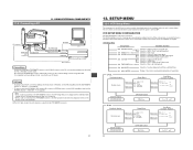
...DV CAMCORDER GY-DV500 DV connector Y/C OUT MONITOR OUT LINE OUT CH-1 CH-2 SYNC IN TEST OUT VTR REMOTE MIC IN LENS VTR REMOTE connector MONITOR OUT connector AUDIO OUT RS-232C TTL˱RS-232C converter cable (Optional VC-P893) RS-232C AUDIO IN VIDEO IN PC Non-linear editing controller DV... the viewfinder and on the Status1 screen in the viewfinder. Or connect the GY-DV500's DV connector and the DV connector of RS-232C, set while observing the menu in the memory and ...linear editing controller, consult with your JVC dealer. The S.S.F. 11-2 Connecting a PC PUSH 11.
...DV CAMCORDER GY-DV500 DV connector Y/C OUT MONITOR OUT LINE OUT CH-1 CH-2 SYNC IN TEST OUT VTR REMOTE MIC IN LENS VTR REMOTE connector MONITOR OUT connector AUDIO OUT RS-232C TTL˱RS-232C converter cable (Optional VC-P893) RS-232C AUDIO IN VIDEO IN PC Non-linear editing controller DV... the viewfinder and on the Status1 screen in the viewfinder. Or connect the GY-DV500's DV connector and the DV connector of RS-232C, set while observing the menu in the memory and ...linear editing controller, consult with your JVC dealer. The S.S.F. 11-2 Connecting a PC PUSH 11.

Instruction Manual
Page 46
...indication appears depending on the contents of the error code when some of professional video equipment at your nearest JVC-authorized service agent. All operations are rejected. All operations are rejected....WARNING (DEW)" indication appears when condensation is impossible to 7303 7305 Error Details GY-DV500 Operation Remedy Tape loading impossible. ALARM tone Dew condensation indicator AUTO OFF DEW... a self-test to ON again after the power is a microcomputer-controlled piece of an error code. Operation stops. The error code consists of professional video equipment at...
...indication appears depending on the contents of the error code when some of professional video equipment at your nearest JVC-authorized service agent. All operations are rejected. All operations are rejected....WARNING (DEW)" indication appears when condensation is impossible to 7303 7305 Error Details GY-DV500 Operation Remedy Tape loading impossible. ALARM tone Dew condensation indicator AUTO OFF DEW... a self-test to ON again after the power is a microcomputer-controlled piece of an error code. Operation stops. The error code consists of professional video equipment at...

Instruction Manual
Page 3
...the cabinet. No user serviceable parts inside. WARNING ON LITHIUM BATTERY The battery used in fire. CAUTION CHANGES OR MODIFICATIONS NOT APPROVED BY JVC COULD VOID USER'S AUTHORITY TO OPERATE THE EQUIPMENT. This unit should be determined by turning the equipment off and on a circuit different...that interference will not occur in a residential installation. NO USER SERVICEABLE PARTS INSIDE. INFORMATION FOR USA INFORMATION This equipment has been tested and found to qualified service personnel. Ce magnétoscope ne doit être utilisé que sur du courant direct en 12V...
...the cabinet. No user serviceable parts inside. WARNING ON LITHIUM BATTERY The battery used in fire. CAUTION CHANGES OR MODIFICATIONS NOT APPROVED BY JVC COULD VOID USER'S AUTHORITY TO OPERATE THE EQUIPMENT. This unit should be determined by turning the equipment off and on a circuit different...that interference will not occur in a residential installation. NO USER SERVICEABLE PARTS INSIDE. INFORMATION FOR USA INFORMATION This equipment has been tested and found to qualified service personnel. Ce magnétoscope ne doit être utilisé que sur du courant direct en 12V...
Instruction Manual
Page 4
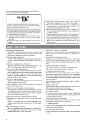
...played back on this camcorder. ● The transient section between scenes recorded on other units and those recorded on the rights of copyright holders. ● JVC cannot assume liabilities ...can be used to 2084.6 Hz. ● DV (i. Enables shooting at normal indoor illumination eliminating the need for purchasing the DV Camcorder GY-DV500. Copes with the range from the impossibility ...4 Enables transfer of the tape. ● Before recording important scenes, be sure to perform a test recording and confirm that may appear during playback due to F/11 while high S/ N is not ...
...played back on this camcorder. ● The transient section between scenes recorded on other units and those recorded on the rights of copyright holders. ● JVC cannot assume liabilities ...can be used to 2084.6 Hz. ● DV (i. Enables shooting at normal indoor illumination eliminating the need for purchasing the DV Camcorder GY-DV500. Copes with the range from the impossibility ...4 Enables transfer of the tape. ● Before recording important scenes, be sure to perform a test recording and confirm that may appear during playback due to F/11 while high S/ N is not ...

Instruction Manual
Page 15
... used when recording scenes one after another , the time codes become discontinuous at the change points between PRESET and REGEN. The battery is used for test use. It is used to select the menu item. 4 [ADVANCE/SELECT] button • During presetting of time code or user's bit, press to select the... and recalls the previous display contents. • In setup menu mode, this button is delivered without the battery installed. Set to save the set . The GY-DV500 is used to enter the VCR setup menu mode.
... used when recording scenes one after another , the time codes become discontinuous at the change points between PRESET and REGEN. The battery is used for test use. It is used to select the menu item. 4 [ADVANCE/SELECT] button • During presetting of time code or user's bit, press to select the... and recalls the previous display contents. • In setup menu mode, this button is delivered without the battery installed. Set to save the set . The GY-DV500 is used to enter the VCR setup menu mode.

Instruction Manual
Page 18
.... Even if SC adjustment is not output. 5 [TEST OUT] connector (BNC) Composite video signal output connector. CONTROLS, INDICATORS AND CONNECTORS 2-3 Left Side Section q w e r PUSH DV CAMCORDER GY-DV500 Y/C OUT MONITOR OUT LINE OUT CH-1 CH-2 VTR REMOTE SYNC IN TEST OUT MIC IN LENS i u y t 1 Cassette... cover Pressing the EJECT switch on /off. For details, please consult your JVC dealer. An EE image is output during recording...
.... Even if SC adjustment is not output. 5 [TEST OUT] connector (BNC) Composite video signal output connector. CONTROLS, INDICATORS AND CONNECTORS 2-3 Left Side Section q w e r PUSH DV CAMCORDER GY-DV500 Y/C OUT MONITOR OUT LINE OUT CH-1 CH-2 VTR REMOTE SYNC IN TEST OUT MIC IN LENS i u y t 1 Cassette... cover Pressing the EJECT switch on /off. For details, please consult your JVC dealer. An EE image is output during recording...

Instruction Manual
Page 20
..., etc. Signal 1 GND 2 - 3 - 4 DC +12V (power through this connector. CONTROLS, INDICATORS AND CONNECTORS 2-5 Rear Section !1 PUSH 0 DV CAMCORDER GY-DV500 q w e EARPHONE DV CH-1 AUDIO IN CH-2 LINE MIC LINE MIC DC INPUT +48V ON +48V ON TALLY DC OUTPUT i o u Y/C OUT MONITOR OUT LINE OUT ...CH-1 CH-2 VTR REMOTE SYNC IN B TEST OUTPUT MIC LENS BREAKER rt y 1 [DV] connector Using a DV cable (optional), a digital video component with the AAP250 optional AC power adapter. This connector is switched to the ...
..., etc. Signal 1 GND 2 - 3 - 4 DC +12V (power through this connector. CONTROLS, INDICATORS AND CONNECTORS 2-5 Rear Section !1 PUSH 0 DV CAMCORDER GY-DV500 q w e EARPHONE DV CH-1 AUDIO IN CH-2 LINE MIC LINE MIC DC INPUT +48V ON +48V ON TALLY DC OUTPUT i o u Y/C OUT MONITOR OUT LINE OUT ...CH-1 CH-2 VTR REMOTE SYNC IN B TEST OUTPUT MIC LENS BREAKER rt y 1 [DV] connector Using a DV cable (optional), a digital video component with the AAP250 optional AC power adapter. This connector is switched to the ...

Instruction Manual
Page 43
...1. Brightness and contrast adjustment When the ambient brightness changes, etc., the brightness and contrast of the GY-DV500. 2. Y/C OUT MONITOR OUT LINE OUT CH-1 CH-2 VTR REMOTE SYNC IN TEST OUTPUT MIC IN LENS 2. With the BLUE CHECK function ON, adjust the PHASE control of the monitor...the BRIGHT and CONT controls. 3. 3. Set the OUTPUT switch to BARS to the standard screen (R, G and B will all appear). 8. Eyepiece 1. 2. DV CAMCORDER GY-DV500 3.~8. SPOT L COMPRESS PRST A B AUTO OKFNFEE BARS CAM ON HML SAVE STBY VTR GAIN OUTPUT WHT.BAL NG POWER ON OFF Ⅲ SMTPE ...
...1. Brightness and contrast adjustment When the ambient brightness changes, etc., the brightness and contrast of the GY-DV500. 2. Y/C OUT MONITOR OUT LINE OUT CH-1 CH-2 VTR REMOTE SYNC IN TEST OUTPUT MIC IN LENS 2. With the BLUE CHECK function ON, adjust the PHASE control of the monitor...the BRIGHT and CONT controls. 3. 3. Set the OUTPUT switch to BARS to the standard screen (R, G and B will all appear). 8. Eyepiece 1. 2. DV CAMCORDER GY-DV500 3.~8. SPOT L COMPRESS PRST A B AUTO OKFNFEE BARS CAM ON HML SAVE STBY VTR GAIN OUTPUT WHT.BAL NG POWER ON OFF Ⅲ SMTPE ...

Instruction Manual
Page 51
Press the VTR trigger button on the GY-DV500 or lens to start of the lens' iris if the iris is changed abruptly or the iris is not changed by removing the battery pack. ● Before recording a scene that is particularly important, perform test shooting to OFF. ● The microphone may... is pushed very quickly and repeatedly, or the POWER switch is moved immediately after being pressed, the viewfinder REC indicator lamp may blink and the GY-DV500 may also occur.) 8. VTR trigger button 12. 9. About the QUICK REC START Mode BATT REC ALARM 8. However, when shooting starts in ...
Press the VTR trigger button on the GY-DV500 or lens to start of the lens' iris if the iris is changed abruptly or the iris is not changed by removing the battery pack. ● Before recording a scene that is particularly important, perform test shooting to OFF. ● The microphone may... is pushed very quickly and repeatedly, or the POWER switch is moved immediately after being pressed, the viewfinder REC indicator lamp may blink and the GY-DV500 may also occur.) 8. VTR trigger button 12. 9. About the QUICK REC START Mode BATT REC ALARM 8. However, when shooting starts in ...

Instruction Manual
Page 63
... tape, approximately 5 seconds of recorded video and/or sound will be erased if new S.S.F. REW button S.S.F. data stored in the memory of the GY-DV500 is kept pressed. • The REW indicator blinks during the Scene End Cue Up mode. data When S.S.F. data are recorded on page 65..., the previous data will be output by RS-232C control via the VTR REMOTE connector. Data PUSH The S.S.F. DV CAMCORDER GY-DV500 Y/C OUT MONITOR OUT LINE OUT CH-1 CH-2 VTR REMOTE SYNC IN TEST OUT MIC IN LENS VTR REMOTE connector 63 STOP button 2. For how to the S.S.F. LOG button 2. Press...
... tape, approximately 5 seconds of recorded video and/or sound will be erased if new S.S.F. REW button S.S.F. data stored in the memory of the GY-DV500 is kept pressed. • The REW indicator blinks during the Scene End Cue Up mode. data When S.S.F. data are recorded on page 65..., the previous data will be output by RS-232C control via the VTR REMOTE connector. Data PUSH The S.S.F. DV CAMCORDER GY-DV500 Y/C OUT MONITOR OUT LINE OUT CH-1 CH-2 VTR REMOTE SYNC IN TEST OUT MIC IN LENS VTR REMOTE connector 63 STOP button 2. For how to the S.S.F. LOG button 2. Press...

Instruction Manual
Page 65
... using the TTL ⇔ RS-232C converter cable. For compatible non-linear editing controller, consult with your JVC dealer. USING EXTERNAL COMPONENTS DV CAMCORDER GY-DV500 DV connector Y/C OUT MONITOR OUT LINE OUT CH-1 CH-2 SYNC IN TEST OUT VTR REMOTE MIC IN LENS VTR REMOTE connector MONITOR OUT connector AUDIO OUT RS-232C TTL RS...
... using the TTL ⇔ RS-232C converter cable. For compatible non-linear editing controller, consult with your JVC dealer. USING EXTERNAL COMPONENTS DV CAMCORDER GY-DV500 DV connector Y/C OUT MONITOR OUT LINE OUT CH-1 CH-2 SYNC IN TEST OUT VTR REMOTE MIC IN LENS VTR REMOTE connector MONITOR OUT connector AUDIO OUT RS-232C TTL RS...
Instruction Manual
Page 89
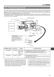
... 14. The error code consists of an error code. Depending on the status of professional video equipment at this time, indications may be inserted again. • Automatically stops operation or ejects the cassette...then set the POWER switch to identify the cause and displays the result in charge of the GY-DV500 at your nearest JVC-authorized service agent. WARNING indicator TALLY lamp VTR WARNING (HARD) VTR WARNING (DEW) FILTER 1...POWER switch OFF and then switching it performs a self-test to ON again after the power is a microcomputer-controlled piece of the other error codes are displayed...
... 14. The error code consists of an error code. Depending on the status of professional video equipment at this time, indications may be inserted again. • Automatically stops operation or ejects the cassette...then set the POWER switch to identify the cause and displays the result in charge of the GY-DV500 at your nearest JVC-authorized service agent. WARNING indicator TALLY lamp VTR WARNING (HARD) VTR WARNING (DEW) FILTER 1...POWER switch OFF and then switching it performs a self-test to ON again after the power is a microcomputer-controlled piece of the other error codes are displayed...