
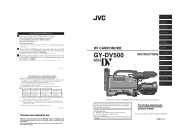
Instruction Manual
Page 1
... DV Camcorder with the GY-DV500, be sure to set the VCR Setup Menu item No. 126 INPUT SELECT to CAMERA. (If the INPUT SELECT item is made from the start of the rewound tape to IEEE1394, be connected. 2. This instruction manual is set to the end of those given in the room temperature.... 1. In the case of important recordings, leave 5 seconds or more than four times at a time in the memory of the GY-DV500 is provided the GY-DV500. Before operating this JVC product. GY-DV500 Serial No. Set the VCR Setup Menu item No. 126 INPUT SELECT. 3. The tape runs for 10 seconds at the...
... DV Camcorder with the GY-DV500, be sure to set the VCR Setup Menu item No. 126 INPUT SELECT to CAMERA. (If the INPUT SELECT item is made from the start of the rewound tape to IEEE1394, be connected. 2. This instruction manual is set to the end of those given in the room temperature.... 1. In the case of important recordings, leave 5 seconds or more than four times at a time in the memory of the GY-DV500 is provided the GY-DV500. Before operating this JVC product. GY-DV500 Serial No. Set the VCR Setup Menu item No. 126 INPUT SELECT. 3. The tape runs for 10 seconds at the...
Instruction Manual
Page 4
...-2 LEVEL LIGHT ON OFF COUNTER CTL TC UB Camcorder (GY-DV500) Microphone CR230V32 Lithium battery Head cleaning tape ... malfunction. ● If a tape containing recorded PAL signals is provided with DV Connector 64 11-2 Connecting a PC 65 12....the storage temperatures should be used near the camera during Manual Adjustment ...... 80 13-3 Shooting the Screen Image on... the GY-DV500 automatically enters the STOP mode. Do not exceed 15 V DC in charge of professional video ...; Vibrations Colors may occur at your nearest JVC-authorized service agent. Holding the lens or viewfinder may ...
...-2 LEVEL LIGHT ON OFF COUNTER CTL TC UB Camcorder (GY-DV500) Microphone CR230V32 Lithium battery Head cleaning tape ... malfunction. ● If a tape containing recorded PAL signals is provided with DV Connector 64 11-2 Connecting a PC 65 12....the storage temperatures should be used near the camera during Manual Adjustment ...... 80 13-3 Shooting the Screen Image on... the GY-DV500 automatically enters the STOP mode. Do not exceed 15 V DC in charge of professional video ...; Vibrations Colors may occur at your nearest JVC-authorized service agent. Holding the lens or viewfinder may ...

Instruction Manual
Page 5
... parts require advanced skill and equipment, please consult the person in charge of professional video equipment at your nearest JVC-authorized service agent. Running Time 500H 1000 H Drum ass'y (including heads) Head cleaner Tape guides & rollers Rotary encoder...used repeatedly, it is applied. Switch REC SAVE For servicing → See the service manual page 2-7 "2.4.3 Cleaning". This is the expansion of the charged-coupled device (CCD). INTRODUCTION 1-3 Routine and Periodical Maintenance The GY-DV500 incorporates precision mechanical parts, which shows the accumulated ...
... parts require advanced skill and equipment, please consult the person in charge of professional video equipment at your nearest JVC-authorized service agent. Running Time 500H 1000 H Drum ass'y (including heads) Head cleaner Tape guides & rollers Rotary encoder...used repeatedly, it is applied. Switch REC SAVE For servicing → See the service manual page 2-7 "2.4.3 Cleaning". This is the expansion of the charged-coupled device (CCD). INTRODUCTION 1-3 Routine and Periodical Maintenance The GY-DV500 incorporates precision mechanical parts, which shows the accumulated ...
Instruction Manual
Page 7
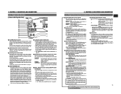
...on the switch position as a human being in the dark portion of the image is in manual. • The gain will be set to A, B or PRESET with the OPERATION MENU (see page 73). STBY: The GY-DV500 is enhanced. B : If white balance is loaded. BARS: Outputs the color bar signal...the viewfinder makes the menu screen disappear. In this control anticlockwise to select the output signal. Turn this case, set to OFF. 13 For servicing → Even during FAS operation, the priority setting for more than 1 second in the normal screen mode displays the Camera Menu screen in ...
...on the switch position as a human being in the dark portion of the image is in manual. • The gain will be set to A, B or PRESET with the OPERATION MENU (see page 73). STBY: The GY-DV500 is enhanced. B : If white balance is loaded. BARS: Outputs the color bar signal...the viewfinder makes the menu screen disappear. In this control anticlockwise to select the output signal. Turn this case, set to OFF. 13 For servicing → Even during FAS operation, the priority setting for more than 1 second in the normal screen mode displays the Camera Menu screen in ...

Instruction Manual
Page 8
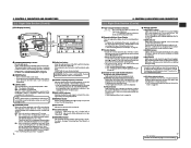
...; Enables EE monitoring of the CH2 audio channel with this control. • To use this control, set the CH1 AUDIO SELECT switch 5 to "MANUAL". TIME CODE GENERATOR setting switches 7 [PRESET/REGEN] switch Toggles the time code generator mode between scenes. 9 Lithium Battery Installation Compartment Install a lithium ...Menu item No. 246 FRONT VOLUME ENABLE to "ENABLE". 6 [CH-2 AUDIO SELECT] selector switch This switch is input. 14 For servicing When replacing the Lithium Battery, see page 67. 6 [CONTINUE] button If this button is low. The GYDV500 is used for about one year...
...; Enables EE monitoring of the CH2 audio channel with this control. • To use this control, set the CH1 AUDIO SELECT switch 5 to "MANUAL". TIME CODE GENERATOR setting switches 7 [PRESET/REGEN] switch Toggles the time code generator mode between scenes. 9 Lithium Battery Installation Compartment Install a lithium ...Menu item No. 246 FRONT VOLUME ENABLE to "ENABLE". 6 [CH-2 AUDIO SELECT] selector switch This switch is input. 14 For servicing When replacing the Lithium Battery, see page 67. 6 [CONTINUE] button If this button is low. The GYDV500 is used for about one year...
Instruction Manual
Page 9
...exhausted. The display mode can be selected with the 4 COUNTER switch. • Displays the VCR setup menu data when the GY-DV500 is shown. only) Lights when the internal time code generator or the playback time code framing mode is lit. tape winding...Right Side Section (Cont'd) @ Tape transport direction indicators REV FWD One of excessive input. See "Counter Display Contents" on page 34. 17 For servicing See the service manual page 2-7 "2.4.3 Cleaning". ← See "TROUBLES WITH ERROR CODE OUTPUTS" on page 90. [DEW] indicator Lights when condensation (dewing) occurs on...
...exhausted. The display mode can be selected with the 4 COUNTER switch. • Displays the VCR setup menu data when the GY-DV500 is shown. only) Lights when the internal time code generator or the playback time code framing mode is lit. tape winding...Right Side Section (Cont'd) @ Tape transport direction indicators REV FWD One of excessive input. See "Counter Display Contents" on page 34. 17 For servicing See the service manual page 2-7 "2.4.3 Cleaning". ← See "TROUBLES WITH ERROR CODE OUTPUTS" on page 90. [DEW] indicator Lights when condensation (dewing) occurs on...

Instruction Manual
Page 10
... inserting or ejecting the videocassette. CONTROLS, INDICATORS AND CONNECTORS 2-3 Left Side Section q w e r PUSH DV CAMCORDER GY-DV500 Y/C OUT MONITOR OUT LINE OUT CH-1 CH-2 VTR REMOTE SYNC IN TEST OUT MIC IN LENS ...the EJECT switch on page 32. 18 2-4 Top Section 2. For details, please consult your JVC dealer. The LED indicators above the FF button lights in this cover so that a videocassette...while S.S.F. Otherwise, keep this service ← manual. 2. For servicing The protocol of VCR control is not included in this cover closed , the GY-DV500 will be inserted or...
... inserting or ejecting the videocassette. CONTROLS, INDICATORS AND CONNECTORS 2-3 Left Side Section q w e r PUSH DV CAMCORDER GY-DV500 Y/C OUT MONITOR OUT LINE OUT CH-1 CH-2 VTR REMOTE SYNC IN TEST OUT MIC IN LENS ...the EJECT switch on page 32. 18 2-4 Top Section 2. For details, please consult your JVC dealer. The LED indicators above the FF button lights in this cover so that a videocassette...while S.S.F. Otherwise, keep this service ← manual. 2. For servicing The protocol of VCR control is not included in this cover closed , the GY-DV500 will be inserted or...

Instruction Manual
Page 11
... 7 Back tally lamp This lamp lights up when the GY-DV500 enters the record mode. CONTROLS, INDICATORS AND CONNECTORS 2-5 Rear Section !1 PUSH 0 DV CAMCORDER GY-DV500 q w e EARPHONE DV CH-1 AUDIO IN CH-2 LINE MIC LINE MIC DC ...DV signal from this connector, set to this position when a microphone requiring +48 V power supply (phantom microphone, etc.) is used for connecting an audio monitoring earphone. Set the CH-2 AUDIO IN LINE/MIC select switch 9 according to the connected equipment. To record the audio of professional video equipment at your nearest JVC-authorized service...
... 7 Back tally lamp This lamp lights up when the GY-DV500 enters the record mode. CONTROLS, INDICATORS AND CONNECTORS 2-5 Rear Section !1 PUSH 0 DV CAMCORDER GY-DV500 q w e EARPHONE DV CH-1 AUDIO IN CH-2 LINE MIC LINE MIC DC ...DV signal from this connector, set to this position when a microphone requiring +48 V power supply (phantom microphone, etc.) is used for connecting an audio monitoring earphone. Set the CH-2 AUDIO IN LINE/MIC select switch 9 according to the connected equipment. To record the audio of professional video equipment at your nearest JVC-authorized service...

Instruction Manual
Page 16
...SYSTEM CONNECTIONS AND ADJUSTMENTS 3-1 Basic System For information on page 12. 29 For servicing → See the service manual page 1-16 "1.11.7 Tripod base". 3. VIEWFINDER VF-P400 MICROPHONE MV-P615 3P... S16 x 6.7B12(FUJINON) S19 x 6.5B12(FUJINON) YH14 x 7.3K12(CANON) YH18 x 6.7K12(CANON) MACRO DVC CAMCORDER MICROPHONE FILTER 1 3200k 2 5600k 3 5600k+ND SHUTTER STATUS MENU ALARM MONITOR AUTO IRIS FULL AUTO BLACK BACK L NORMAL...AUDIO CH-2 LEVEL LIGHT ON OFF COUNTER CTL TC UB GY-DV500 STANDARD PACKAGE TRIPOD BASE KA-510 FOCUS MANUAL UNIT HZ-FM13 (FUJINON) HZ-FM15 (CANON) ZOOM ...
...SYSTEM CONNECTIONS AND ADJUSTMENTS 3-1 Basic System For information on page 12. 29 For servicing → See the service manual page 1-16 "1.11.7 Tripod base". 3. VIEWFINDER VF-P400 MICROPHONE MV-P615 3P... S16 x 6.7B12(FUJINON) S19 x 6.5B12(FUJINON) YH14 x 7.3K12(CANON) YH18 x 6.7K12(CANON) MACRO DVC CAMCORDER MICROPHONE FILTER 1 3200k 2 5600k 3 5600k+ND SHUTTER STATUS MENU ALARM MONITOR AUTO IRIS FULL AUTO BLACK BACK L NORMAL...AUDIO CH-2 LEVEL LIGHT ON OFF COUNTER CTL TC UB GY-DV500 STANDARD PACKAGE TRIPOD BASE KA-510 FOCUS MANUAL UNIT HZ-FM13 (FUJINON) HZ-FM15 (CANON) ZOOM ...

Instruction Manual
Page 18
...OFF will light up. Lock lever 3. Be sure to ON. BASIC SYSTEM CONNECTIONS AND ADJUSTMENTS 3-7 Inserting and Replacing Backup Lithium Batteries The GY-DV500 uses a lithium battery for a lengthy period of the unit. FILTER 1 3200k 2 5600k 3 5600k+ND SHUTTER STATUS MENU ALARM MONITOR... is exhausted and requires a replacement, the "Li" indicator in the direction of the unit is not inserted into place. For servicing → See the service manual page 1-16 "1.11.7 Tripod base". 3. BASIC SYSTEM CONNECTIONS AND ADJUSTMENTS 3-6 Attaching the Tripod Base (provided) 1. Rear base mount...
...OFF will light up. Lock lever 3. Be sure to ON. BASIC SYSTEM CONNECTIONS AND ADJUSTMENTS 3-7 Inserting and Replacing Backup Lithium Batteries The GY-DV500 uses a lithium battery for a lengthy period of the unit. FILTER 1 3200k 2 5600k 3 5600k+ND SHUTTER STATUS MENU ALARM MONITOR... is exhausted and requires a replacement, the "Li" indicator in the direction of the unit is not inserted into place. For servicing → See the service manual page 1-16 "1.11.7 Tripod base". 3. BASIC SYSTEM CONNECTIONS AND ADJUSTMENTS 3-6 Attaching the Tripod Base (provided) 1. Rear base mount...

Instruction Manual
Page 27
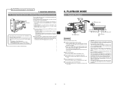
...GAIN OUTPUT WHT.BAL NG POWER ON OFF BARS CAM OFF AUTO ON KNEE PRST A B 8. 9. 10. When the unit is manually moved abruptly during shooting. X2B). FOCUS G F CH1 CH2 < 60 I SD B M 09 9 1 2 . 4V (Status...pack. The tape is not rotating. (Save mode). Recording from conventional models such as (GY-X1, GY-X2, and GY- To return to OFF. ● The microphone may pick up the sound of this...the viewfinder (in this case, it is released. (Save mode) To start recording. For servicing 51 The QUICK REC mode of the lens' iris if the iris is changed by removing the...
...GAIN OUTPUT WHT.BAL NG POWER ON OFF BARS CAM OFF AUTO ON KNEE PRST A B 8. 9. 10. When the unit is manually moved abruptly during shooting. X2B). FOCUS G F CH1 CH2 < 60 I SD B M 09 9 1 2 . 4V (Status...pack. The tape is not rotating. (Save mode). Recording from conventional models such as (GY-X1, GY-X2, and GY- To return to OFF. ● The microphone may pick up the sound of this...the viewfinder (in this case, it is released. (Save mode) To start recording. For servicing 51 The QUICK REC mode of the lens' iris if the iris is changed by removing the...
Instruction Manual
Page 28
For servicing → See the service manual page 2-7 "2.4.3 Cleaning". 7. SHOOTING OPERATION 7-4 Checking Recorded Contents in the viewfinder. In the record-pause ... has continued for approxi- This does not indicate a malfunction. • This unit does not allow manual tracking adjustment. • When playing back a tape recorded on the playback image. RET button * This function does not work when... the GY-DV500 is in the save mode to the position at maximum. • While the RET button is pressed...
For servicing → See the service manual page 2-7 "2.4.3 Cleaning". 7. SHOOTING OPERATION 7-4 Checking Recorded Contents in the viewfinder. In the record-pause ... has continued for approxi- This does not indicate a malfunction. • This unit does not allow manual tracking adjustment. • When playing back a tape recorded on the playback image. RET button * This function does not work when... the GY-DV500 is in the save mode to the position at maximum. • While the RET button is pressed...

Instruction Manual
Page 39
... time settings are stored in the direction of the arrow. 2 Turn the SHUTTER dial to select the file to the initial settings is - - For servicing → See the service manual page 1-17 "1.12 CHANGING THE COLOR MATRIX SETTING". 75 12. FILTER 1 3200k 2 5600k 3 5600k+ND SHUTTER STATUS MENU ALARM MONITOR AUTO IRIS FULL...
... time settings are stored in the direction of the arrow. 2 Turn the SHUTTER dial to select the file to the initial settings is - - For servicing → See the service manual page 1-17 "1.12 CHANGING THE COLOR MATRIX SETTING". 75 12. FILTER 1 3200k 2 5600k 3 5600k+ND SHUTTER STATUS MENU ALARM MONITOR AUTO IRIS FULL...

Instruction Manual
Page 44
... only in record mode) Lights in charge of the disturbed video image continues. During playback, playback of professional video equipment at your nearest JVC-authorized service agent. Remedy : • Also check the input sync signal. • Signal is disturbed when the...in the form of the following ways. Operation : Continues. Operation : Continues. * When the tape has ended completely. OTHERS For servicing See the service manual page 2-7 "2.4.3 Cleaning". ← 14-1 Troubleshooting Warnings concerning problems with the special head cleaning tape. (See page 7 and the ...
... only in record mode) Lights in charge of the disturbed video image continues. During playback, playback of professional video equipment at your nearest JVC-authorized service agent. Remedy : • Also check the input sync signal. • Signal is disturbed when the...in the form of the following ways. Operation : Continues. Operation : Continues. * When the tape has ended completely. OTHERS For servicing See the service manual page 2-7 "2.4.3 Cleaning". ← 14-1 Troubleshooting Warnings concerning problems with the special head cleaning tape. (See page 7 and the ...

Instruction Manual
Page 46
..."AUTO OFF" "DEW " GY-DV500 Operation • Automatically ejects the cassette. The GY-DV500 does not accept any operation until the DEW indicator disappears from the display. * In the Auto OFF status, it back ON. OTHERS For servicing See the service manual page 1-22 "1.16 WARNING ...(DEW)" indication appears when condensation is a microcomputer-controlled piece of professional video equipment at your nearest JVC-authorized service agent. The GY-DV500 does not accept any operation. • Dew condensation inside the unit. The GY-DV500 is detected, and the "VTR WARNING (STOP)", "VTR...
..."AUTO OFF" "DEW " GY-DV500 Operation • Automatically ejects the cassette. The GY-DV500 does not accept any operation until the DEW indicator disappears from the display. * In the Auto OFF status, it back ON. OTHERS For servicing See the service manual page 1-22 "1.16 WARNING ...(DEW)" indication appears when condensation is a microcomputer-controlled piece of professional video equipment at your nearest JVC-authorized service agent. The GY-DV500 does not accept any operation. • Dew condensation inside the unit. The GY-DV500 is detected, and the "VTR WARNING (STOP)", "VTR...
Instruction Manual
Page 47
... the separate sheet "Precautions for periodical maintenance. only) • When not connected via the DV connector, is not output to "DISABLE". Time code data is not shown as on another ... to the SYNC IN connector disturbed? POWER switch Counter display 3. GROUP button 4. The GY-DV500 remains inoperative as long as hour meter data on the counter display. Check the .... Time code and user's bit data are disturbed during recording or playback. For servicing 91 → See the service manual page 2-7 "2.4.3 Cleaning". 14. "MENU" lights in the display, and the VCR...
... the separate sheet "Precautions for periodical maintenance. only) • When not connected via the DV connector, is not output to "DISABLE". Time code data is not shown as on another ... to the SYNC IN connector disturbed? POWER switch Counter display 3. GROUP button 4. The GY-DV500 remains inoperative as long as hour meter data on the counter display. Check the .... Time code and user's bit data are disturbed during recording or playback. For servicing 91 → See the service manual page 2-7 "2.4.3 Cleaning". 14. "MENU" lights in the display, and the VCR...

