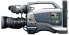
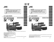
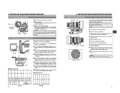
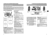
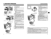
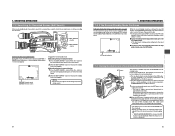
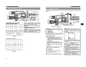
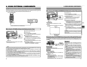
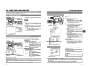
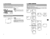
Wired Peer-to-Peer Connections from Streamcorder to Computer
Page 2
In the example above , both devices MUST have different menu structures; What You Need • GY-DV300 camera with a KA-DV300 or KA-DV350 Network Pack, a GY-DV5000 camera with a KADV5000 Network Pack, or a BR-DV6000 VTR with a wired LAN interface, you ...just press the menu button; Please refer to your User's Guide for the Network Pack initialization sequence to finish. Although IP addresses of all connected devices, IP addresses and Netmask settings must be configured manually...
Wireless Peer-to-Peer Connections from Streamcorder to Computer
Page 3
... a wireless LAN interface, you can use Streamcorder with the other settings. What You Need • GY-DV300 camera with a KA-DV300/350 Network Pack, GY-DV5000 camera with a KA-DV5000 Network Pack, or a BR-DV6000 VTR with an SA-DV6000 Network Pack. • A wireless ...DV5000, you just have slightly different menu structures. Turn the camera or VTR power ON and wait for the Streamcorder. You will be set : • HOST NAME - Please refer to a different computer. When set to 'ON', this must configure it for the first time or when connecting to your owners' manual...
GY-DV5000U 3-CCD Professional DV Camcorder 92 page instruction manual
Page 1
...performance. Thank you for service purpose with modified contents. This instruction manual is specially edited for purchasing this JVC product. UE CAUTION This section of instruction manual is not recommended to use this unit, please read the instructions ...CAMERA SECTION OTHERS * The illustration shows the GY-DV5000 DV Camcorder with the optional lens and viewfinder Microphone holder, Microphone attached. GY-DV5000 Serial No. Before operating this section for the substitution of the original book included in the merchandise. Model No. This instruction manual...
GY-DV5000U 3-CCD Professional DV Camcorder 92 page instruction manual
Page 5
...the unit at your nearest JVC-authorized service agent. When storing the GY-DV5000 for a long time, the...176;C to 40°C and a relative humidity of professional video equipment at a temperature or humidity outside the allowable ...METER DISPLAY" on , but the impact on the CCD elements could be serious as this may be sure to... the unit in places; • subject to the service manual page. 2-6 "2.4.3 Cleaning" 7 Do not exceed 15 V...voltage is also recommended to apply periodical maintenance (inspection) to the camera body. To prevent deformation of failure. Running Time 500H 1000 H...
GY-DV5000U 3-CCD Professional DV Camcorder 92 page instruction manual
Page 6
...covered with droplets allowing the tape to be Used ● Use JVC's videocassette tapes marked with its tape not being overwritten. ●...condensation (dewing). Do not continue to be Used The GY-DV5000 can be used upside down in a cold place and ...camera under conditions where the temperature of the head cleaning tape. In such a case, it is then carried to the service manual page. 1-9 "White blemish derection" ← 1. The CCD..."HEAD CLEANING REQUIRED!" Standard DV videocassette: LA-DV276, LA-DV186, LADV124 Mini DV videocassette: M-DV63PRO, M-DV60, M-DV30 * Do not...
GY-DV5000U 3-CCD Professional DV Camcorder 92 page instruction manual
Page 16
... with the FRONT TALLY item on page 30. 8 9 3. PROTEC) 1.5" VIEW FINDER VF-P115B VF-P116 DV CAMCORDER ZOOM LENS S14 × 7.3B12U(FUJINON) S17 × 6.6BRM(FUJINON) S20 × 6.4B12U(FUJINON) ...CH-1 CH-2 AUDIO INPUT AUDIO SELECT CH-1 CH-2 AUTO MANUAL DISPLAY PULL OPEN GY-DV5000 STANDARD PACKAGE TRIPOD BASE KA-550U FOCUS MANUAL UNIT HZ-FM13 (FUJINON) HZ-FM15 (CANON) ZOOM ...brightness adjustment To adjust the brightness of the cameraman. To prevent this light from turning on the camera. 3 Connector Connect to prevent the tally light 7 from coming off . 7 Tally light Lights ...
GY-DV5000U 3-CCD Professional DV Camcorder 92 page instruction manual
Page 18
...PHONES DV REAR AUDIO IN DC OUT DC IN TALLY Do not use any impact or vibration should be used up, set to be avoided as this may occur if the DC cable is connected or disconnected while operating with AC power supply or battery pack. 4-1 AC Operation Use the JVC ... the front so that these parts are set the POWER switch to be connected directly to CAMERA. 3. POWER SUPPLY The GY-DV5000 is supplied to the VTR section and the camera. * For details, read the instruction manual of the GY-DV5000 to the DC IN connector, the power supply from the upward direction and slide it . 4....
GY-DV5000U 3-CCD Professional DV Camcorder 92 page instruction manual
Page 20
... the record-standby or STOP mode. 2. When a videocassette is changed. Place the GY-DV5000 in the viewfinder or on the camera is still set the POWER switch to OFF before the power is loaded, the GY-DV5000 enters the record-standby mode automatically. POWER SUPPLY 4-2 Battery Pack Operation (Optional) (Cont...POWER VTR ON OFF OPEN CH-1 AUDIO LEVEL CH-2 LCD BRIGHT FRONT REAR CH-1 CH-2 AUDIO INPUT AUDIO SELECT CH-1 CH-2 AUTO MANUAL DISPLAY PULL OPEN MENU AUTO IRIS FULL AUTO BACK L NORMAL SPOT L BLACK LOLUX STRETCH NORMAL COMPRESS MODE VTR CAM POWER VTR ON OFF...
GY-DV5000U 3-CCD Professional DV Camcorder 92 page instruction manual
Page 24
...AUDIO LEVEL CH-2 LCD BRIGHT FRONT REAR CH-1 CH-2 AUDIO INPUT AUDIO SELECT CH-1 CH-2 AUTO MANUAL DISPLAY PULL OPEN 1. C. [OUTPUT] switch: Set to the GY-DV5000 and an AC outlet or mount a charged battery on the CAMERA OPERATION menu screen. ☞ See page 69. ● To record using the AC power adapter...from a power supply. PREPARATIONS 5-5 Charging the Built-in Battery The built-in the battery case on the GY-DV5000 to charge AC outlet AA-P250 AC power adapter DC cable PHONES DV REAR AUDIO IN DC OUT DC IN TALLY 1. Set the POWER switch on the rear section of the ...
GY-DV5000U 3-CCD Professional DV Camcorder 92 page instruction manual
Page 25
...is more than 3 meters from the CHROMA control adjustment in brightness between the color bars 1 and 8, 7 and D, start again from the camera. Adjust the CHROMA control of the viewfinder screen can be used in brightness between the color bars 1 and 8, 7 and D. 5. Set the...monitor's BLUE CHECK function to OFF to switch the monitor back to M (Manual). 3. RET M A W T 1. 2. 7. 8. 10. MEMO: ACCU FOCUS can be changed by turning the iris ring. Eyepiece 1. MEMO: The screen size of the GY-DV5000. 2. Use the monitor's brightness control to adjust back focus when the ...
GY-DV5000U 3-CCD Professional DV Camcorder 92 page instruction manual
Page 26
... re-adjust the white balance. REGEN FREE REC PRST PHONES DV REAR AUDIO IN DC OUT DC IN TALLY REAR AUDIO IN connector The GY-DV5000 is not suitable. FRONT : The sound from the FRONT... CH-2 LCD BRIGHT FRONT REAR CH-1 CH-2 AUDIO INPUT AUDIO SELECT CH-1 CH-2 AUTO MANUAL DISPLAY PULL OPEN CH-1 AUDIO INPUT switch CH-2 AUDIO INPUT LCD BRIGHT DISPLAY switch AUDIO INPUT... using the CH-2 AUDIO INPUT switch. Two channels of light (color temperature) varies depending on the CAMERA OPERATION menu screen. LINE : Set to the connected component. 49 6. "AUTO WHITE A, B OPERATION...
GY-DV5000U 3-CCD Professional DV Camcorder 92 page instruction manual
Page 28
... supplied to open the cassette cover. 2 Press the EJECT button to take out the videocassette. ■ When the power should be changed abruptly during DV signal input. 7.8. Also, the time code does not continue. (Some overlap may pick up . If this condition set to the next recorded scene ... AUDIO LEVEL CH-2 CH A CH 6. Set the POWER switch to ON. ● Power is manually moved abruptly during recording. The CAM indicator lights up the sound of recording. The GY-DV5000 is in the Camera mode when the CAM indicator is on page 77. ● If the VTR trigger button is pressed...
GY-DV5000U 3-CCD Professional DV Camcorder 92 page instruction manual
Page 29
...CH-2 LCD BRIGHT FRONT REAR CH-1 CH-2 AUDIO INPUT AUDIO SELECT CH-1 CH-2 AUTO MANUAL DISPLAY PULL OPEN EDITSEARCH ATUS EDIT SEARCH + button EDIT SEARCH - button is reengaged. button ...Record-Standby Mode (Recording Check Function) RET button This function is available only when the GY-DV5000 is possible to search for approximately 15 seconds at the normal speed. 2. MEMO: ●...Press the EDIT SEARCH + button. In the record-standby mode, press the RET button on the camera lens section. • The tape is slightly rewound and played back for about 3 seconds. ■...
GY-DV5000U 3-CCD Professional DV Camcorder 92 page instruction manual
Page 30
... CH-1 CH-2 AUDIO INPUT AUDIO SELECT CH-1 CH-2 AUTO MANUAL DISPLAY PULL OPEN BLANK SEARCH REW STOP FF PLAY STILL MODE VTR CAM Still button PLAY button STOP button POWER switch MODE switch MEMO: ● The GY-DV5000 can be played back. 1. Tape protect mode: Drum rotation... Cyan Green Magenta Red Blue Blue Black Magenta Black Cyan Black White Black White Black Whether the camera image should be output or whether the color bar of videocassettes: • DV videocassette • MiniDV videocassette • DVCAM videocassette ● Tapes recorded in the LP mode cannot...
GY-DV5000U 3-CCD Professional DV Camcorder 92 page instruction manual
Page 32
... on the master unit. Recording operation is performed on the backup equipment simultaneously with start and stop of the GY-DV5000's Camera Image and Sound Through the DV Connector The GY-DV5000's camera image and sound can be performed, reduce the sound volume of the audio component, speaker, etc., connected to...AUDIO LEVEL CH-2 LCD BRIGHT FRONT REAR CH-1 CH-2 AUDIO INPUT AUDIO SELECT CH-1 CH-2 AUTO MANUAL DISPLAY PULL OPEN DV cable Signal flow Backup unit Connections Use the GY-DV5000 as on the master side can be recorded for backup on the player, sound may not be played...
GY-DV5000U 3-CCD Professional DV Camcorder 92 page instruction manual
Page 33
...LEVEL CH-2 LCD BRIGHT FRONT REAR CH-1 CH-2 AUDIO INPUT AUDIO SELECT CH-1 CH-2 AUTO MANUAL DISPLAY PULL OPEN COUNTER switch LCD BRIGHT DISPLAY CH-1 AUDIO LEVEL CH-2 MONITOR SELECT CH-1 MIX... EXECUTE blink. MENU --- FILE MANAGE.. The method for setting is preset in scene accuracy. CAMERA OPERATION.. OTHERS.. STBY 01/02/03 01:23:45 Status 1 screen 10-2 Presetting and ...'s bit data to make the following settings. ■ TC GENE. TIME CODE OPERATION The GY-DV5000 records SMPTE-standard time codes and user's bits. Use this difference, the mode called "drop...
GY-DV5000U 3-CCD Professional DV Camcorder 92 page instruction manual
Page 34
...ADJUST screen FILE MANAGE screen 65 The menu screen to be displayed correctly by DV components for general consumer use, as some of these are stored in the GYDV5000's...AUDIO LEVEL CH-2 LCD BRIGHT FRONT REAR CH-1 CH-2 AUDIO INPUT AUDIO SELECT CH-1 CH-2 AUTO MANUAL DISPLAY PULL OPEN LCD BRIGHT DISPLAY CH-1 AUDIO LEVEL CH-2 MONITOR SELECT CH-1 MIX CH-2 AUDIO... 4:3 PAGE BACK CAM CAMERA OPERATION screen --- When saving menu setting contents that remain more than 2 hours may occur in continuation of files (FILE CAM1, FILE CAM2) on the GY-DV5000. TC/UB/CLOCK.. ...
GY-DV5000U 3-CCD Professional DV Camcorder 92 page instruction manual
Page 35
... LCD BRIGHT FRONT REAR CH-1 CH-2 AUDIO INPUT AUDIO SELECT CH-1 CH-2 AUTO MANUAL DISPLAY PULL OPEN SHUTTER dial STATUS button SHUTTER STA MENU Cursor MENU screen --- AUDIO/...● The CANCEL indicator in the specified storage location are read out. The power is reset. CAMERA OPERATION.. TOP MENU screen --- FILE MANAGE --- OTHERS.. If the OUTPUT CHAR. Change the setting.... dial. ■ To change multiple items, repeat the procedures in two types of the GY-DV5000 with the item to the factory settings. ■ Display the FILE MANAGE menu screen. ...
GY-DV5000U 3-CCD Professional DV Camcorder 92 page instruction manual
Page 45
... input. DV signal is 3 minutes or less. (Only To continue the recording, prepare a new tape or replace displayed in the recording mode and during playback.) COPY GUARD! TAPE NEAR END The remaining tape is not input. videocassette for the SKIN DTL DETECT item on the CAMERA PROCESS menu...-1 CH-2 AUTO MANUAL DISPLAY PULL OPEN TALLY lamp LOW VOLTAGE FAS dB NO TAPE FAW I SD B 12.2V 01/02/03 01:23:45 Status 0 "SD" display ■ Using the Skin Detail Function To use . CLOSE CASSETTE The cassette cover is closed. MEMO: The GY-DV5000 is pressed to ...
GY-DV5000U 3-CCD Professional DV Camcorder 92 page instruction manual
Page 46
...GY-DV5000 Operation Remedy 0201 Indicates dew formation Operation stops. ERROR 5802 TAPE BEGIN DET. Capstan rotation error. Switch the power OFF and then switch it back ON. Reel motor rotation error. ■ TALLY lamp Blinks when remaining battery power or tape is low. (Only in Camera...and Actions (Cont'd) ● Warning Indications for the camera to the service manual page. 1-12 "1.9.11 ERROR HISTORY" 13. Switch the...PHONES jack. (In Camera mode only) When an irregularity occurs in charge of professional video equipment at your nearest JVC-authorized service agent....