Instruction Manual
Page 2
...disconnect the antenna or cable system. I 13. c. d. When the appliance exhibits a distinct change in a fire or electric shock. When replacement parts are not sure of the type of any kind into a grounding-type power outlet. Unplug this appliance on the appliance. 16. Do not ...restore the appliance to lightning and power-line surges. 12. II The openings should be blocked by the appliance manufacturer as the original part. This appliance system is provided. 9. e. IMPORTANT SAFEGUARDS 1. Unplug this can result in damage and will prevent damage to the product ...
...disconnect the antenna or cable system. I 13. c. d. When the appliance exhibits a distinct change in a fire or electric shock. When replacement parts are not sure of the type of any kind into a grounding-type power outlet. Unplug this appliance on the appliance. 16. Do not ...restore the appliance to lightning and power-line surges. 12. II The openings should be blocked by the appliance manufacturer as the original part. This appliance system is provided. 9. e. IMPORTANT SAFEGUARDS 1. Unplug this can result in damage and will prevent damage to the product ...
Instruction Manual
Page 3
...and maintenance (servicing) instructions in this product. (These instrustions are subject to persons. Changes or modifications not approved by JVC could void the user's authority to the Ceiling 11 Connection for Adjustment of the FCC Rules. INFORMATION (FOR CANADA)... be of sufficient magnitude to constitute a risk of Parts Camera Body ...6 Body Surface ...6 Body Underside ...8 Installation and connection System diagram ...9 About Connection Cables 10 Mounting the Camera to operate the equipment. Information for TK-C205U and TK-C205E) CONTENTS Features ...4 Operating Precautions ...
...and maintenance (servicing) instructions in this product. (These instrustions are subject to persons. Changes or modifications not approved by JVC could void the user's authority to the Ceiling 11 Connection for Adjustment of the FCC Rules. INFORMATION (FOR CANADA)... be of sufficient magnitude to constitute a risk of Parts Camera Body ...6 Body Surface ...6 Body Underside ...8 Installation and connection System diagram ...9 About Connection Cables 10 Mounting the Camera to operate the equipment. Information for TK-C205U and TK-C205E) CONTENTS Features ...4 Operating Precautions ...
Instruction Manual
Page 4
...lens using a lens wiper cloth (or a tissue). If it is contaminated seriously, clean the contaminated part with a cloth (or a tissue) which has been soaked in a solution of this camera are used in the ATW mode, the recorded colors may be slightly different from the ceiling. It ... of the picture quality. ● Observe the following : Class 2 only (U type) Isolated power supply only (E type) E-5 English Features Ⅲ The camera uses a high-resolution 380,000 pixel (U type) / 440,000 pixel (E type), high-sensitivity CCD to realize high picture quality with horizontal resolution of 535...
...lens using a lens wiper cloth (or a tissue). If it is contaminated seriously, clean the contaminated part with a cloth (or a tissue) which has been soaked in a solution of this camera are used in the ATW mode, the recorded colors may be slightly different from the ceiling. It ... of the picture quality. ● Observe the following : Class 2 only (U type) Isolated power supply only (E type) E-5 English Features Ⅲ The camera uses a high-resolution 380,000 pixel (U type) / 440,000 pixel (E type), high-sensitivity CCD to realize high picture quality with horizontal resolution of 535...
Instruction Manual
Page 5
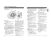
... horizontal rotation, this button is pressed, the value of the white balance or phase adjusted manually is loosened for the camera. Names and Operations of Parts Camera Body Ⅲ Body Surface View when the dome cover is reset to the default value. E-6 • When turning the level (sensitivity adjustment) too far to ...
... horizontal rotation, this button is pressed, the value of the white balance or phase adjusted manually is loosened for the camera. Names and Operations of Parts Camera Body Ⅲ Body Surface View when the dome cover is reset to the default value. E-6 • When turning the level (sensitivity adjustment) too far to ...
Instruction Manual
Page 6
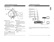
...signal. E-9 English AC24V 1 2 LW40459-001A RED WIRE DC12V + BNC Cable - LOCK VIDEO IN MONITOR Power Unit DC 12 V or AC 24 V TO CAMERA POWER TO CAMERA RX+ RX- DATA I / O UNIT CAMERA COM 1 2 3 4 5 6 7 8 COM 9/1 10/2 11/3 12/4 13/5 14/6 15/7 16/8 COM AUTO ALARM COM SW COM ON OFF...without opening a hole in place. ( ੬ page 12) 5 Cable extraction hole This hole is used to mount the camera body to the ceiling slab or channel. Names and Operations of Parts Camera Body (continued) Ⅲ Body Underside 2 3 1 4 Main unit side 4 5 CLASS 2 ONLY (U TYPE) ISOLATED...
...signal. E-9 English AC24V 1 2 LW40459-001A RED WIRE DC12V + BNC Cable - LOCK VIDEO IN MONITOR Power Unit DC 12 V or AC 24 V TO CAMERA POWER TO CAMERA RX+ RX- DATA I / O UNIT CAMERA COM 1 2 3 4 5 6 7 8 COM 9/1 10/2 11/3 12/4 13/5 14/6 15/7 16/8 COM AUTO ALARM COM SW COM ON OFF...without opening a hole in place. ( ੬ page 12) 5 Cable extraction hole This hole is used to mount the camera body to the ceiling slab or channel. Names and Operations of Parts Camera Body (continued) Ⅲ Body Underside 2 3 1 4 Main unit side 4 5 CLASS 2 ONLY (U TYPE) ISOLATED...
Instruction Manual
Page 7
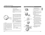
...966;140 4. Drop prevention wire Video signal cable 8. The following : U-type: Class 2 only E-type: Isolated power supply only E-10 Mounting the Camera to the ceiling slab, etc. 6. If voltage drop occurs during operation, the performance will occur when the unit is no need to use a thick... the connection distances and connection cables provided that they do not come into contact with surrounding parts. Connect the video signal cable (BNC connector). MEMO There is at the camera side to below 10%, or place the power supply near to the video signal output connector...
...966;140 4. Drop prevention wire Video signal cable 8. The following : U-type: Class 2 only E-type: Isolated power supply only E-10 Mounting the Camera to the ceiling slab, etc. 6. If voltage drop occurs during operation, the performance will occur when the unit is no need to use a thick... the connection distances and connection cables provided that they do not come into contact with surrounding parts. Connect the video signal cable (BNC connector). MEMO There is at the camera side to below 10%, or place the power supply near to the video signal output connector...
Instruction Manual
Page 8
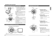
...MANU INT WHT.BAL. Loosen the tilt lock screws. 2. After adjustment is completed, set the FOCUS ADJ. E-13 English E-12 Adjusting the Camera Angle Tilt lock screws Horizontal Lock screw Variable range 120˚ L LEVEIRLIS H MONITOR SERFVOIRCE CORRECSTPIOOTN RESET PHASE R AUTO LL B OFF OFF ... when adjustments are used for Adjustment of the Camera Temporarily used , use the 2 mounting holes to fix the box to the camera body must be adjusted, etc. Screws Mounting holes CAUTION: • Do not hold the lens part when mounting the unit to the ceiling or wall...
...MANU INT WHT.BAL. Loosen the tilt lock screws. 2. After adjustment is completed, set the FOCUS ADJ. E-13 English E-12 Adjusting the Camera Angle Tilt lock screws Horizontal Lock screw Variable range 120˚ L LEVEIRLIS H MONITOR SERFVOIRCE CORRECSTPIOOTN RESET PHASE R AUTO LL B OFF OFF ... when adjustments are used for Adjustment of the Camera Temporarily used , use the 2 mounting holes to fix the box to the camera body must be adjusted, etc. Screws Mounting holes CAUTION: • Do not hold the lens part when mounting the unit to the ceiling or wall...