User Manual
Page 3
... DO NOT OPEN CAUTION: TO REDUCE THE RISK OF ELECTRIC SHOCK, DO NOT REMOVE COVER (OR BACK). NOTE: The rating plate (serial number plate) is on , the user is connected. ● Consult the dealer or an experienced radio/TV technician for radio noise emissions from digital apparatus as set out in accordance with the instructions, may be used with arrowhead...
... DO NOT OPEN CAUTION: TO REDUCE THE RISK OF ELECTRIC SHOCK, DO NOT REMOVE COVER (OR BACK). NOTE: The rating plate (serial number plate) is on , the user is connected. ● Consult the dealer or an experienced radio/TV technician for radio noise emissions from digital apparatus as set out in accordance with the instructions, may be used with arrowhead...
User Manual
Page 4
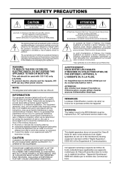
...; DV format High picture and sound quality by digital technology. ● Compatible mechanisms for standard/mini DV cassette tapes It records on and plays back DV cassette tapes of the standard and mini size. (SP mode only) Recording in the DV format can be performed on DVCAM cassette tapes. ● Only PAL/NTSC DVCAM tapes are 3 types of repeat function. (INDEX/ VIDEO END/ TAPE END) ● Recording/playback with an external timer ● With the use of other DV machines, long-time continuous recording is...
...; DV format High picture and sound quality by digital technology. ● Compatible mechanisms for standard/mini DV cassette tapes It records on and plays back DV cassette tapes of the standard and mini size. (SP mode only) Recording in the DV format can be performed on DVCAM cassette tapes. ● Only PAL/NTSC DVCAM tapes are 3 types of repeat function. (INDEX/ VIDEO END/ TAPE END) ● Recording/playback with an external timer ● With the use of other DV machines, long-time continuous recording is...
User Manual
Page 5
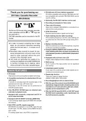
... AND FUNCTIONS OF PARTS Front panel 10 Rear panel 16 ON-SCREEN DISPLAY On-screen display 20 Status display 21 Status/Event display 23 Alarm display 24 LCD display 26 CONNECTION Connecting video signals 28 Connecting audio signals 30 Connecting to editing system 32 Connecting with serial remote terminals ..... 34 Connecting the AC adapter 35 PREPARATION Turning on/off the power 36 Operation method (main unit/remote controller) and operation lock mode 37 Loading/Ejecting cassette 38 Setting the LCD display 39 Setting/Displaying date and time 40 RECORDING Setting 42 Recording...
... AND FUNCTIONS OF PARTS Front panel 10 Rear panel 16 ON-SCREEN DISPLAY On-screen display 20 Status display 21 Status/Event display 23 Alarm display 24 LCD display 26 CONNECTION Connecting video signals 28 Connecting audio signals 30 Connecting to editing system 32 Connecting with serial remote terminals ..... 34 Connecting the AC adapter 35 PREPARATION Turning on/off the power 36 Operation method (main unit/remote controller) and operation lock mode 37 Loading/Ejecting cassette 38 Setting the LCD display 39 Setting/Displaying date and time 40 RECORDING Setting 42 Recording...
User Manual
Page 10
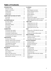
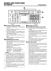
... DV input can be checked. • If this button is pressed during recording, an index signal is turned off the power. (Operate OFF) • OPERATE LED lights up as follows. Front panel - NAMES AND FUNCTIONS OF PARTS 1 - Operate ON : the green LED lights up Operate OFF : the red LED lights up in the AUDIO MENU screen to AUTO or NON DROP, the time code, date and time of time, please remove the AC adapter to turn on the power...
... DV input can be checked. • If this button is pressed during recording, an index signal is turned off the power. (Operate OFF) • OPERATE LED lights up as follows. Front panel - NAMES AND FUNCTIONS OF PARTS 1 - Operate ON : the green LED lights up Operate OFF : the red LED lights up in the AUDIO MENU screen to AUTO or NON DROP, the time code, date and time of time, please remove the AC adapter to turn on the power...

User Manual
Page 13
... : It displays the time code data. If it occurs, set it to select the audio channel for output signals from the headphone terminal and the AUDIO MONITOR terminal located on CTL (control signal). UB : It displays the user's bit (UB). 9 LCD Ⅵ In the playback, still or search mode, it is fixed at channels CH1 and CH2 regardless of the setting of the switch. 7 [AUDIO MONITOR] switch Use this switch and the 6 AUDIO OUTPUT switch are performed in the DISPLAY MENU screen. (☞...
... : It displays the time code data. If it occurs, set it to select the audio channel for output signals from the headphone terminal and the AUDIO MONITOR terminal located on CTL (control signal). UB : It displays the user's bit (UB). 9 LCD Ⅵ In the playback, still or search mode, it is fixed at channels CH1 and CH2 regardless of the setting of the switch. 7 [AUDIO MONITOR] switch Use this switch and the 6 AUDIO OUTPUT switch are performed in the DISPLAY MENU screen. (☞...

User Manual
Page 14
...] button If this button is displayed on the monitor or LCD. During audio dubbing, the audio recording level for connecting to the headphone. (Stereo ø3.5) • When BR-DV6000 plays back tapes recorded in the STOP/STILL mode or when no cassette is loaded, the menu is pressed in the LCD enlarged display mode, the time code preset screen will be displayed on the rear panel cannot be adjusted with the 6 AUDIO OUTPUT switch. @ [PHONES] Headphone volume Use this switch. To input sound from...
...] button If this button is displayed on the monitor or LCD. During audio dubbing, the audio recording level for connecting to the headphone. (Stereo ø3.5) • When BR-DV6000 plays back tapes recorded in the STOP/STILL mode or when no cassette is loaded, the menu is pressed in the LCD enlarged display mode, the time code preset screen will be displayed on the rear panel cannot be adjusted with the 6 AUDIO OUTPUT switch. @ [PHONES] Headphone volume Use this switch. To input sound from...

User Manual
Page 15
... recording pause. (☞ Page 52 "Index search") • When the setting screen is displayed, this button is set to INDEX, press this button to preset the selected time codes or user's bit to start forward index search. This function is not effective during a search operation. (☞ Page 50 "Search mode") If it is used to return to the previous menu or select setting digits. Ⅵ [SET] button • When the Menu screen...
... recording pause. (☞ Page 52 "Index search") • When the setting screen is displayed, this button is set to INDEX, press this button to preset the selected time codes or user's bit to start forward index search. This function is not effective during a search operation. (☞ Page 50 "Search mode") If it is used to return to the previous menu or select setting digits. Ⅵ [SET] button • When the Menu screen...
User Manual
Page 18
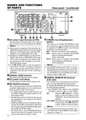
... SYSTEM (2/2) Menu screen is set to "REC" or "PLAY", recording or playback will be input to video equipment with this terminal. (NTSC or PAL) 18 ‹ ) [TIMER] recording/playback switch This switch is for connecting to an external timer. Rear panel - (continued) & VIDEO LINE Y/C COMPONENT IN R-Y B-Y Y OUT REMOTE2 IN OUT AUDIO CH 1/3 CH 2/4 IN MONITOR OUT SIGNAL GND DC12V IN SYNC IN DV IN/OUT OUT TIME CODE IN OUT OFF REC PLAY SERIAL REMOTE TIMER OUT MONITOR OUT...
... SYSTEM (2/2) Menu screen is set to "REC" or "PLAY", recording or playback will be input to video equipment with this terminal. (NTSC or PAL) 18 ‹ ) [TIMER] recording/playback switch This switch is for connecting to an external timer. Rear panel - (continued) & VIDEO LINE Y/C COMPONENT IN R-Y B-Y Y OUT REMOTE2 IN OUT AUDIO CH 1/3 CH 2/4 IN MONITOR OUT SIGNAL GND DC12V IN SYNC IN DV IN/OUT OUT TIME CODE IN OUT OFF REC PLAY SERIAL REMOTE TIMER OUT MONITOR OUT...

User Manual
Page 24
...-SCREEN DISPLAY - OVERHEATING! Consult your JVC-authorized service agent. ● "B" display : Messages for incorrect operation are displayed when the DISPLAY mode is set to record analog signals when PB/DV IN in the LP mode. Data tape for BR- REC INHIBIT (NTSC/PAL) The user attempted to SAVE). It continues to record without DV signal input. The video head is used. Clean it enters the Operate OFF mode. LP TAPE! Display LOW VOLTAGE Description The voltage of the display mode. If the operation...
...-SCREEN DISPLAY - OVERHEATING! Consult your JVC-authorized service agent. ● "B" display : Messages for incorrect operation are displayed when the DISPLAY mode is set to record analog signals when PB/DV IN in the LP mode. Data tape for BR- REC INHIBIT (NTSC/PAL) The user attempted to SAVE). It continues to record without DV signal input. The video head is used. Clean it enters the Operate OFF mode. LP TAPE! Display LOW VOLTAGE Description The voltage of the display mode. If the operation...

User Manual
Page 26
... recording level of BR-DV6000 is -20dB. • For playing a tape recorded with a home-use DV machine with a reference level of -12 dB, set to disappear if it displays the setting status of AUDIO MODE of the AUDIO Menu screen.(48k or 32k) • During playback, the audio mode of the tape is smaller compared with DISPLAY of the AUDIO OUTPUT switch on the LCD of the unit. • Same character display mode as the monitor output • LCD display mode (enlarged display) DISPLAY button Mini MENU...
... recording level of BR-DV6000 is -20dB. • For playing a tape recorded with a home-use DV machine with a reference level of -12 dB, set to disappear if it displays the setting status of AUDIO MODE of the AUDIO Menu screen.(48k or 32k) • During playback, the audio mode of the tape is smaller compared with DISPLAY of the AUDIO OUTPUT switch on the LCD of the unit. • Same character display mode as the monitor output • LCD display mode (enlarged display) DISPLAY button Mini MENU...

User Manual
Page 27
...(2/2) Menu screen is displayed. # Input video signal display Displays the input video signal selected with TCG SOURCE set in the input signal of the Y/C or DV terminal. DUPL : This is displayed when TC DUPLICATE is set up, "- - -" is set to PAL. 5 Time code mode display Displays the time code mode set to EXTERNAL). The time code/user's bit is being played back. @ Time/Date display The data of the VCR. Blinks if the remaining time is displayed as an 8-digit number. 8 VCR mode display Displays the operation mode of the built-in clock will be displayed during playback. Not...
...(2/2) Menu screen is displayed. # Input video signal display Displays the input video signal selected with TCG SOURCE set in the input signal of the Y/C or DV terminal. DUPL : This is displayed when TC DUPLICATE is set up, "- - -" is set to PAL. 5 Time code mode display Displays the time code mode set to EXTERNAL). The time code/user's bit is being played back. @ Time/Date display The data of the VCR. Blinks if the remaining time is displayed as an 8-digit number. 8 VCR mode display Displays the operation mode of the built-in clock will be displayed during playback. Not...
User Manual
Page 33
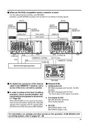
V.SPEED A.SPLIT DURATION PLAYER P EJECT CONTINUE START END V.SPEED EVENT EDITING CONTROL UNIT R M - Monitor Monitor VIDEO MONITOR AUDIO MONITOR VIDEO MONITOR AUDIO MONITOR Player VIDEO OUT AUDIO OUT Video signals Audio signals VIDEO IN AUDIO IN Recorder VIDEO LINE Y/C COMPONENT IN R-Y B-Y Y OUT REMOTE2 IN OUT AUDIO CH 1/3 CH 2/4 IN MONITOR OUT SIGNAL GND DC12V SYNC IN IN DV IN/OUT OUT TIME CODE IN OUT OFF REC PLAY SERIAL REMOTE TIMER OUT MONITOR OUT SYNC IN B.B. G 8 2 0 IN OUT IN OUT P VITC LTC CTL R VITC LTC CTL LAP...
V.SPEED A.SPLIT DURATION PLAYER P EJECT CONTINUE START END V.SPEED EVENT EDITING CONTROL UNIT R M - Monitor Monitor VIDEO MONITOR AUDIO MONITOR VIDEO MONITOR AUDIO MONITOR Player VIDEO OUT AUDIO OUT Video signals Audio signals VIDEO IN AUDIO IN Recorder VIDEO LINE Y/C COMPONENT IN R-Y B-Y Y OUT REMOTE2 IN OUT AUDIO CH 1/3 CH 2/4 IN MONITOR OUT SIGNAL GND DC12V SYNC IN IN DV IN/OUT OUT TIME CODE IN OUT OFF REC PLAY SERIAL REMOTE TIMER OUT MONITOR OUT SYNC IN B.B. G 8 2 0 IN OUT IN OUT P VITC LTC CTL R VITC LTC CTL LAP...

User Manual
Page 35
... (2/2) Menu screen is set to the DC IN terminal. Connecting the AC adapter - Supplied power cord Screw Supplied AC adaptor Clamp DC cord VIDEO LINE Y/C COMPONENT IN R-Y B-Y Y OUT REMOTE2 IN OUT AUDIO CH 1/3 CH 2/4 IN MONITOR OUT SIGNAL GND DC12V SYNC IN IN DV IN/OUT TIME CODE OUT IN OUT OFF REC PLAY SERIAL REMOTE TIMER OUT MONITOR OUT DC IN terminal TIMER switch REMOTE1 OPERATE indicator ONAL DV6000 OPERATE A.DUB REC PLAY PAUSE OPERATE button EJECT REW...
... (2/2) Menu screen is set to the DC IN terminal. Connecting the AC adapter - Supplied power cord Screw Supplied AC adaptor Clamp DC cord VIDEO LINE Y/C COMPONENT IN R-Y B-Y Y OUT REMOTE2 IN OUT AUDIO CH 1/3 CH 2/4 IN MONITOR OUT SIGNAL GND DC12V SYNC IN IN DV IN/OUT TIME CODE OUT IN OUT OFF REC PLAY SERIAL REMOTE TIMER OUT MONITOR OUT DC IN terminal TIMER switch REMOTE1 OPERATE indicator ONAL DV6000 OPERATE A.DUB REC PLAY PAUSE OPERATE button EJECT REW...
User Manual
Page 40
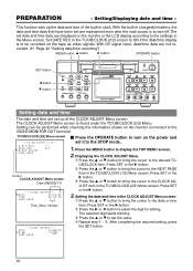
... or time item. PREPARATION - With DV signal input, date/time data are set are displayed on the monitor or the LCD display according to the settings in the TC/UB/CLOCK (2/2) screen to the CLOCK ADJUST item in the TC/UB/CLOCK (1/2) Menu screen. DATE REC OFF CLOCK ADJUST . . Press SET or the : button. 3. Press SET or the : button. 2 Press the : or ; button 9 button Mini MENU DISP RESET SEARCH- Setting can be recorded on the power and set the value. 4 Repeat step 1 - 3. The selected digit starts blinking...
... or time item. PREPARATION - With DV signal input, date/time data are set are displayed on the monitor or the LCD display according to the settings in the TC/UB/CLOCK (2/2) screen to the CLOCK ADJUST item in the TC/UB/CLOCK (1/2) Menu screen. DATE REC OFF CLOCK ADJUST . . Press SET or the : button. 3. Press SET or the : button. 2 Press the : or ; button 9 button Mini MENU DISP RESET SEARCH- Setting can be recorded on the power and set the value. 4 Repeat step 1 - 3. The selected digit starts blinking...

User Manual
Page 56
... button Mini MENU DISP RESET SEARCH- When the power is pressed to change the LCD display to the power output terminal of the external timer. cally. Timer Supplied AC adapter VIDEO LINE Y/C COMPONENT IN R-Y B-Y Y OUT REMOTE2 IN OUT AUDIO CH 1/3 CH 2/4 IN MONITOR OUT SIGNAL GND DC12V IN SYNC IN DV IN/OUT OUT TIME CODE IN OUT OFF REC PLAY SERIAL REMOTE TIMER OUT MONITOR OUT DC IN terminal TIMER switch REMOTE1 Memo Use an...
... button Mini MENU DISP RESET SEARCH- When the power is pressed to change the LCD display to the power output terminal of the external timer. cally. Timer Supplied AC adapter VIDEO LINE Y/C COMPONENT IN R-Y B-Y Y OUT REMOTE2 IN OUT AUDIO CH 1/3 CH 2/4 IN MONITOR OUT SIGNAL GND DC12V IN SYNC IN DV IN/OUT OUT TIME CODE IN OUT OFF REC PLAY SERIAL REMOTE TIMER OUT MONITOR OUT DC IN terminal TIMER switch REMOTE1 Memo Use an...
User Manual
Page 61
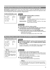
..., set TC DUPLICATE to display the time code on the monitor or the LCD. Insert a tape with a time code reader. ON AUTO OFF :Setting: Ⅵ Set the INPUT SELECT switch on the front panel to DV. Ⅵ Set TC DUPLICATE in the TC/UB/CLOCK(1/2) Menu screen to AUTO. * To record time codes in the STOP mode to NON DROP. Memo Time codes input to the RECORDING mode. ¥ Time codes will be recorded again. 3. The counter mode display shows DTCG or DUBG. 2. Press the PLAY button...
..., set TC DUPLICATE to display the time code on the monitor or the LCD. Insert a tape with a time code reader. ON AUTO OFF :Setting: Ⅵ Set the INPUT SELECT switch on the front panel to DV. Ⅵ Set TC DUPLICATE in the TC/UB/CLOCK(1/2) Menu screen to AUTO. * To record time codes in the STOP mode to NON DROP. Memo Time codes input to the RECORDING mode. ¥ Time codes will be recorded again. 3. The counter mode display shows DTCG or DUBG. 2. Press the PLAY button...

User Manual
Page 62
... digits set the LCD to the enlarged display mode. Ⅵ TC/UB/CLOCK(1/2) Menu screen Set TCG SOURCE to "EXTERNAL". :Operation: 1. After synchronization (slave lock), the internal time code generator continues to run even if external time code signals are recorded on the tape. Set BR-DV6000 to the RECORDING mode. ¥ The EXT display of the LCD lights up and the time code and user's bit of the external time code generator. :Setting: Ⅵ Front switches • Set the INPUT SELECT switch to any setting...
... digits set the LCD to the enlarged display mode. Ⅵ TC/UB/CLOCK(1/2) Menu screen Set TCG SOURCE to "EXTERNAL". :Operation: 1. After synchronization (slave lock), the internal time code generator continues to run even if external time code signals are recorded on the tape. Set BR-DV6000 to the RECORDING mode. ¥ The EXT display of the LCD lights up and the time code and user's bit of the external time code generator. :Setting: Ⅵ Front switches • Set the INPUT SELECT switch to any setting...

User Manual
Page 67
... the JVC bus interface editing controller is used , the monitor output picture of DV interface editing mode to time code information of 7 seconds is set . : -5 frames : ON : PLAYER : LTC Making prerecorded base tape (used for the following situations: • When using perform button on the editing controller. This mode is recommended that will be discontinued when an external sync signal is not input to both the editing recorder, player and the editing controller. •...
... the JVC bus interface editing controller is used , the monitor output picture of DV interface editing mode to time code information of 7 seconds is set . : -5 frames : ON : PLAYER : LTC Making prerecorded base tape (used for the following situations: • When using perform button on the editing controller. This mode is recommended that will be discontinued when an external sync signal is not input to both the editing recorder, player and the editing controller. •...
User Manual
Page 91
... 0 : Playing back LP-mode tape : Always 0 : JVC TABLE 2 enabled : JVC TABLE 1 enabled. : REMOTE switch set as shown in the CTL mode, set , transmit the time data following this command is transmitted before all digits have been transmitted, the time code data are for one's place. 91 Status: If the bit is 1 7 TC GENERATOR : Time code generator in the TCG mode. 6 USER BIT : Counter mode set to the UB mode. 5 TIME CODE : Counter mode set to the TC mode. 4 CONTROL...
... 0 : Playing back LP-mode tape : Always 0 : JVC TABLE 2 enabled : JVC TABLE 1 enabled. : REMOTE switch set as shown in the CTL mode, set , transmit the time data following this command is transmitted before all digits have been transmitted, the time code data are for one's place. 91 Status: If the bit is 1 7 TC GENERATOR : Time code generator in the TCG mode. 6 USER BIT : Counter mode set to the UB mode. 5 TIME CODE : Counter mode set to the TC mode. 4 CONTROL...

User Manual
Page 99
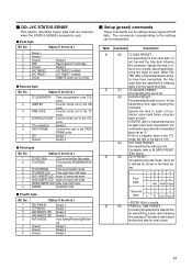
.... Replace the tape. • The head is set to be used. Symptom No power. Set it to "REC" if it is set to OFF? Unable to record. The TIMER switch on the playback video. Action Is the AC adapter correctly connected? Is OPERATION LOCK of BRDV6000 do not work. Serial remote control does not function. Isn't REMOTE SEL DV in the REMOTE (1/2) Menu screen set to REMOTE. Troubleshooting - OTHERS - Isn't REMOTE SEL SER in the REMOTE (1/2) Menu screen set to ALL KEYS? Unable to operate BR...
.... Replace the tape. • The head is set to be used. Symptom No power. Set it to "REC" if it is set to OFF? Unable to record. The TIMER switch on the playback video. Action Is the AC adapter correctly connected? Is OPERATION LOCK of BRDV6000 do not work. Serial remote control does not function. Isn't REMOTE SEL DV in the REMOTE (1/2) Menu screen set to REMOTE. Troubleshooting - OTHERS - Isn't REMOTE SEL SER in the REMOTE (1/2) Menu screen set to ALL KEYS? Unable to operate BR...


