Design Guide
Page 2
The Intel® E7500 chipset MCH may contain design defects or errors known as errata which have no liability whatsoever, and Intel disclaims any express or implied warranty, relating to sale and/or use in the United States and other ...absence or characteristics of any intellectual property rights is provided in Intel's Terms and Conditions of Intel Corporation or its subsidiaries in medical, life saving, or life sustaining applications. Copyright © 2002 Intel Corporation 2 Intel® E7500 MCH Thermal and Mechanical Design Guidelines No license, express or implied...
The Intel® E7500 chipset MCH may contain design defects or errors known as errata which have no liability whatsoever, and Intel disclaims any express or implied warranty, relating to sale and/or use in the United States and other ...absence or characteristics of any intellectual property rights is provided in Intel's Terms and Conditions of Intel Corporation or its subsidiaries in medical, life saving, or life sustaining applications. Copyright © 2002 Intel Corporation 2 Intel® E7500 MCH Thermal and Mechanical Design Guidelines No license, express or implied...
Design Guide
Page 7
...and specifications for the MCH component only. Care must be expected to provide an understanding of the operating limits of the Intel® E7500 chipset MCH and describe a reference thermal solution. This is accomplished by providing a low local-ambient temperature, ensuring adequate local ...solutions provide adequate cooling to balance size and space constraints with system thermal solutions. For thermal design information on other chipset components, refer to the Intel® PCI/PCI-X 64-bit Hub 2 (P64H2) Thermal and Mechanical Design Guidelines. Heat can be dissipated using...
...and specifications for the MCH component only. Care must be expected to provide an understanding of the operating limits of the Intel® E7500 chipset MCH and describe a reference thermal solution. This is accomplished by providing a low local-ambient temperature, ensuring adequate local ...solutions provide adequate cooling to balance size and space constraints with system thermal solutions. For thermal design information on other chipset components, refer to the Intel® PCI/PCI-X 64-bit Hub 2 (P64H2) Thermal and Mechanical Design Guidelines. Heat can be dissipated using...
Design Guide
Page 9
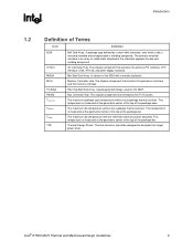
...center of the top of the package die. Introduction R 1.2 Definition of the package case. The chipset component that interfaces the PCI-X buses. The chipset component that contains the processor interface and the memory interface. The maximum die temperature without any package ...thermal solution. The chipset component that contains the primary PCI interface, LPC interface, USB, ATA-33, and other legacy functions. This temperature is mounted, bonded and encapsulated in molding compound. Intel® E7500 MCH Thermal and Mechanical Design Guidelines 9...
...center of the top of the package die. Introduction R 1.2 Definition of the package case. The chipset component that interfaces the PCI-X buses. The chipset component that contains the processor interface and the memory interface. The maximum die temperature without any package ...thermal solution. The chipset component that contains the primary PCI interface, LPC interface, USB, ATA-33, and other legacy functions. This temperature is mounted, bonded and encapsulated in molding compound. Intel® E7500 MCH Thermal and Mechanical Design Guidelines 9...
Design Guide
Page 10
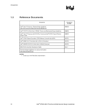
...; PCI/PCI-X 64-bit Hub 2 (P64H2) Thermal and Mechanical Design Guidelines Intel® Xeon™ Processor with 512 KB L2 Cache and Intel® E7500 Chipset Platform Design Guide Intel® E7500 Chipset Datasheet: E7500 Memory Controller Hub (MCH) Intel® 82801CA I/O Controller Hub 3 (ICH3-S) Datasheet Intel® 82870P2 PCI/PCI-X 64-bit Hub 2 (P64H2) Datasheet BGA/OLGA Assembly Development...
...; PCI/PCI-X 64-bit Hub 2 (P64H2) Thermal and Mechanical Design Guidelines Intel® Xeon™ Processor with 512 KB L2 Cache and Intel® E7500 Chipset Platform Design Guide Intel® E7500 Chipset Datasheet: E7500 Memory Controller Hub (MCH) Intel® 82801CA I/O Controller Hub 3 (ICH3-S) Datasheet Intel® 82870P2 PCI/PCI-X 64-bit Hub 2 (P64H2) Datasheet BGA/OLGA Assembly Development...

Design Guide
Page 11
...11 For information on the ICH3-S package, refer to the Intel® 82801CA I/O Controller Hub 3 (ICH3-S) Datasheet. Figure 2. Packaging Technology R 2 Packaging Technology The E7500 chipset consists of the solder balls. 4. The E7500 MCH utilizes a 42.5 mm, 6-layer FC-BGA package ...shown in millimeters. 2. All dimensions and tolerances conform to the Intel® 82870P2 PCI/PCI-X 64-bit Hub 2 (P64H2...
...11 For information on the ICH3-S package, refer to the Intel® 82801CA I/O Controller Hub 3 (ICH3-S) Datasheet. Figure 2. Packaging Technology R 2 Packaging Technology The E7500 chipset consists of the solder balls. 4. The E7500 MCH utilizes a 42.5 mm, 6-layer FC-BGA package ...shown in millimeters. 2. All dimensions and tolerances conform to the Intel® 82870P2 PCI/PCI-X 64-bit Hub 2 (P64H2...
Design Guide
Page 15
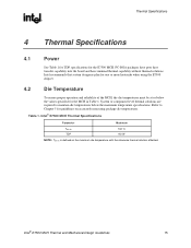
... temperature with the reference thermal solution attached. Intel recommends that system designers plan for the MCH in Table 1. Refer to maintain die temperatures below the values specified for one or more heatsinks when using the E7500 chipset. 4.2 Die Temperature To ensure proper operation ...and reliability of the MCH, the die temperatures must be at or below the maximum temperature specifications. Intel® E7500 MCH Thermal and Mechanical Design Guidelines 15 System ...
... temperature with the reference thermal solution attached. Intel recommends that system designers plan for the MCH in Table 1. Refer to maintain die temperatures below the values specified for one or more heatsinks when using the E7500 chipset. 4.2 Die Temperature To ensure proper operation ...and reliability of the MCH, the die temperatures must be at or below the maximum temperature specifications. Intel® E7500 MCH Thermal and Mechanical Design Guidelines 15 System ...
Design Guide
Page 20
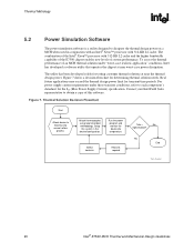
... limit for determining thermal solution needs. Setup the system in conjunction with an Intel® Xeon™ processor with 512-KB L2 cache and the higher bandwidth capability of the E7500 chipset enables new levels of this software. Contact your Intel Field Sales representative to board using normal reflow process Attach thermocouples using recommended...
... limit for determining thermal solution needs. Setup the system in conjunction with an Intel® Xeon™ processor with 512-KB L2 cache and the higher bandwidth capability of the E7500 chipset enables new levels of this software. Contact your Intel Field Sales representative to board using normal reflow process Attach thermocouples using recommended...
Design Guide
Page 21
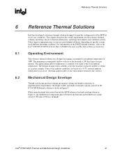
...local-ambient operating conditions. The approaching airflow temperature is 200 lfm (linear feet per minute). Intel® E7500 MCH Thermal and Mechanical Design Guidelines 21 Other chipset components may or may have unique mechanical volume and height restrictions or implementation requirements, the height,... width, and depth constraints typically placed on the E7500 MCH thermal solution is shown in height....
...local-ambient operating conditions. The approaching airflow temperature is 200 lfm (linear feet per minute). Intel® E7500 MCH Thermal and Mechanical Design Guidelines 21 Other chipset components may or may have unique mechanical volume and height restrictions or implementation requirements, the height,... width, and depth constraints typically placed on the E7500 MCH thermal solution is shown in height....
Design Guide
Page 26
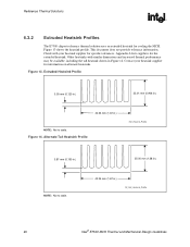
Reference Thermal Solutions R 6.3.2 Extruded Heatsink Profiles The E7500 chipset reference thermal solution uses an extruded heatsink for the extruded heatsink. Figure 13. Alternate Tall Heatsink Profile Extr_Heasink_Profile 3.81 mm (0.150 in.) NOTE: Not to .... Figure 13 shows the heatsink profile. Check with similar dimensions and increased thermal performance may be available, including the tall heatsink shown in .) Alt_Extr_Heatsink_Profile 26 Intel® E7500 MCH Thermal and Mechanical Design Guidelines
Reference Thermal Solutions R 6.3.2 Extruded Heatsink Profiles The E7500 chipset reference thermal solution uses an extruded heatsink for the extruded heatsink. Figure 13. Alternate Tall Heatsink Profile Extr_Heasink_Profile 3.81 mm (0.150 in.) NOTE: Not to .... Figure 13 shows the heatsink profile. Check with similar dimensions and increased thermal performance may be available, including the tall heatsink shown in .) Alt_Extr_Heatsink_Profile 26 Intel® E7500 MCH Thermal and Mechanical Design Guidelines
Design Guide
Page 28
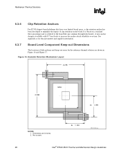
... Figure 16 and Figure 17. A new anchor design is soldered to increase the anchor attach reliability over time. Reference Thermal Solutions R 6.3.6 Clip Retention Anchors For E7500 chipset-based platforms that have very limited board space, a clip retention anchor has been developed to scale. 2x 1.109 850_Anchor_Lay 28...
... Figure 16 and Figure 17. A new anchor design is soldered to increase the anchor attach reliability over time. Reference Thermal Solutions R 6.3.6 Clip Retention Anchors For E7500 chipset-based platforms that have very limited board space, a clip retention anchor has been developed to scale. 2x 1.109 850_Anchor_Lay 28...
