
DG965MQ Technical Product Specification
Page 6
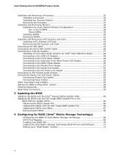
...72 3.3.2 PCI IDE Support 73 3.4 System Management BIOS (SMBIOS 73 3.5 Legacy USB Support 74 3.6 BIOS Updates 74 3.6.1 Language Support 75 3.6.2 Custom Splash Screen 75 3.7 BIOS Recovery 75 3.8 Boot Options 76 3.8.1 CD-ROM Boot 76 3.8.2 Network Boot 76 3.8.3 Booting Without Attached Devices 76 3.8.4 Changing the Default Boot Device During POST 76 3.9 Adjusting Boot Speed 77 3.9.1 Peripheral Selection and Configuration 77 3.9.2 BIOS Boot Optimizations 77 3.10 BIOS Security Features 78 4 Error Messages and Beep Codes 4.1 Speaker 79 4.2 BIOS Beep Codes 79 4.3 BIOS Error Messages...
...72 3.3.2 PCI IDE Support 73 3.4 System Management BIOS (SMBIOS 73 3.5 Legacy USB Support 74 3.6 BIOS Updates 74 3.6.1 Language Support 75 3.6.2 Custom Splash Screen 75 3.7 BIOS Recovery 75 3.8 Boot Options 76 3.8.1 CD-ROM Boot 76 3.8.2 Network Boot 76 3.8.3 Booting Without Attached Devices 76 3.8.4 Changing the Default Boot Device During POST 76 3.9 Adjusting Boot Speed 77 3.9.1 Peripheral Selection and Configuration 77 3.9.2 BIOS Boot Optimizations 77 3.10 BIOS Security Features 78 4 Error Messages and Beep Codes 4.1 Speaker 79 4.2 BIOS Beep Codes 79 4.3 BIOS Error Messages...
DG965MQ Technical Product Specification
Page 7
.... Connection Diagram for Front Panel Header 58 18. Board Dimensions 62 22. Effects of the Jumper Block 61 21. Front/Back Panel Audio Connector Options 31 11. LAN Connector LED Locations 33 12. Board Components Shown in Figure 1 13 4. Audio Jack Retasking Support 30 8. Detailed System Memory Address Map 44 15. Feature Summary 10 2. Supported Memory Configurations 16 5. I /O Shield Dimensions for Front Panel USB Headers 60 19. Connection Diagram for Boards with Four DIMMs 20 7. Flex Mode Configuration with...
.... Connection Diagram for Front Panel Header 58 18. Board Dimensions 62 22. Effects of the Jumper Block 61 21. Front/Back Panel Audio Connector Options 31 11. LAN Connector LED Locations 33 12. Board Components Shown in Figure 1 13 4. Audio Jack Retasking Support 30 8. Detailed System Memory Address Map 44 15. Feature Summary 10 2. Supported Memory Configurations 16 5. I /O Shield Dimensions for Front Panel USB Headers 60 19. Connection Diagram for Boards with Four DIMMs 20 7. Flex Mode Configuration with...

DG965MQ Technical Product Specification
Page 8
... 17. Serial ATA Connectors 54 21. Serial Port Header 54 23. Processor Fan Header 55 26. Auxiliary Front Panel Power LED Header 59 33. BIOS Setup Program Menu Bar 72 39. I/O Map 46 15. PCI Configuration Space Map 47 16. BIOS Setup Program Function Keys 72 40. Main Power Connector 57 29. Front Panel Header 58 30. DC Loading Characteristics 65 35. Boot Device Menu Options 76 42. Front and Rear Chassis Fan Headers 55 25. States for Components 69 37. Beep Codes 79 44...
... 17. Serial ATA Connectors 54 21. Serial Port Header 54 23. Processor Fan Header 55 26. Auxiliary Front Panel Power LED Header 59 33. BIOS Setup Program Menu Bar 72 39. I/O Map 46 15. PCI Configuration Space Map 47 16. BIOS Setup Program Function Keys 72 40. Main Power Connector 57 29. Front Panel Header 58 30. DC Loading Characteristics 65 35. Boot Device Menu Options 76 42. Front and Rear Chassis Fan Headers 55 25. States for Components 69 37. Beep Codes 79 44...
DG965MQ Technical Product Specification
Page 10
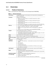
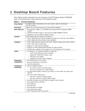
...Intel Desktop Board DG965MQ Technical Product Specification 1.1 Overview 1.1.1 Feature Summary Table 1 summarizes the major features of : • Intel® 82G965 Graphics Memory Controller Hub (GMCH) • Intel® 82801 I/O Controller Hub (ICH8). Feature Summary Form Factor Processor Memory Chipset Video Audio Legacy I /O controller for diskette drive, serial, parallel, and optional PS/2* ports USB Peripheral Interfaces LAN Support BIOS Instantly Available PC Technology Support for USB 2.0 devices • 10 USB ports • Two IEEE-1394a interfaces: one back panel connector...
...Intel Desktop Board DG965MQ Technical Product Specification 1.1 Overview 1.1.1 Feature Summary Table 1 summarizes the major features of : • Intel® 82G965 Graphics Memory Controller Hub (GMCH) • Intel® 82801 I/O Controller Hub (ICH8). Feature Summary Form Factor Processor Memory Chipset Video Audio Legacy I /O controller for diskette drive, serial, parallel, and optional PS/2* ports USB Peripheral Interfaces LAN Support BIOS Instantly Available PC Technology Support for USB 2.0 devices • 10 USB ports • Two IEEE-1394a interfaces: one back panel connector...
DG965MQ Technical Product Specification
Page 16
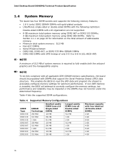
... structure. If non-SPD memory is required to fully enable both the onboard graphics and the manageability engine. NOTE To be fully compliant with all applicable DDR SDRAM memory specifications, the board should be impacted or the DIMMs may not function under the determined frequency. Intel Desktop Board DG965MQ Technical Product Specification 1.4 System Memory The board has four DIMM sockets and supports the following memory features: • 1.8 V (only...
... structure. If non-SPD memory is required to fully enable both the onboard graphics and the manageability engine. NOTE To be fully compliant with all applicable DDR SDRAM memory specifications, the board should be impacted or the DIMMs may not function under the determined frequency. Intel Desktop Board DG965MQ Technical Product Specification 1.4 System Memory The board has four DIMM sockets and supports the following memory features: • 1.8 V (only...
DG965MQ Technical Product Specification
Page 25
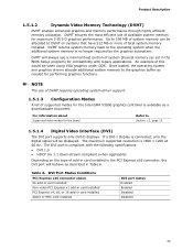
... as set in card installed ADD2 or MEC card installed DVI port status Enabled Enabled Disabled Disabled 25 Product Description 1.5.1.2 Dynamic Video Memory Technology (DVMT) DVMT enables enhanced graphics and memory performance through highly efficient memory utilization. An example of available system memory for the Intel GMA X3000 graphics controller is compliant with legacy applications. DVI Port Status Conditions PCI Express x16 connector status No add-in card installed Non-video PCI Express x1 add-in card installed PCI Express x4, x8, or 16 add-in the BIOS Setup...
... as set in card installed ADD2 or MEC card installed DVI port status Enabled Enabled Disabled Disabled 25 Product Description 1.5.1.2 Dynamic Video Memory Technology (DVMT) DVMT enables enhanced graphics and memory performance through highly efficient memory utilization. An example of available system memory for the Intel GMA X3000 graphics controller is compliant with legacy applications. DVI Port Status Conditions PCI Express x16 connector status No add-in card installed Non-video PCI Express x1 add-in card installed PCI Express x4, x8, or 16 add-in the BIOS Setup...
DG965MQ Technical Product Specification
Page 71
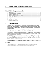
... system boot begins. When the BIOS Setup configuration jumper is set to put the board in configure mode. Maintenance Main Advanced Security Power Boot Exit NOTE The maintenance menu is displayed only when the board is shown below. The BIOS displays a message during POST identifying the type of BIOS Features What This Chapter Contains 3.1 Introduction 71 3.2 BIOS Flash Memory Organization 72 3.3 Resource Configuration 72 3.4 System Management BIOS (SMBIOS 73 3.5 Legacy USB Support 74 3.6 BIOS Updates 74 3.7 BIOS Recovery 75 3.8 Boot Options 76 3.9 Adjusting Boot Speed 77...
... system boot begins. When the BIOS Setup configuration jumper is set to put the board in configure mode. Maintenance Main Advanced Security Power Boot Exit NOTE The maintenance menu is displayed only when the board is shown below. The BIOS displays a message during POST identifying the type of BIOS Features What This Chapter Contains 3.1 Introduction 71 3.2 BIOS Flash Memory Organization 72 3.3 Resource Configuration 72 3.4 System Management BIOS (SMBIOS 73 3.5 Legacy USB Support 74 3.6 BIOS Updates 74 3.7 BIOS Recovery 75 3.8 Boot Options 76 3.9 Adjusting Boot Speed 77...
DG965MQ Technical Product Specification
Page 72
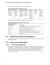
... Configuration 3.3.1 PCI Autoconfiguration The BIOS can automatically configure PCI devices. When a user turns on the system after adding a PCI card, the BIOS automatically configures interrupts, the I/O space, and other system resources. BIOS Setup Program Menu Bar Maintenance Main Advanced Security Clears passwords and displays processor information Displays processor and memory configuration Configures advanced features available through the chipset Sets passwords and security features Power Configures power management features and power supply controls Boot Selects boot options...
... Configuration 3.3.1 PCI Autoconfiguration The BIOS can automatically configure PCI devices. When a user turns on the system after adding a PCI card, the BIOS automatically configures interrupts, the I/O space, and other system resources. BIOS Setup Program Menu Bar Maintenance Main Advanced Security Clears passwords and displays processor information Displays processor and memory configuration Configures advanced features available through the chipset Sets passwords and security features Power Configures power management features and power supply controls Boot Selects boot options...
DG965MQ Technical Product Specification
Page 73
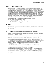
... configures them to ATA-66/100/133 and recognizes any ATAPI compliant devices, including CD-ROM drives, tape drives, and Ultra DMA drives. The IDE interface supports hard drives up the PCI IDE connector with independent I/O channel support. Using SMBIOS, a system administrator can override the auto-configuration options by specifying manual configuration in the BIOS Setup program, the BIOS automatically sets up to optimize capacity and performance. Overview of BIOS Features 3.3.2 PCI IDE Support If you select Auto in the BIOS Setup...
... configures them to ATA-66/100/133 and recognizes any ATAPI compliant devices, including CD-ROM drives, tape drives, and Ultra DMA drives. The IDE interface supports hard drives up the PCI IDE connector with independent I/O channel support. Using SMBIOS, a system administrator can override the auto-configuration options by specifying manual configuration in the BIOS Setup program, the BIOS automatically sets up to optimize capacity and performance. Overview of BIOS Features 3.3.2 PCI IDE Support If you select Auto in the BIOS Setup...

DG965MQ Technical Product Specification
Page 80
..., all POST codes and range values are listed in card, often called a POST card. D0 - Intel Desktop Board DG965MQ Technical Product Specification 4.4 Port 80h POST Codes During the POST, the BIOS generates diagnostic progress codes (POST-codes) to I /O Busses: PCI, USB, ISA, ATA, etc. 5F is an unrecoverable error. Start with PCI. 60 - 6F Reserved for future use (for future use . 50 - 5F I /O port 80h. B0 - This code is no memory detected or no useful memory detected. 30 - 3F Recovery: 3F indicated recovery failure...
..., all POST codes and range values are listed in card, often called a POST card. D0 - Intel Desktop Board DG965MQ Technical Product Specification 4.4 Port 80h POST Codes During the POST, the BIOS generates diagnostic progress codes (POST-codes) to I /O Busses: PCI, USB, ISA, ATA, etc. 5F is an unrecoverable error. Start with PCI. 60 - 6F Reserved for future use (for future use . 50 - 5F I /O port 80h. B0 - This code is no memory detected or no useful memory detected. 30 - 3F Recovery: 3F indicated recovery failure...

DG965MQ Technical Product Specification
Page 81
... Hot Plug PCI controller initialization Reserved for PCI Bus USB 58 Resetting USB bus 59 Reserved for USB ATA/ATAPI/SATA 5A Resetting PATA/SATA bus and all devices 5B Reserved for ATA SMBus 5C Resetting SMBUS 5D Reserved for SMBUS Local Console 70 Resetting the VGA controller 71 Disabling the VGA controller 72 Enabling the VGA controller Remote Console 78 Resetting the console controller 79 Disabling the console controller 7A Enabling the console controller continued 81 Error Messages and Beep Codes Table 46...
... Hot Plug PCI controller initialization Reserved for PCI Bus USB 58 Resetting USB bus 59 Reserved for USB ATA/ATAPI/SATA 5A Resetting PATA/SATA bus and all devices 5B Reserved for ATA SMBus 5C Resetting SMBUS 5D Reserved for SMBUS Local Console 70 Resetting the VGA controller 71 Disabling the VGA controller 72 Enabling the VGA controller Remote Console 78 Resetting the console controller 79 Disabling the console controller 7A Enabling the console controller continued 81 Error Messages and Beep Codes Table 46...

DG965MQ Technical Product Specification
Page 83
Error Messages and Beep Codes Table 46. Port 80h POST Codes (continued) POST Code Description of POST Operation DXE Drivers E7 Waiting for user input E8 Checking password E9 Entering BIOS setup EB Calling Legacy Option ROMs Runtime Phase/EFI OS Boot F4 Entering Sleep state F5 Exiting Sleep state F8 EFI boot service ExitBootServices ( ) has been called F9 EFI runtime service SetVirtualAddressMap ( ) has been called FA EFI runtime service ResetSystem ( ) has been called PEIMs/Recovery 30 Crisis...
Error Messages and Beep Codes Table 46. Port 80h POST Codes (continued) POST Code Description of POST Operation DXE Drivers E7 Waiting for user input E8 Checking password E9 Entering BIOS setup EB Calling Legacy Option ROMs Runtime Phase/EFI OS Boot F4 Entering Sleep state F5 Exiting Sleep state F8 EFI boot service ExitBootServices ( ) has been called F9 EFI runtime service SetVirtualAddressMap ( ) has been called FA EFI runtime service ResetSystem ( ) has been called PEIMs/Recovery 30 Crisis...

DG965MQ Desktop Board Specification Update
Page 6
... 1.8.1 Intel® 82566DC Gigabit Ethernet Controller. Changes to Section 1.7.2 Audio Connectors. The following note will be added to the Technical Product Specification in a future revision of the desktop board, and to account for this erratum. Frontpanel connectors should provide sufficient protection to prevent ESD damage to fix this product Specification Changes 1. The following notations are used in a future revision of the desktop board, driver, or BIOS...
... 1.8.1 Intel® 82566DC Gigabit Ethernet Controller. Changes to Section 1.7.2 Audio Connectors. The following note will be added to the Technical Product Specification in a future revision of the desktop board, and to account for this erratum. Frontpanel connectors should provide sufficient protection to prevent ESD damage to fix this product Specification Changes 1. The following notations are used in a future revision of the desktop board, driver, or BIOS...
English Product Guide
Page 3
... used in homes, offices, schools, computer rooms, and similar locations. may not be supported without further evaluation by Intel. NOTE Notes call attention to hardware or loss of product features 2 Installing and Replacing Desktop Board Components: instructions on how to install the desktop board and other hardware components 3 Updating the BIOS: instructions on how to update the BIOS 4 Configuring for RAID (Intel® Matrix Storage Technology): information about configuring your system for Intel® Desktop Board DG965MQ...
... used in homes, offices, schools, computer rooms, and similar locations. may not be supported without further evaluation by Intel. NOTE Notes call attention to hardware or loss of product features 2 Installing and Replacing Desktop Board Components: instructions on how to install the desktop board and other hardware components 3 Updating the BIOS: instructions on how to update the BIOS 4 Configuring for RAID (Intel® Matrix Storage Technology): information about configuring your system for Intel® Desktop Board DG965MQ...
English Product Guide
Page 6
... the BIOS Configuration Jumper 56 Clearing Passwords 58 Back Panel Connectors 59 3 Updating the BIOS Updating the BIOS with the Intel® Express BIOS Update Utility 65 Updating the BIOS with the ISO Image BIOS Update File or the Iflash Memory Update Utility 66 Obtaining the BIOS Update File 66 Updating the BIOS with the ISO Image BIOS Update File 66 Updating the BIOS with Iflash 67 Recovering the BIOS 68 4 Configuring for RAID (Intel® Matrix Storage Technology) Configuring the BIOS for Intel Matrix Storage Technology 69 SATA Port Mapping 69 Creating Your RAID Set 70 Loading...
... the BIOS Configuration Jumper 56 Clearing Passwords 58 Back Panel Connectors 59 3 Updating the BIOS Updating the BIOS with the Intel® Express BIOS Update Utility 65 Updating the BIOS with the ISO Image BIOS Update File or the Iflash Memory Update Utility 66 Obtaining the BIOS Update File 66 Updating the BIOS with the ISO Image BIOS Update File 66 Updating the BIOS with Iflash 67 Recovering the BIOS 68 4 Configuring for RAID (Intel® Matrix Storage Technology) Configuring the BIOS for Intel Matrix Storage Technology 69 SATA Port Mapping 69 Creating Your RAID Set 70 Loading...
English Product Guide
Page 9
... • Intel® Clear Video Technology • Support for VGA and DVI displays • Support for Dual-Independent Display via VGA and DVI • PCI Express* graphics card support via a PCI Express x16 connector • 8-channel (7.1) onboard subsystem, featuring: ― Intel® High Definition Audio interface ― SigmaTel* STAC9271D audio codec ― HD Audio Link header ― Support for up to a IEEE 1394a header • One IDE interface with ATA-66/100 support (two devices) • One diskette drive interface • One VGA port •...
... • Intel® Clear Video Technology • Support for VGA and DVI displays • Support for Dual-Independent Display via VGA and DVI • PCI Express* graphics card support via a PCI Express x16 connector • 8-channel (7.1) onboard subsystem, featuring: ― Intel® High Definition Audio interface ― SigmaTel* STAC9271D audio codec ― HD Audio Link header ― Support for up to a IEEE 1394a header • One IDE interface with ATA-66/100 support (two devices) • One diskette drive interface • One VGA port •...
English Product Guide
Page 12
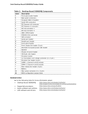
... PCI Express x16 connector PCI Express x1 connector PCI bus connector 1 PCI bus connector 2 IEEE 1394a header Diskette drive connector IDE connector Serial port header Parallel port header Front panel header Front chassis fan header (3-pin) Alternate front panel power LED header Speaker Chassis intrusion header HD Audio Link header Processor socket 12 V processor core voltage connector (2 x 2 pin ) Processor fan header (4-pin) DIMM 1, Channel A and B sockets DIMM 0, Channel A and B sockets Rear chassis fan header (3-pin) Battery Main power connector (2 x 12 pin) BIOS configuration jumper...
... PCI Express x16 connector PCI Express x1 connector PCI bus connector 1 PCI bus connector 2 IEEE 1394a header Diskette drive connector IDE connector Serial port header Parallel port header Front panel header Front chassis fan header (3-pin) Alternate front panel power LED header Speaker Chassis intrusion header HD Audio Link header Processor socket 12 V processor core voltage connector (2 x 2 pin ) Processor fan header (4-pin) DIMM 1, Channel A and B sockets DIMM 0, Channel A and B sockets Rear chassis fan header (3-pin) Battery Main power connector (2 x 12 pin) BIOS configuration jumper...
English Product Guide
Page 19
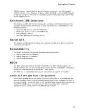
... PCI/PCI Express and IDE auto-configuration utilities, and the video BIOS. This may be updated by specifying manual configuration in the BIOS Setup program. 19 The BIOS is stored in the BIOS reverts all USB 2.0 ports to two IDE devices (such as hard drives) • ATAPI-style devices (such as hard disk drives and CD-ROM drives. Desktop Board Features USB 2.0 support requires both an operating system and drivers that do not need to run the BIOS Setup program after installing a Serial ATA or IDE device. Disabling Hi-Speed USB in a Serial...
... PCI/PCI Express and IDE auto-configuration utilities, and the video BIOS. This may be updated by specifying manual configuration in the BIOS Setup program. 19 The BIOS is stored in the BIOS reverts all USB 2.0 ports to two IDE devices (such as hard drives) • ATAPI-style devices (such as hard disk drives and CD-ROM drives. Desktop Board Features USB 2.0 support requires both an operating system and drivers that do not need to run the BIOS Setup program after installing a Serial ATA or IDE device. Disabling Hi-Speed USB in a Serial...
English Product Guide
Page 70
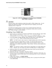
... the RAID LEVEL. Intel Desktop Board DG965MQ Product Guide Figure 34. In the Intel Matrix Storage Manager option ROM Main Menu, select option #1: Create RAID Volume. The SATA port mapping shown in the Intel® Matrix Storage Configuration Utility (Ctrl+I) and the Intel® Matrix Storage Console software. Enter the size of the volume (if you enter less than one RAID array on the screen: Press to enter the RAID Configuration Utility. Exit the Option ROM user interface by pressing or going to Create Volume. 8. SATA Port...
... the RAID LEVEL. Intel Desktop Board DG965MQ Product Guide Figure 34. In the Intel Matrix Storage Manager option ROM Main Menu, select option #1: Create RAID Volume. The SATA port mapping shown in the Intel® Matrix Storage Configuration Utility (Ctrl+I) and the Intel® Matrix Storage Console software. Enter the size of the volume (if you enter less than one RAID array on the screen: Press to enter the RAID Configuration Utility. Exit the Option ROM user interface by pressing or going to Create Volume. 8. SATA Port...

English Product Guide
Page 71
... to update to manage the RAID configuration. Install the Intel® ICH8R/DO/DH SATA RAID Controller (Desktop ICH8R) driver. 3. Begin Windows Setup by booting from this section: "Configuring the BIOS for Intel Matrix Storage Technology" and "Loading the Intel Matrix Storage Technology RAID Drivers and Software". Updating the BIOS Loading the Intel Matrix Storage Technology RAID Drivers and Software 1. Install the Intel Matrix Storage Console software via the Intel Express Installer CD included with your desktop board or after downloading it from a single Serial ATA drive to RAID...
... to update to manage the RAID configuration. Install the Intel® ICH8R/DO/DH SATA RAID Controller (Desktop ICH8R) driver. 3. Begin Windows Setup by booting from this section: "Configuring the BIOS for Intel Matrix Storage Technology" and "Loading the Intel Matrix Storage Technology RAID Drivers and Software". Updating the BIOS Loading the Intel Matrix Storage Technology RAID Drivers and Software 1. Install the Intel Matrix Storage Console software via the Intel Express Installer CD included with your desktop board or after downloading it from a single Serial ATA drive to RAID...


