
DB65AL Technical Product Specification
Page 8
Intel Desktop Board DB65AL Technical Product Specification 1.16 Intel Standard Manageability Technology 30 1.16.1 Intel Standard Manageability Features 30 1.16.2 Intel® Active Management Technology Software and Drivers....... 32 1.17 Power Management 32 1.17.1 ACPI 33 1.17.2 Hardware Support 36 2 Technical Reference 2.1 Memory Resources 41 2.1.1 Addressable Memory 41 2.1.2 Memory Map 43 2.2 Connectors and Headers 43 2.2.1 Back Panel Connectors 44 2.2.2 Component-side Connectors and Headers 45 2.3 BIOS Configuration Jumper Block 54 2.4 Intel® Management Engine BIOS ...
Intel Desktop Board DB65AL Technical Product Specification 1.16 Intel Standard Manageability Technology 30 1.16.1 Intel Standard Manageability Features 30 1.16.2 Intel® Active Management Technology Software and Drivers....... 32 1.17 Power Management 32 1.17.1 ACPI 33 1.17.2 Hardware Support 36 2 Technical Reference 2.1 Memory Resources 41 2.1.1 Addressable Memory 41 2.1.2 Memory Map 43 2.2 Connectors and Headers 43 2.2.1 Back Panel Connectors 44 2.2.2 Component-side Connectors and Headers 45 2.3 BIOS Configuration Jumper Block 54 2.4 Intel® Management Engine BIOS ...
DB65AL Technical Product Specification
Page 9
...-side Connectors and Headers 45 103H 293H 11. Board Dimensions 57 108H 298H 16. LAN Connector LED Locations 26 98H 28H 6. Localized High Temperature Zones 61 109H 29H Tables 1. LAN Connector LED States 26 13H 30H 5. System Memory Map 43 17H 307H 9. Location of Pressing the Power Switch 33 14H 304H 6. Feature Summary 11 10H 30H 2. Thermal Sensors and Fan Headers 28 9H 289H 7. Supported Memory Configurations 18 12H 302H 4. Wake-up Devices...
...-side Connectors and Headers 45 103H 293H 11. Board Dimensions 57 108H 298H 16. LAN Connector LED Locations 26 98H 28H 6. Localized High Temperature Zones 61 109H 29H Tables 1. LAN Connector LED States 26 13H 30H 5. System Memory Map 43 17H 307H 9. Location of Pressing the Power Switch 33 14H 304H 6. Feature Summary 11 10H 30H 2. Thermal Sensors and Fan Headers 28 9H 289H 7. Supported Memory Configurations 18 12H 302H 4. Wake-up Devices...
DB65AL Technical Product Specification
Page 10
.... Processor (4-Pin) Fan Header 49 19. Main Power Connector 50 23. Recommended Power Supply Current Values 58 29. Environmental Specifications 62 32. Boot Device Menu Options 68 36. EMC Regulations 85 46. Port 80h POST Codes 76 43. S/PDIF Header 47 12. Front Panel USB Header 48 16. Processor Core Power Connector 50 22. States for AC '97 Audio 48 15. BIOS Beep Codes 73 39. Regulatory Compliance Marks 89 345H x Intel Desktop Board DB65AL Technical Product Specification 10. Intel MEBX Reset Header Signals 56 28. Front-panel Power LED...
.... Processor (4-Pin) Fan Header 49 19. Main Power Connector 50 23. Recommended Power Supply Current Values 58 29. Environmental Specifications 62 32. Boot Device Menu Options 68 36. EMC Regulations 85 46. Port 80h POST Codes 76 43. S/PDIF Header 47 12. Front Panel USB Header 48 16. Processor Core Power Connector 50 22. States for AC '97 Audio 48 15. BIOS Beep Codes 73 39. Regulatory Compliance Marks 89 345H x Intel Desktop Board DB65AL Technical Product Specification 10. Intel MEBX Reset Header Signals 56 28. Front-panel Power LED...

DB65AL Technical Product Specification
Page 14
... O Serial port header P Battery Q Chassis intrusion header R Front chassis fan header S Main power connector (2 x 12) T Standby power LED U Piezoelectric speaker V Intel B65 Express Chipset W Alternate front panel power LED header X Front panel header Y SATA connectors (one 6 Gb/s SATA port (blue), three 3 Gb/s SATA ports (black), and two 3 Gb/s eSATA ports (red)) Z Intel® Management Engine BIOS Extension (Intel® MEBX) Reset header AA BIOS setup configuration jumper block BB Intel Fast Call for Help (Intel FCFH) header CC Front panel USB headers (4) DD...
... O Serial port header P Battery Q Chassis intrusion header R Front chassis fan header S Main power connector (2 x 12) T Standby power LED U Piezoelectric speaker V Intel B65 Express Chipset W Alternate front panel power LED header X Front panel header Y SATA connectors (one 6 Gb/s SATA port (blue), three 3 Gb/s SATA ports (black), and two 3 Gb/s eSATA ports (red)) Z Intel® Management Engine BIOS Extension (Intel® MEBX) Reset header AA BIOS setup configuration jumper block BB Intel Fast Call for Help (Intel FCFH) header CC Front panel USB headers (4) DD...
DB65AL Technical Product Specification
Page 16
... the board, the processor, and the power supply. Use of supported processors. This board is designed to the processor. Intel Desktop Board DB65AL Desktop Board Support Available configurations for providing power to support the Intel Core i7, Intel Core i5, Intel Core i3, and Intel Pentium processors in the future. NOTE This board has specific requirements for the Intel Desktop Board DB65AL Visit this board. 16 Supported processors Refer to ) the following: • No Parallel ATA (PATA) IDE drive connector • No parallel port connector on the back panel •...
... the board, the processor, and the power supply. Use of supported processors. This board is designed to the processor. Intel Desktop Board DB65AL Desktop Board Support Available configurations for providing power to support the Intel Core i7, Intel Core i5, Intel Core i3, and Intel Pentium processors in the future. NOTE This board has specific requirements for the Intel Desktop Board DB65AL Visit this board. 16 Supported processors Refer to ) the following: • No Parallel ATA (PATA) IDE drive connector • No parallel port connector on the back panel •...
DB65AL Technical Product Specification
Page 53
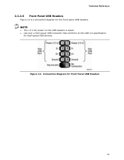
NOTE • The +5 V DC power on the USB headers is a connection diagram for high-speed USB devices. Technical Reference 2.2.2.6 Front Panel USB Headers Figure 12 is fused. • Use only a front panel USB connector that conforms to the USB 2.0 specification for the front panel USB headers. Connection Diagram for Front Panel USB Headers 53 Figure 12.
NOTE • The +5 V DC power on the USB headers is a connection diagram for high-speed USB devices. Technical Reference 2.2.2.6 Front Panel USB Headers Figure 12 is fused. • Use only a front panel USB connector that conforms to the USB 2.0 specification for the front panel USB headers. Connection Diagram for Front Panel USB Headers 53 Figure 12.

DB65AL Technical Product Specification
Page 63
... Maintenance Main Configuration Performance Security Power Boot Intel ME Exit NOTE The maintenance menu is displayed only when the board is accessed by pressing the key after the Power-On Self-Test (POST) memory test begins and before the operating system boot begins. The SPI Flash contains the BIOS Setup program, POST, LAN EEPROM information, Plug and Play support, and other firmware. The BIOS Setup program is in configure mode. The BIOS displays a message during POST identifying the type of utilities...
... Maintenance Main Configuration Performance Security Power Boot Intel ME Exit NOTE The maintenance menu is displayed only when the board is accessed by pressing the key after the Power-On Self-Test (POST) memory test begins and before the operating system boot begins. The SPI Flash contains the BIOS Setup program, POST, LAN EEPROM information, Plug and Play support, and other firmware. The BIOS Setup program is in configure mode. The BIOS displays a message during POST identifying the type of utilities...
DB65AL Technical Product Specification
Page 69
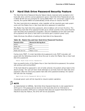
... another SATA port or computer that the User hard disk drive password is forgotten. The User hard disk drive password, when installed, will cause a hard disk to be accessible. 69 Only the installation of the User hard disk drive password will be required to resume system operation. Master Key and User Hard Drive Password Functions Password Set Password During Boot Neither None Master only None User only User only Master and User Set Master or User During every POST, if a User hard disk drive password is set in the event that does not support Hard Disk Drive Password...
... another SATA port or computer that the User hard disk drive password is forgotten. The User hard disk drive password, when installed, will cause a hard disk to be accessible. 69 Only the installation of the User hard disk drive password will be required to resume system operation. Master Key and User Hard Drive Password Functions Password Set Password During Boot Neither None Master only None User only User only Master and User Set Master or User During every POST, if a User hard disk drive password is set in the event that does not support Hard Disk Drive Password...

DB65AL Technical Product Specification
Page 74
... a device to reset values. The pattern repeats until the system is complete. BIOS Error Messages Error Message Explanation CMOS Battery Low The battery may have been corrupted. If no add-in graphics card 4.4 BIOS Error Messages Table 40 lists the error messages and provides a brief description of 16 blinks. Replace the battery soon. Run Setup to boot. 74 Intel Desktop Board DB65AL Technical Product Specification 4.3 Front-panel Power LED Blink Codes Whenever a recoverable error occurs during POST, the BIOS causes...
... a device to reset values. The pattern repeats until the system is complete. BIOS Error Messages Error Message Explanation CMOS Battery Low The battery may have been corrupted. If no add-in graphics card 4.4 BIOS Error Messages Table 40 lists the error messages and provides a brief description of 16 blinks. Replace the battery soon. Run Setup to boot. 74 Intel Desktop Board DB65AL Technical Product Specification 4.3 Front-panel Power LED Blink Codes Whenever a recoverable error occurs during POST, the BIOS causes...
DB65AL Technical Product Specification
Page 75
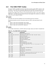
... POST sequence NOTE In the tables listed above, all POST codes and range values are listed in the Conventional PCI bus connector. Resuming from SX states. 0x10 -0x20 - Security (SEC) phase PEI phase pre MRC execution MRC memory detection PEI phase post MRC execution Recovery Platform DXE driver CPU Initialization (PEI, DXE, SMM) I /O port 80h. Error Messages and Beep Codes 4.5 Port 80h POST Codes During the POST, the BIOS generates diagnostic progress codes (POST codes...
... POST sequence NOTE In the tables listed above, all POST codes and range values are listed in the Conventional PCI bus connector. Resuming from SX states. 0x10 -0x20 - Security (SEC) phase PEI phase pre MRC execution MRC memory detection PEI phase post MRC execution Recovery Platform DXE driver CPU Initialization (PEI, DXE, SMM) I /O port 80h. Error Messages and Beep Codes 4.5 Port 80h POST Codes During the POST, the BIOS generates diagnostic progress codes (POST codes...
English Product Guide
Page 3
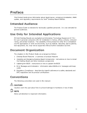
...Desktop Board Features: a summary of product features 2 Installing and Replacing Desktop Board Components: instructions on how to install the Desktop Board and other hardware components 3 Updating the BIOS: instructions on how to update the BIOS A Error Messages and Indicators: information about board layout, component installation, BIOS update, and regulatory requirements for Intel® Desktop Board DB65AL. NOTE Notes call attention to important information. Preface This Product Guide gives information about BIOS error messages and beep codes B Regulatory Compliance: describes the board...
...Desktop Board Features: a summary of product features 2 Installing and Replacing Desktop Board Components: instructions on how to install the Desktop Board and other hardware components 3 Updating the BIOS: instructions on how to update the BIOS A Error Messages and Indicators: information about board layout, component installation, BIOS update, and regulatory requirements for Intel® Desktop Board DB65AL. NOTE Notes call attention to important information. Preface This Product Guide gives information about BIOS error messages and beep codes B Regulatory Compliance: describes the board...
English Product Guide
Page 5
... USB Support ...18 SATA Support...18 SATA RAID 18 Intel® Rapid Recover Technology (Intel® RRT 19 Expandability...19 Legacy I/O ...19 BIOS ...20 SATA Auto Configuration 20 PCI*/PCI Express Auto Configuration 20 BIOS Security Passwords 20 Product Upgrade with a Purchased Permit 21 Intel Manageability Technology 21 Intel® MEBX Reset Header 21 Intel® Fast Call for Help 22 Fan Speed Control and Hardware Monitoring 23 Power Management 23 Software Support 23 Hardware Support 23 Onboard Speaker 26 Real-Time Clock Subsystem 26 2 Installing and Replacing Desktop Board...
... USB Support ...18 SATA Support...18 SATA RAID 18 Intel® Rapid Recover Technology (Intel® RRT 19 Expandability...19 Legacy I/O ...19 BIOS ...20 SATA Auto Configuration 20 PCI*/PCI Express Auto Configuration 20 BIOS Security Passwords 20 Product Upgrade with a Purchased Permit 21 Intel Manageability Technology 21 Intel® MEBX Reset Header 21 Intel® Fast Call for Help 22 Fan Speed Control and Hardware Monitoring 23 Power Management 23 Software Support 23 Hardware Support 23 Onboard Speaker 26 Real-Time Clock Subsystem 26 2 Installing and Replacing Desktop Board...
English Product Guide
Page 6
... Mono Speaker Header 45 Serial Header 46 Chassis Intrusion Header 46 Alternate Front Panel Power LED Header 46 Front Panel Header 47 Intel FCFH Header 47 Front Panel USB 2.0 Headers 48 S/PDIF Header 48 Connecting to the Audio System 49 Connecting Chassis Fan and Power Supply Cables 50 Connecting Chassis Fan Cables 50 Connecting Power Supply Cables 51 Setting the BIOS Configuration Jumper 52 Clearing Passwords in the BIOS Setup Program 53 Replacing the Battery 54 3 Updating the BIOS Updating the BIOS with the Intel® Express BIOS Update Utility 61 Updating the BIOS Using the...
... Mono Speaker Header 45 Serial Header 46 Chassis Intrusion Header 46 Alternate Front Panel Power LED Header 46 Front Panel Header 47 Intel FCFH Header 47 Front Panel USB 2.0 Headers 48 S/PDIF Header 48 Connecting to the Audio System 49 Connecting Chassis Fan and Power Supply Cables 50 Connecting Chassis Fan Cables 50 Connecting Power Supply Cables 51 Setting the BIOS Configuration Jumper 52 Clearing Passwords in the BIOS Setup Program 53 Replacing the Battery 54 3 Updating the BIOS Updating the BIOS with the Intel® Express BIOS Update Utility 61 Updating the BIOS Using the...
English Product Guide
Page 7
Location of the Chassis Fan Headers 50 24. Unlatch the Socket Lever 31 8. Install the Processor 33 11. Secure the Load Plate in Place 34 12. Connecting a Serial ATA Cable 43 21. Connecting Power Supply Cables 51 25. Intel Desktop Board DB65AL Components 12 2. LAN Status LEDs 17 3. Lift the Load Plate 32 9. Example Dual Channel Memory Configuration with Two DIMMs 36 14. Removing a PCI Express x16 Graphics Card 42 20. Back Panel Audio Connectors 49 23. Location of the Standby Power Indicator 25 5. Contents Japan VCCI...
Location of the Chassis Fan Headers 50 24. Unlatch the Socket Lever 31 8. Install the Processor 33 11. Secure the Load Plate in Place 34 12. Connecting a Serial ATA Cable 43 21. Connecting Power Supply Cables 51 25. Intel Desktop Board DB65AL Components 12 2. LAN Status LEDs 17 3. Lift the Load Plate 32 9. Example Dual Channel Memory Configuration with Two DIMMs 36 14. Removing a PCI Express x16 Graphics Card 42 20. Back Panel Audio Connectors 49 23. Location of the Standby Power Indicator 25 5. Contents Japan VCCI...
English Product Guide
Page 18
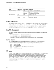
... back panel connectors and six ports routed to install separate RAID drivers using the F6 switch in the BIOS. See your Microsoft Windows XP documentation for more information about installing drivers during Microsoft Windows XP installation, you must press F6 to an eSATA adapter SATA RAID The Intel B65 PCH supports Intel® Rapid Storage Technology (Intel® RST) which enables the following RAID (Redundant Array of Independent Drives) levels: • RAID 0 - Intel Desktop Board DB65AL Product Guide Table 3. LAN Status LEDs States LED...
... back panel connectors and six ports routed to install separate RAID drivers using the F6 switch in the BIOS. See your Microsoft Windows XP documentation for more information about installing drivers during Microsoft Windows XP installation, you must press F6 to an eSATA adapter SATA RAID The Intel B65 PCH supports Intel® Rapid Storage Technology (Intel® RST) which enables the following RAID (Redundant Array of Independent Drives) levels: • RAID 0 - Intel Desktop Board DB65AL Product Guide Table 3. LAN Status LEDs States LED...
English Product Guide
Page 20
... password is booted. The BIOS can be accessed and who can be set , the computer boots without asking for booting the computer, with the following the instructions in card. BIOS Security Passwords The BIOS includes security features that add-in your computer. For instructions on resetting the password, go to view and change all Setup options. Intel Desktop Board DB65AL Product Guide BIOS The BIOS provides the Power-On Self-Test (POST), the BIOS Setup program, and the PCI/PCI Express and SATA auto-configuration utilities...
... password is booted. The BIOS can be accessed and who can be set , the computer boots without asking for booting the computer, with the following the instructions in card. BIOS Security Passwords The BIOS includes security features that add-in your computer. For instructions on resetting the password, go to view and change all Setup options. Intel Desktop Board DB65AL Product Guide BIOS The BIOS provides the Power-On Self-Test (POST), the BIOS Setup program, and the PCI/PCI Express and SATA auto-configuration utilities...
English Product Guide
Page 24
... connection. • All fan headers are compatible with 4-wire and 3-wire chassis fans. Fan Headers The function/operation of the computer through a network. Intel Desktop Board DB65AL Product Guide The Desktop Board has two power connectors. See Figure 24 on page 51 for the power supply must be capable of delivering adequate +5 V standby current. When signaled by a wake-up device or event, the computer quickly returns to a tachometer input. • All fan headers support closed-loop fan control that...
... connection. • All fan headers are compatible with 4-wire and 3-wire chassis fans. Fan Headers The function/operation of the computer through a network. Intel Desktop Board DB65AL Product Guide The Desktop Board has two power connectors. See Figure 24 on page 51 for the power supply must be capable of delivering adequate +5 V standby current. When signaled by a wake-up device or event, the computer quickly returns to a tachometer input. • All fan headers support closed-loop fan control that...
English Product Guide
Page 26
... power supply extends the life of the battery. Go to page 54 for instructions on a PCI Express bus add-in , the standby current from an ACPI S3, S4, or S5 state. PCI Express WAKE# Signal Wake-up Support When the PME# signal on the Desktop Board. When the battery voltage drops below a certain level, the BIOS Setup program settings stored in CMOS RAM (for a description of three years. Intel Desktop Board DB65AL Product Guide PCI PME# Signal Wake-up Support...
... power supply extends the life of the battery. Go to page 54 for instructions on a PCI Express bus add-in , the standby current from an ACPI S3, S4, or S5 state. PCI Express WAKE# Signal Wake-up Support When the PME# signal on the Desktop Board. When the battery voltage drops below a certain level, the BIOS Setup program settings stored in CMOS RAM (for a description of three years. Intel Desktop Board DB65AL Product Guide PCI PME# Signal Wake-up Support...
English Product Guide
Page 27
... modems before you how to: • Install the I/O shield • Install and remove the Desktop Board • Install and remove a processor • Install and remove memory • Install and remove a PCI Express x16 card • Connect Serial ATA cables • Connect to the internal headers • Connect to the audio system • Connect chassis fan and power supply cables • Set the BIOS configuration jumper • Clear passwords • Replace the battery Before You Begin CAUTIONS The procedures in this chapter assume familiarity with the general terminology associated...
... modems before you how to: • Install the I/O shield • Install and remove the Desktop Board • Install and remove a processor • Install and remove memory • Install and remove a PCI Express x16 card • Connect Serial ATA cables • Connect to the internal headers • Connect to the audio system • Connect chassis fan and power supply cables • Set the BIOS configuration jumper • Clear passwords • Replace the battery Before You Begin CAUTIONS The procedures in this chapter assume familiarity with the general terminology associated...
English Product Guide
Page 53
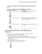
... devices connected to clear passwords. Table 14. Disconnect the computer's power cord from the AC power source (wall outlet or power adapter). 3. Place the jumper on page 27. 2. Jumper Settings for the BIOS Setup Program Modes Jumper Setting Mode Normal (default) (1-2) Description The BIOS uses the current configuration and passwords for the BIOS Setup program modes. Configure (2-3) After the Power-On Self-Test (POST) runs, the BIOS displays the Maintenance Menu. Clearing Passwords in the BIOS Setup Program This procedure assumes that the board is set...
... devices connected to clear passwords. Table 14. Disconnect the computer's power cord from the AC power source (wall outlet or power adapter). 3. Place the jumper on page 27. 2. Jumper Settings for the BIOS Setup Program Modes Jumper Setting Mode Normal (default) (1-2) Description The BIOS uses the current configuration and passwords for the BIOS Setup program modes. Configure (2-3) After the Power-On Self-Test (POST) runs, the BIOS displays the Maintenance Menu. Clearing Passwords in the BIOS Setup Program This procedure assumes that the board is set...


