
DB65AL Technical Product Specification
Page 7
... v 1 Product Description 1.1 Overview 11 1.1.1 Feature Summary 11 1.1.2 Board Layout 13 1.1.3 Block Diagram 15 1.2 Legacy Considerations 16 1.3 Online Support 16 1.4 Processor 16 1.5 Intel® B65 Express Chipset 17 1.6 System Memory 17 1.6.1 Memory Configurations 18 1.7 Graphics Subsystem 20 1.7.1 Integrated Graphics 20 1.7.2 PCI Express x16 Graphics 20 1.8 USB 21 1.9 SATA Interfaces 21 1.10 Legacy I/O Controller 22...
... v 1 Product Description 1.1 Overview 11 1.1.1 Feature Summary 11 1.1.2 Board Layout 13 1.1.3 Block Diagram 15 1.2 Legacy Considerations 16 1.3 Online Support 16 1.4 Processor 16 1.5 Intel® B65 Express Chipset 17 1.6 System Memory 17 1.6.1 Memory Configurations 18 1.7 Graphics Subsystem 20 1.7.1 Integrated Graphics 20 1.7.2 PCI Express x16 Graphics 20 1.8 USB 21 1.9 SATA Interfaces 21 1.10 Legacy I/O Controller 22...
DB65AL Technical Product Specification
Page 8
Intel Desktop Board DB65AL Technical Product Specification 1.16 Intel Standard Manageability Technology 30 1.16.1 Intel Standard Manageability Features 30 1.16.2 Intel® Active Management Technology Software and Drivers....... 32 1.17 Power Management 32 1.17.1 ACPI 33 1.17.2 Hardware Support 36 2 Technical Reference 2.1 Memory Resources 41 2.1.1 Addressable Memory 41 2.1.2 Memory Map 43 2.2 Connectors and Headers 43 2.2.1 Back Panel Connectors 44...
Intel Desktop Board DB65AL Technical Product Specification 1.16 Intel Standard Manageability Technology 30 1.16.1 Intel Standard Manageability Features 30 1.16.2 Intel® Active Management Technology Software and Drivers....... 32 1.17 Power Management 32 1.17.1 ACPI 33 1.17.2 Hardware Support 36 2 Technical Reference 2.1 Memory Resources 41 2.1.1 Addressable Memory 41 2.1.2 Memory Map 43 2.2 Connectors and Headers 43 2.2.1 Back Panel Connectors 44...
DB65AL Technical Product Specification
Page 9
...95H 285H 3. Back Panel Audio Connector Options 24 97H 287H 5. Connection Diagram for Front Panel USB Headers 53 105H 295H 13. System Memory Map 43 17H 307H 9. Contents 4 Error Messages and Beep Codes 4.1 Speaker 73 4.2 BIOS Beep Codes 73 4.3 Front-panel Power ...Panel Header 51 104H 294H 12. Intel MEBX Reset Header 56 107H 297H 15. Supported Memory Configurations 18 12H 302H 4. Component-side Connectors and Headers 45 103H 293H 11. Memory Channel and DIMM Configuration 19 96H 286H 4. Detailed System Memory Address Map 42 10H 291H 9. ...
...95H 285H 3. Back Panel Audio Connector Options 24 97H 287H 5. Connection Diagram for Front Panel USB Headers 53 105H 295H 13. System Memory Map 43 17H 307H 9. Contents 4 Error Messages and Beep Codes 4.1 Speaker 73 4.2 BIOS Beep Codes 73 4.3 Front-panel Power ...Panel Header 51 104H 294H 12. Intel MEBX Reset Header 56 107H 297H 15. Supported Memory Configurations 18 12H 302H 4. Component-side Connectors and Headers 45 103H 293H 11. Memory Channel and DIMM Configuration 19 96H 286H 4. Detailed System Memory Address Map 42 10H 291H 9. ...
DB65AL Technical Product Specification
Page 11
...Product Description 1.1 Overview 1.1.1 Feature Summary Table 1 summarizes the major features of system memory with four DIMMs using 4 Gb memory technology • Support for non-ECC memory • Integrated graphics support for processors with Intel® Graphics Technology: ― VGA ― DVI-D • Discrete graphics support...MHz and DDR3 1066 MHz DIMMs • Support for 1 Gb, 2 Gb, and 4 Gb memory technology • Support for PCI Express 2.0 x16 add-in graphics card • Intel® High Definition Audio: ― Realtek* ALC888S audio codec ― S/PDIF audio header &#...
...Product Description 1.1 Overview 1.1.1 Feature Summary Table 1 summarizes the major features of system memory with four DIMMs using 4 Gb memory technology • Support for non-ECC memory • Integrated graphics support for processors with Intel® Graphics Technology: ― VGA ― DVI-D • Discrete graphics support...MHz and DDR3 1066 MHz DIMMs • Support for 1 Gb, 2 Gb, and 4 Gb memory technology • Support for PCI Express 2.0 x16 add-in graphics card • Intel® High Definition Audio: ― Realtek* ALC888S audio codec ― S/PDIF audio header &#...
DB65AL Technical Product Specification
Page 16
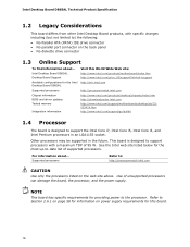
... about ... Intel Desktop Board DB65AL Desktop Board Support Available configurations for this World Wide Web site: http://www.intel.com/products/motherboard/index.htm http://www.intel.com/p/en_US/support?iid=hdr+support http://ark.intel.com Supported processors Chipset information BIOS and driver updates Tested memory Integration information http://processormatch.intel.com http://www.intel.com/products...
... about ... Intel Desktop Board DB65AL Desktop Board Support Available configurations for this World Wide Web site: http://www.intel.com/products/motherboard/index.htm http://www.intel.com/p/en_US/support?iid=hdr+support http://ark.intel.com Supported processors Chipset information BIOS and driver updates Tested memory Integration information http://processormatch.intel.com http://www.intel.com/products...
DB65AL Technical Product Specification
Page 17
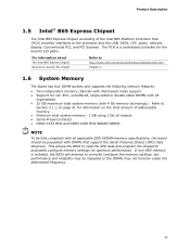
... Express chipset Resources used by the chipset Refer to Section 2.1.1 on the total amount of the Intel B65 Platform Controller Hub (PCH) provides interfaces to accurately configure memory settings for the board's I/O paths. This allows the BIOS to read the SPD data and ... USB, SATA, LPC, audio, network, display, Conventional PCI, and PCI Express. Product Description 1.5 Intel® B65 Express Chipset The Intel B65 Express Chipset consisting of addressable memory. • Minimum total system memory: 1 GB using 1 Gb x8 module • Serial Presence Detect • DDR3 1333 MHz and...
... Express chipset Resources used by the chipset Refer to Section 2.1.1 on the total amount of the Intel B65 Platform Controller Hub (PCH) provides interfaces to accurately configure memory settings for the board's I/O paths. This allows the BIOS to read the SPD data and ... USB, SATA, LPC, audio, network, display, Conventional PCI, and PCI Express. Product Description 1.5 Intel® B65 Express Chipset The Intel B65 Express Chipset consisting of addressable memory. • Minimum total system memory: 1 GB using 1 Gb x8 module • Serial Presence Detect • DDR3 1333 MHz and...
DB65AL Technical Product Specification
Page 18
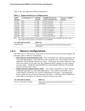
... This mode offers the highest throughput for each channel must be used when only a single DIMM is enabled when the installed memory capacities of memory organization: • Dual channel (Interleaved) mode. Intel Desktop Board DB65AL Technical Product Specification Table 3 lists the supported DIMM configurations. If different speed DIMMs are used between channels, the slowest...
... This mode offers the highest throughput for each channel must be used when only a single DIMM is enabled when the installed memory capacities of memory organization: • Dual channel (Interleaved) mode. Intel Desktop Board DB65AL Technical Product Specification Table 3 lists the supported DIMM configurations. If different speed DIMMs are used between channels, the slowest...

DB65AL Technical Product Specification
Page 19
Memory Channel and DIMM Configuration 19 Figure 3. Product Description Figure 3 illustrates the memory channel and DIMM configuration.
Memory Channel and DIMM Configuration 19 Figure 3. Product Description Figure 3 illustrates the memory channel and DIMM configuration.

DB65AL Technical Product Specification
Page 27
... supply extends the life of the battery. Product Description 1.13 Real-Time Clock Subsystem A coin-cell battery (CR2032) powers the real-time clock and CMOS memory. Replace the battery with power applied through the power supply 5V STBY rail. Figure 1 on page 13 shows the location of three years. When the...
... supply extends the life of the battery. Product Description 1.13 Real-Time Clock Subsystem A coin-cell battery (CR2032) powers the real-time clock and CMOS memory. Replace the battery with power applied through the power supply 5V STBY rail. Figure 1 on page 13 shows the location of three years. When the...
DB65AL Technical Product Specification
Page 41
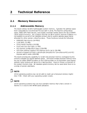
... be able to make use all of usable DRAM boundary to the 4 GB boundary to reclaim the physical memory overlapped by the memory mapped I /O that is shown in Section 2.1.1 due to system address space being allocated for Conventional PCI bus add-in cards ...functions. On a system that is no overlap of DRAM (total system memory). NOTE 32-bit operating systems may see less available memory than 4 GB. 2 Technical Reference 2.1 Memory Resources 2.1.1 Addressable Memory The board utilizes 32 GB of the system memory map. These functions include the following: • BIOS/SPI Flash device...
... be able to make use all of usable DRAM boundary to the 4 GB boundary to reclaim the physical memory overlapped by the memory mapped I /O that is shown in Section 2.1.1 due to system address space being allocated for Conventional PCI bus add-in cards ...functions. On a system that is no overlap of DRAM (total system memory). NOTE 32-bit operating systems may see less available memory than 4 GB. 2 Technical Reference 2.1 Memory Resources 2.1.1 Addressable Memory The board utilizes 32 GB of the system memory map. These functions include the following: • BIOS/SPI Flash device...
DB65AL Technical Product Specification
Page 43
...33550336 K Address Range 100000 - 7FFC00000 960 K - 1024 K F0000 - A fault in the load presented by Extended conventionfal mem) ory Conventional memory 2.2 Connectors and Headers CAUTION Only the following connectors and headers have overcurrent protection: back panel and front panel USB, and PS/2. Table 8. EFFFF...- 512 K 00000 - 7FFFF Size 32764 MB 64 KB 64 KB 96 KB 160 KB 1 KB 127 KB 512 KB Description Extended memory Runtime BIOS Reserved Potential available high DOS Video me(mory andhBIOS Extended BIOS data (movable by the external devices could cause damage to devices inside...
...33550336 K Address Range 100000 - 7FFC00000 960 K - 1024 K F0000 - A fault in the load presented by Extended conventionfal mem) ory Conventional memory 2.2 Connectors and Headers CAUTION Only the following connectors and headers have overcurrent protection: back panel and front panel USB, and PS/2. Table 8. EFFFF...- 512 K 00000 - 7FFFF Size 32764 MB 64 KB 64 KB 96 KB 160 KB 1 KB 127 KB 512 KB Description Extended memory Runtime BIOS Reserved Potential available high DOS Video me(mory andhBIOS Extended BIOS data (movable by the external devices could cause damage to devices inside...

DB65AL Technical Product Specification
Page 63
... of BIOS and a revision code. Maintenance Main Configuration Performance Security Power Boot Intel ME Exit NOTE The maintenance menu is displayed only when the board is stored in a 64 Mbit (8,192 KB) Serial Peripheral Interface Flash Memory (SPI Flash) device which can be updated using a set of utilities. ...Introduction The board uses an Intel BIOS that is in configure mode. Section 2.3 on page 54 shows how to view and change the BIOS settings for the computer. The menu bar is accessed by pressing the key after the Power-On Self-Test (POST) memory test begins and before ...
... of BIOS and a revision code. Maintenance Main Configuration Performance Security Power Boot Intel ME Exit NOTE The maintenance menu is displayed only when the board is stored in a 64 Mbit (8,192 KB) Serial Peripheral Interface Flash Memory (SPI Flash) device which can be updated using a set of utilities. ...Introduction The board uses an Intel BIOS that is in configure mode. Section 2.3 on page 54 shows how to view and change the BIOS settings for the computer. The menu bar is accessed by pressing the key after the Power-On Self-Test (POST) memory test begins and before ...
DB65AL Technical Product Specification
Page 64
...processor information Displays processor and memory configuration Configures advanced features available through the chipset Configures Memory and Processor overrides Sets passwords and security features Power Boot Configures power management features Selects boot options Intel ME Exit Configure Intel ME and Intel AMT settings Saves or discards... field (i.e., date/time) Executes command or selects the submenu Load the default configuration values for menu screens. Intel Desktop Board DB65AL Technical Product Specification Table 32 lists the BIOS Setup program menu features.
...processor information Displays processor and memory configuration Configures advanced features available through the chipset Configures Memory and Processor overrides Sets passwords and security features Power Boot Configures power management features Selects boot options Intel ME Exit Configure Intel ME and Intel AMT settings Saves or discards... field (i.e., date/time) Executes command or selects the submenu Load the default configuration values for menu screens. Intel Desktop Board DB65AL Technical Product Specification Table 32 lists the BIOS Setup program menu features.

DB65AL Technical Product Specification
Page 65
...; BIOS data, such as the BIOS revision level • Fixed-system data, such as peripherals, serial numbers, and asset tags • Resource data, such as memory size, cache size, and processor speed • Dynamic data, such as follows: 1. Legacy USB support operates as event detection and error logging Non-Plug and...
...; BIOS data, such as the BIOS revision level • Fixed-system data, such as peripherals, serial numbers, and asset tags • Resource data, such as memory size, cache size, and processor speed • Dynamic data, such as follows: 1. Legacy USB support operates as event detection and error logging Non-Plug and...
DB65AL Technical Product Specification
Page 66
Intel Desktop Board DB65AL Technical Product Specification 3.4 BIOS Updates The BIOS can be updated from a file on a hard disk, a USB drive (a flash drive or a USB drive), or an optical drive. • Intel® F7 switch allows a user to select where the BIOS .bio file is located ...help messages are available on a hard disk, a USB drive (a flash drive or a USB drive), or an optical drive. • Intel® Flash Memory Update Utility, which are supported in the Windows environment. NOTE Review the instructions distributed with the upgrade utility before attempting a BIOS update. ...
Intel Desktop Board DB65AL Technical Product Specification 3.4 BIOS Updates The BIOS can be updated from a file on a hard disk, a USB drive (a flash drive or a USB drive), or an optical drive. • Intel® F7 switch allows a user to select where the BIOS .bio file is located ...help messages are available on a hard disk, a USB drive (a flash drive or a USB drive), or an optical drive. • Intel® Flash Memory Update Utility, which are supported in the Windows environment. NOTE Review the instructions distributed with the upgrade utility before attempting a BIOS update. ...
DB65AL Technical Product Specification
Page 73
... keyboard input BIOS update in progress None Video error (no add-in graphics card 932 Hz High beep 2000 Hz Low beep 1500 Hz 73 Memory error On-off (1.0 second each) three times, then 2.5-second pause (off . Thermal trip warning Alternate high and low beeps (1.0 second each ) two times, then 2.5-second...
... keyboard input BIOS update in progress None Video error (no add-in graphics card 932 Hz High beep 2000 Hz Low beep 1500 Hz 73 Memory error On-off (1.0 second each) three times, then 2.5-second pause (off . Thermal trip warning Alternate high and low beeps (1.0 second each ) two times, then 2.5-second...

DB65AL Technical Product Specification
Page 74
...off ), entire pattern repeats (blink and pause) until the system is complete. Note For processors requiring an add-in graphics card installed) Memory error On-off (1.0 second each) two times, then 2.5-second pause (off (1.0 second each . The pattern repeats until the system is incorrect.... begins, then on , .25 seconds off . Table 40. Run Setup to boot. 74 Replace the battery soon. Table 39. Intel Desktop Board DB65AL Technical Product Specification 4.3 Front-panel Power LED Blink Codes Whenever a recoverable error occurs during POST, the BIOS causes the board's front ...
...off ), entire pattern repeats (blink and pause) until the system is complete. Note For processors requiring an add-in graphics card installed) Memory error On-off (1.0 second each) two times, then 2.5-second pause (off (1.0 second each . The pattern repeats until the system is incorrect.... begins, then on , .25 seconds off . Table 40. Run Setup to boot. 74 Replace the battery soon. Table 39. Intel Desktop Board DB65AL Technical Product Specification 4.3 Front-panel Power LED Blink Codes Whenever a recoverable error occurs during POST, the BIOS causes the board's front ...
DB65AL Technical Product Specification
Page 75
.... Not that critical since consoles should be installed in the Conventional PCI bus connector. S2, 0x30 - Security (SEC) phase PEI phase pre MRC execution MRC memory detection PEI phase post MRC execution Recovery Platform DXE driver CPU Initialization (PEI, DXE, SMM) I /O port 80h. Resuming from SX states. 0x10 -0x20 - If the...
.... Not that critical since consoles should be installed in the Conventional PCI bus connector. S2, 0x30 - Security (SEC) phase PEI phase pre MRC execution MRC memory detection PEI phase post MRC execution Recovery Platform DXE driver CPU Initialization (PEI, DXE, SMM) I /O port 80h. Resuming from SX states. 0x10 -0x20 - If the...
DB65AL Technical Product Specification
Page 76
Intel Desktop Board DB65AL Technical Product Specification Table 42. Port 80h POST Codes Port 80 Code Progress Code Enumeration ACPI S States 0x00,0x01,0x02,0x03,0x04,0x05 Entering S0, ... Programming 0x1B Entry to entry to PEI over-clock programming 0x1C Exit PEI over-clock programming Memory 0x21 0x23 MRC entry point Reading SPD from memory DIMMs 0x24 Detecting presence of memory DIMMs 0x27 Configuring memory 0x28 Testing memory 0x29 Exit MRC driver PEI after MRC 0x2A Start to Program MTRR Settings 0x2B Done Programming...
Intel Desktop Board DB65AL Technical Product Specification Table 42. Port 80h POST Codes Port 80 Code Progress Code Enumeration ACPI S States 0x00,0x01,0x02,0x03,0x04,0x05 Entering S0, ... Programming 0x1B Entry to entry to PEI over-clock programming 0x1C Exit PEI over-clock programming Memory 0x21 0x23 MRC entry point Reading SPD from memory DIMMs 0x24 Detecting presence of memory DIMMs 0x27 Configuring memory 0x28 Testing memory 0x29 Exit MRC driver PEI after MRC 0x2A Start to Program MTRR Settings 0x2B Done Programming...
DB65AL Technical Product Specification
Page 77
... Init smm relocate bases 0x45 Smm relocate bases for APs 0x46 End CPU SMM Init CPU DXE Phase 0x47 CPU DXE Phase begin 0x48 Refresh memory space attributes according to MTRRs 0x49 Load the microcode if needed 0x4A Initialize strings to HII database 0x4B Initialize MP support 0x4C CPU DXE Phase...
... Init smm relocate bases 0x45 Smm relocate bases for APs 0x46 End CPU SMM Init CPU DXE Phase 0x47 CPU DXE Phase begin 0x48 Refresh memory space attributes according to MTRRs 0x49 Load the microcode if needed 0x4A Initialize strings to HII database 0x4B Initialize MP support 0x4C CPU DXE Phase...


