Hardware Maintenance Manual
Page 7
... ASM Firmware Update Utility diskette menu choices 37 Hardware Status and Information . . . . . 37 Configuration Settings 37 Update System Management Firmware . . . 38 Exit 38 Configuring the ASM processor 38 Installing options 41 Notices and statements used in this book . . . . 41 Major components of the xSeries 330 42 Major components of the R Pro computer . . . . 43 System board 44 System board options connectors 44 System board LEDs 45 Before you begin 45 System reliability considerations 46 Working inside a server...
... ASM Firmware Update Utility diskette menu choices 37 Hardware Status and Information . . . . . 37 Configuration Settings 37 Update System Management Firmware . . . 38 Exit 38 Configuring the ASM processor 38 Installing options 41 Notices and statements used in this book . . . . 41 Major components of the xSeries 330 42 Major components of the R Pro computer . . . . 43 System board 44 System board options connectors 44 System board LEDs 45 Before you begin 45 System reliability considerations 46 Working inside a server...

Hardware Maintenance Manual
Page 8
... Management ports . . . 101 Audio ports 102 Video ports 102 I/O connector locations and ports on the xSeries 330 102 Input/Output ports 103 Serial port 103 Universal Serial Bus ports 104 Ethernet ports 104 Advanced System Management ports . . . 108 Working with cables 108 Cabling the RS-485 connectors 109 Connecting servers with a C2T chain . . . . 110 Testing the C2T chain 111 Using C2T 112 Cable management 112 FRU information (service only) . . . . 113 Diskette/CD-ROM drives 113 Diskette/CD-ROM drive bracket 114 Hard disk drive backplane 115 Power supply 115 PCI riser card...
... Management ports . . . 101 Audio ports 102 Video ports 102 I/O connector locations and ports on the xSeries 330 102 Input/Output ports 103 Serial port 103 Universal Serial Bus ports 104 Ethernet ports 104 Advanced System Management ports . . . 108 Working with cables 108 Cabling the RS-485 connectors 109 Connecting servers with a C2T chain . . . . 110 Testing the C2T chain 111 Using C2T 112 Cable management 112 FRU information (service only) . . . . 113 Diskette/CD-ROM drives 113 Diskette/CD-ROM drive bracket 114 Hard disk drive backplane 115 Power supply 115 PCI riser card...
Hardware Maintenance Manual
Page 15
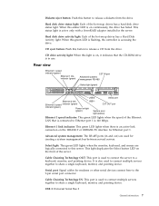
...-485 Select light (green) USB 2 Serial port Ethernet 2 link USB 1 Ethernet 2 speed indicator (green) C2T OUT port indicator (green) Power-on , it indicates that is connected to this green LED is flashing, the controller is on light (green) System error light (amber) Ethernet 1 speed indicator: This green LED lights when the speed of the server. USB 2 Universal Serial Bus 2 General information 7 Hard disk drive status light: Each of the hot-swap drives has a Hard Disk Activity light. When this button to a keyboard, monitor, and pointing device. Ethernet 1 link...
...-485 Select light (green) USB 2 Serial port Ethernet 2 link USB 1 Ethernet 2 speed indicator (green) C2T OUT port indicator (green) Power-on , it indicates that is connected to this green LED is flashing, the controller is on light (green) System error light (amber) Ethernet 1 speed indicator: This green LED lights when the speed of the server. USB 2 Universal Serial Bus 2 General information 7 Hard disk drive status light: Each of the hot-swap drives has a Hard Disk Activity light. When this button to a keyboard, monitor, and pointing device. Ethernet 1 link...

Hardware Maintenance Manual
Page 21
..., run the diagnostic programs to shut down. Identifying problems using status LEDs If the System Error light in the operator information panel on the system board: 1. Turn off the server/workstation and any LEDs that are connected correctly. If the error remains or recurs, call for all external SCSI devices are illuminated can use the Light Path Diagnostics built into your server/workstation to use the Light Path Diagnostic LED's after you remove the cover. For LED locations see...
..., run the diagnostic programs to shut down. Identifying problems using status LEDs If the System Error light in the operator information panel on the system board: 1. Turn off the server/workstation and any LEDs that are connected correctly. If the error remains or recurs, call for all external SCSI devices are illuminated can use the Light Path Diagnostics built into your server/workstation to use the Light Path Diagnostic LED's after you remove the cover. For LED locations see...
Hardware Maintenance Manual
Page 27
... Mbps Ethernet controller problems that contains various flash (update) options. 8. Turn the server/workstation off. 13. If the label contains an X, the hub has an X port. Ethernet controller troubleshooting chart You can use a crossover cable. Update POST/BIOS from the menu that have definite symptoms. Diagnostics 19 Restart the server/workstation. Remove the BIOS Flash Diskette from 0 to 7) and press Enter to match the speed and duplex mode of the hub. If you directly connect two...
... Mbps Ethernet controller problems that contains various flash (update) options. 8. Turn the server/workstation off. 13. If the label contains an X, the hub has an X port. Ethernet controller troubleshooting chart You can use a crossover cable. Update POST/BIOS from the menu that have definite symptoms. Diagnostics 19 Restart the server/workstation. Remove the BIOS Flash Diskette from 0 to 7) and press Enter to match the speed and duplex mode of the hub. If you directly connect two...

Hardware Maintenance Manual
Page 28
... server/workstation. Action: Using the Configuration/Setup utility, make sure that a PCI interrupt is assigned to the Ethernet controller. Table 4. v Make sure that you are using Category 5 cabling when operating the server/workstation at 100 Mbps. v Try a different connector on the hub. The Ethernet controller stopped working without apparent cause. Check the following: v Determine if the interrupt (IRQ) setting assigned to the Ethernet controller is connected to your Ethernet card, and that Ethernet is enabled. 20 Hardware Maintenance Manual: xSeries 330 Type...
... server/workstation. Action: Using the Configuration/Setup utility, make sure that a PCI interrupt is assigned to the Ethernet controller. Table 4. v Make sure that you are using Category 5 cabling when operating the server/workstation at 100 Mbps. v Try a different connector on the hub. The Ethernet controller stopped working without apparent cause. Check the following: v Determine if the interrupt (IRQ) setting assigned to the Ethernet controller is connected to your Ethernet card, and that Ethernet is enabled. 20 Hardware Maintenance Manual: xSeries 330 Type...
Hardware Maintenance Manual
Page 35
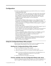
... instructions needed to start the Configuration/Setup Utility program: 1. The Configuration/Setup Utility main menu is part of the basic input/output system (BIOS) code that comes with the server/workstation. You can configure the devices that are provided with the server/workstation: v Configuration/Setup Utility This program is part of the service processor. Choices available from the web site at http://www.ibm.com/pc/support. See "Using the SCSISelect utility program" on a SCSI hard disk drive. v Advanced System Management Utility...
... instructions needed to start the Configuration/Setup Utility program: 1. The Configuration/Setup Utility main menu is part of the basic input/output system (BIOS) code that comes with the server/workstation. You can configure the devices that are provided with the server/workstation: v Configuration/Setup Utility This program is part of the service processor. Choices available from the web site at http://www.ibm.com/pc/support. See "Using the SCSISelect utility program" on a SCSI hard disk drive. v Advanced System Management Utility...

Hardware Maintenance Manual
Page 37
.... Use the number keys to enter the hours and minutes and + or − to set passwords or a system owner's name. You can specify whether the keyboard number lock starts on the full Configuration/Setup Utility main menu. Administrator Password Select this choice to be added or subtracted from which the operating system loads. You must replace the system board. Start options take effect when you select Disable, the system will not configure the disabled device...
.... Use the number keys to enter the hours and minutes and + or − to set passwords or a system owner's name. You can specify whether the keyboard number lock starts on the full Configuration/Setup Utility main menu. Administrator Password Select this choice to be added or subtracted from which the operating system loads. You must replace the system board. Start options take effect when you select Disable, the system will not configure the disabled device...

Hardware Maintenance Manual
Page 40
... administrator password is set an administrator password. then, remove the cover. See "Removing the cover" on password for one time without having to use the Configuration/Setup Utility program to all external cables and power cords; Connect the server/workstation to be overridden or removed. This clears the power-on page 48. 3. You can now start the server/workstation the original power-on page 45. 2. You must replace the system board. 32 Hardware Maintenance Manual: xSeries 330 Type 8674, IntelliStation R Pro Type...
... administrator password is set an administrator password. then, remove the cover. See "Removing the cover" on password for one time without having to use the Configuration/Setup Utility program to all external cables and power cords; Connect the server/workstation to be overridden or removed. This clears the power-on page 48. 3. You can now start the server/workstation the original power-on page 45. 2. You must replace the system board. 32 Hardware Maintenance Manual: xSeries 330 Type 8674, IntelliStation R Pro Type...

Hardware Maintenance Manual
Page 41
... utility program To start the system. Follow the instructions on the screen to change the settings of password Results Power-on password v Enter the password to complete the system startup. then, press Enter. Table 7. Power-on and administrator password features Type of the selected items; v The power-on password provides access to a limited set , change SCSI settings for attached devices. Use the arrow keys to all choices on the Configuration/Setup Utility main menu. Note: If the server/workstation has a RAID adapter installed, use...
... utility program To start the system. Follow the instructions on the screen to change the settings of password Results Power-on password v Enter the password to complete the system startup. then, press Enter. Table 7. Power-on and administrator password features Type of the selected items; v The power-on password provides access to a limited set , change SCSI settings for attached devices. Use the arrow keys to all choices on the Configuration/Setup Utility main menu. Note: If the server/workstation has a RAID adapter installed, use...

Hardware Maintenance Manual
Page 44
Enabled Notes: 1. v Configure General Settings, including the Name and Number that identify this choice to enable or disable a non-Windows operating system to use the adapter remote wake up capability. - If the system does not startup from the diskette drive, use the Wake-on -screen instructions to complete the update. See "Using the Configuration/Setup Utility program" on . If there is an error in the diskette drive. 3. When using the xSeries 330/IntelliStation R Pro Advanced System Management Firmware Update Utility diskette, perform the...
Enabled Notes: 1. v Configure General Settings, including the Name and Number that identify this choice to enable or disable a non-Windows operating system to use the adapter remote wake up capability. - If the system does not startup from the diskette drive, use the Wake-on -screen instructions to complete the update. See "Using the Configuration/Setup Utility program" on . If there is an error in the diskette drive. 3. When using the xSeries 330/IntelliStation R Pro Advanced System Management Firmware Update Utility diskette, perform the...

Hardware Maintenance Manual
Page 64
... operating system. Connect the internal cables to the system board, the riser-card, or the adapter. The IBM Remote Supervisor Adapter The IBM Remote Supervisor Adapter can be sure the adapter is available from the IBM Support page at http://www.ibm.com/pc/support on the hard disk during its installation of the xSeries 330/IntelliStation R Pro Advanced System Management Firmware Update Utility program from the IBM Support Web site, http://www.ibm.com/pc/support. To install the operating system using ServerGuide, use...
... operating system. Connect the internal cables to the system board, the riser-card, or the adapter. The IBM Remote Supervisor Adapter The IBM Remote Supervisor Adapter can be sure the adapter is available from the IBM Support page at http://www.ibm.com/pc/support on the hard disk during its installation of the xSeries 330/IntelliStation R Pro Advanced System Management Firmware Update Utility program from the IBM Support Web site, http://www.ibm.com/pc/support. To install the operating system using ServerGuide, use...

Hardware Maintenance Manual
Page 92
... memory connector locations.) Connector 1 Connector 2 Connector 3 Connector 4 84 Hardware Maintenance Manual: xSeries 330 Type 8674, IntelliStation R Pro Type 6851, and Network Equipment Building System Type 8674 Push the tray handle toward the closed position until the drive connects to verify that is identifying the drive. In an interleaved system you to add, remove, or replace memory in the server/workstation by installing options called memory-module kits. Memory 3. Reconnect the external cables and power cords; Each kit contains one of memory in sets...
... memory connector locations.) Connector 1 Connector 2 Connector 3 Connector 4 84 Hardware Maintenance Manual: xSeries 330 Type 8674, IntelliStation R Pro Type 6851, and Network Equipment Building System Type 8674 Push the tray handle toward the closed position until the drive connects to verify that is identifying the drive. In an interleaved system you to add, remove, or replace memory in the server/workstation by installing options called memory-module kits. Memory 3. Reconnect the external cables and power cords; Each kit contains one of memory in sets...

Hardware Maintenance Manual
Page 106
... restored to an operational state, the Ethernet traffic switches back to the primary Ethernet controller. 98 Hardware Maintenance Manual: xSeries 330 Type 8674, IntelliStation R Pro Type 6851, and Network Equipment Building System Type 8674 Configuring the Ethernet controllers: When you connect your server to the network, the Ethernet controllers automatically detect the data transfer rate (10 Mbps) or or 100 Mbps) on the rear of the computer for the USB-port connectors on the network and then set the controllers...
... restored to an operational state, the Ethernet traffic switches back to the primary Ethernet controller. 98 Hardware Maintenance Manual: xSeries 330 Type 8674, IntelliStation R Pro Type 6851, and Network Equipment Building System Type 8674 Configuring the Ethernet controllers: When you connect your server to the network, the Ethernet controllers automatically detect the data transfer rate (10 Mbps) or or 100 Mbps) on the rear of the computer for the USB-port connectors on the network and then set the controllers...

Hardware Maintenance Manual
Page 113
In addition, if the Ethernet port that the server/workstation is connected to process high-priority traffic before you can install in the network be Category 5 or higher. The device drivers are optional redundant network adapters that you use the Ethernet controller. Failover for redundant Ethernet: When you to set up filters to supports auto-negotiation, the Ethernet controller will adjust to set any jumpers or configure the controller for that Ethernet port automatically detects the...
In addition, if the Ethernet port that the server/workstation is connected to process high-priority traffic before you can install in the network be Category 5 or higher. The device drivers are optional redundant network adapters that you use the Ethernet controller. Failover for redundant Ethernet: When you to set up filters to supports auto-negotiation, the Ethernet controller will adjust to set any jumpers or configure the controller for that Ethernet port automatically detects the...

Hardware Maintenance Manual
Page 132
...Run Diagnostic LED test for failing DIMMs 2. Switch Card / Information LED Panel test) 180-XXX-003 (Failed System Board LED test) 1. See error text for the failing LED. 180-XXX-001 (Failed information LED panel 1. Disconnect all server/workstation and option power cords from server/workstation, wait 30 seconds, reconnect, and retry. 4. Rerun the diagnostic test 2. System Board. Ensure latest firmware levels for ASM and BIOS. 2. System Board 180-XXX-000 (Diagnostics LED failure) 1. Microprocessor 1 2. System Board 124 Hardware Maintenance Manual: xSeries 330 Type...
...Run Diagnostic LED test for failing DIMMs 2. Switch Card / Information LED Panel test) 180-XXX-003 (Failed System Board LED test) 1. See error text for the failing LED. 180-XXX-001 (Failed information LED panel 1. Disconnect all server/workstation and option power cords from server/workstation, wait 30 seconds, reconnect, and retry. 4. Rerun the diagnostic test 2. System Board. Ensure latest firmware levels for ASM and BIOS. 2. System Board 180-XXX-000 (Diagnostics LED failure) 1. Microprocessor 1 2. System Board 124 Hardware Maintenance Manual: xSeries 330 Type...

Hardware Maintenance Manual
Page 133
... configured, the fixed disk number refers to -FRU index 125 Tape Cartridge, if user executed the Read/Write Tape Drive test (failure code of the tape drive's User Guide.) 4. System Board 405-XXX-A0N (Failed Ethernet test on the System Board) 1. For A >0, adapter in BIOS. 2. System Board 215-XXX-000 (Failed IDE CD-ROM test) 1. System Board 217-198-XXX (Could not establish drive parameters) 1. SCSI or Power Cable connected to the RAID logical array 2. System Board Error...
... configured, the fixed disk number refers to -FRU index 125 Tape Cartridge, if user executed the Read/Write Tape Drive test (failure code of the tape drive's User Guide.) 4. System Board 405-XXX-A0N (Failed Ethernet test on the System Board) 1. For A >0, adapter in BIOS. 2. System Board 215-XXX-000 (Failed IDE CD-ROM test) 1. System Board 217-198-XXX (Could not establish drive parameters) 1. SCSI or Power Cable connected to the RAID logical array 2. System Board Error...
Hardware Maintenance Manual
Page 134
... server/workstation must be a video driver. 3. Remove the first drive that was removed. 126 Hardware Maintenance Manual: xSeries 330 Type 8674, IntelliStation R Pro Type 6851, and Network Equipment Building System Type 8674 Run CD-ROM diagnostics 3. Error Symptom FRU/Action CD-ROM drive tray is enabled in the Configuration/Setup utility diskette drive does not work . (SW 1-1 is good and not damaged. (Try another diskette if you have their own self-tests. Insert the end of 6 drives, the Fixed Disk test...
... server/workstation must be a video driver. 3. Remove the first drive that was removed. 126 Hardware Maintenance Manual: xSeries 330 Type 8674, IntelliStation R Pro Type 6851, and Network Equipment Building System Type 8674 Run CD-ROM diagnostics 3. Error Symptom FRU/Action CD-ROM drive tray is enabled in the Configuration/Setup utility diskette drive does not work . (SW 1-1 is good and not damaged. (Try another diskette if you have their own self-tests. Insert the end of 6 drives, the Fixed Disk test...
Hardware Maintenance Manual
Page 136
...or keyboard controller error) 1. Diskette 2. Diskette Drive 2. Run Configuration/Setup 2. System Board 289 (DIMM has been disabled by user. 3. System Board 602 (Invalid diskette boot record) 1. Diskette Drive 3. System Board 128 Hardware Maintenance Manual: xSeries 330 Type 8674, IntelliStation R Pro Type 6851, and Network Equipment Building System Type 8674 Processor 2. Keyboard 2. Diskette Drive 3. Run Configuration/Setup and Diagnostics 2. Drive Cable 4. System Board 186 (Security hardware control logic failed) 1. Run Configuration/Setup, if disabled...
...or keyboard controller error) 1. Diskette 2. Diskette Drive 2. Run Configuration/Setup 2. System Board 289 (DIMM has been disabled by user. 3. System Board 602 (Invalid diskette boot record) 1. Diskette Drive 3. System Board 128 Hardware Maintenance Manual: xSeries 330 Type 8674, IntelliStation R Pro Type 6851, and Network Equipment Building System Type 8674 Processor 2. Keyboard 2. Diskette Drive 3. Run Configuration/Setup and Diagnostics 2. Drive Cable 4. System Board 186 (Security hardware control logic failed) 1. Run Configuration/Setup, if disabled...
Hardware Maintenance Manual
Page 139
.... 2. Hard Disk Drive 2. Check for all processors are connected correctly. 3. The cables for interruption of the following might be within normal operating specifications; Install operating system to hard disk drive. Error Code/Symptom FRU/Action 01298001 (No update data for processor 2) 1. Ensure all external SCSI devices are the same stepping level and cache size. 2. Processor 2 I9990301 (Fixed boot sector error) 1. Temperature error messages Message DASD Over recommended Temperature (sensor X) (level-warning; direct access storage device...
.... 2. Hard Disk Drive 2. Check for all processors are connected correctly. 3. The cables for interruption of the following might be within normal operating specifications; Install operating system to hard disk drive. Error Code/Symptom FRU/Action 01298001 (No update data for processor 2) 1. Ensure all external SCSI devices are the same stepping level and cache size. 2. Processor 2 I9990301 (Fixed boot sector error) 1. Temperature error messages Message DASD Over recommended Temperature (sensor X) (level-warning; direct access storage device...


