
User Guide
Page 10
Statement 5: ≥ 55 kg (121.2 lb) CAUTION: The power control button on the device and the power switch on the power supply do not turn off the electrical current supplied to the device. The device also might have more than one power cord. To remove all electrical current from the device, ensure that all power cords are disconnected from the power source. 2 1 viii IBM xSeries 205Type 8480:User's Guide Statement 4: ≥ 18 kg (39.7 lb) ≥ 32 kg (70.5 lb) CAUTION: Use safe practices when lifting.
Statement 5: ≥ 55 kg (121.2 lb) CAUTION: The power control button on the device and the power switch on the power supply do not turn off the electrical current supplied to the device. The device also might have more than one power cord. To remove all electrical current from the device, ensure that all power cords are disconnected from the power source. 2 1 viii IBM xSeries 205Type 8480:User's Guide Statement 4: ≥ 18 kg (39.7 lb) ≥ 32 kg (70.5 lb) CAUTION: Use safe practices when lifting.

User Guide
Page 11
Statement 8: CAUTION: Never remove the cover on a power supply or any component that has the following label attached. Hazardous voltage, current, and energy levels are no serviceable parts inside any part that has this label attached. Safety information ix If you suspect a problem with one of these components. There are present inside these parts, contact a service technician.
Statement 8: CAUTION: Never remove the cover on a power supply or any component that has the following label attached. Hazardous voltage, current, and energy levels are no serviceable parts inside any part that has this label attached. Safety information ix If you suspect a problem with one of these components. There are present inside these parts, contact a service technician.

User Guide
Page 15
... installed and the powermanagement optional features in . These levels were measured in . Introducing the xSeries 205 Type 8480 server 3 Some features and specifications are reported in .) • Weight: approximately 19.5 kg...channel bus mastering IDE controller • Support for IBM Remote Supervisor Adapter Acoustical noise emissions: • Sound power, idling: 5.1 bel maximum • Sound power, operating: 5.3 bel maximum PCI expansion slots:... ac - Maximum: 265 V ac • Input kilovolt-amperes (kVA) approximately: - Power supply: One 340 watt (90240 V ac) Chapter 1.
... installed and the powermanagement optional features in . These levels were measured in . Introducing the xSeries 205 Type 8480 server 3 Some features and specifications are reported in .) • Weight: approximately 19.5 kg...channel bus mastering IDE controller • Support for IBM Remote Supervisor Adapter Acoustical noise emissions: • Sound power, idling: 5.1 bel maximum • Sound power, operating: 5.3 bel maximum PCI expansion slots:... ac - Maximum: 265 V ac • Input kilovolt-amperes (kVA) approximately: - Power supply: One 340 watt (90240 V ac) Chapter 1.

User Guide
Page 17
... the integrity of the data that you can use to centrally manage xSeries servers. Reliability, availability, and serviceability features Three important server design features are reliability, availability, and serviceability (RAS). • IBM Director IBM Director is a workgroup-hardware-management tool that is stored in self-...) data bus • Predictive failure analysis® (PFA) on memory, microprocessor, hard disk drives, fans, and power supply • Auto-restart initial program load (IPL) power supply • Wake on your server. Introducing the xSeries 205 Type 8480 server 5
... the integrity of the data that you can use to centrally manage xSeries servers. Reliability, availability, and serviceability features Three important server design features are reliability, availability, and serviceability (RAS). • IBM Director IBM Director is a workgroup-hardware-management tool that is stored in self-...) data bus • Predictive failure analysis® (PFA) on memory, microprocessor, hard disk drives, fans, and power supply • Auto-restart initial program load (IPL) power supply • Wake on your server. Introducing the xSeries 205 Type 8480 server 5

User Guide
Page 20
...on LAN feature turned on the server, the Wake on the power supply do not turn off in any of the following ways: • You can turn off the server. • You can remove all power cords are disconnected from the power source. 2 1 The server can be turned on in ... require an orderly shutdown before you can press the power-control button to start the operating system by disconnecting the server from the ac power source. 8 IBM xSeries 205Type 8480:User's Guide The device also might have more than one power cord. Server power features When you connect the server to prevent the ...
...on LAN feature turned on the server, the Wake on the power supply do not turn off in any of the following ways: • You can turn off the server. • You can remove all power cords are disconnected from the power source. 2 1 The server can be turned on in ... require an orderly shutdown before you can press the power-control button to start the operating system by disconnecting the server from the ac power source. 8 IBM xSeries 205Type 8480:User's Guide The device also might have more than one power cord. Server power features When you connect the server to prevent the ...

Hardware Maintenance Manual
Page 8
... backplane 70 Microprocessor / fan sink 71 Hot-swap hard disk drive cage 72 Power supply 73 Rear fan 74 Extender card 75 System board 77 CD-ROM drive 78 ... or single SCSI channel using one hot-swap drive SCSI backplane 46 Installing internal drives 48 Internal drive bays 48 Preinstallation steps 49 Power and signal cables for internal drives 50 Installing a drive in bay 1, 2, 3, or 4 51 Installing a non-hot-swap...Optional system-management adapter ports 65 Chapter 5. Symptom-to-FRU index 85 vi IBM xSeries 205 Type 8480: Hardware Maintenance Manual and Troubleshooting Guide
... backplane 70 Microprocessor / fan sink 71 Hot-swap hard disk drive cage 72 Power supply 73 Rear fan 74 Extender card 75 System board 77 CD-ROM drive 78 ... or single SCSI channel using one hot-swap drive SCSI backplane 46 Installing internal drives 48 Internal drive bays 48 Preinstallation steps 49 Power and signal cables for internal drives 50 Installing a drive in bay 1, 2, 3, or 4 51 Installing a non-hot-swap...Optional system-management adapter ports 65 Chapter 5. Symptom-to-FRU index 85 vi IBM xSeries 205 Type 8480: Hardware Maintenance Manual and Troubleshooting Guide

Hardware Maintenance Manual
Page 9
...service and support 118 Appendix B. Parts listing Type 8480 111 System 112 Keyboard CRUs 113 Power cords 114 Appendix A. Beep symptoms 86 No-beep symptoms 87 Diagnostic panel system error LED 88 Diagnostic error codes 90 Error symptoms 95 Power-supply LED errors 96 POST error codes 97 POST ...(ISPR) error procedures 100 ServeRAID error codes 102 Service processor error codes 103 SCSI error codes 103 Temperature error messages 104 Fan error messages 104 Power error messages 105 System shutdown ...
...service and support 118 Appendix B. Parts listing Type 8480 111 System 112 Keyboard CRUs 113 Power cords 114 Appendix A. Beep symptoms 86 No-beep symptoms 87 Diagnostic panel system error LED 88 Diagnostic error codes 90 Error symptoms 95 Power-supply LED errors 96 POST error codes 97 POST ...(ISPR) error procedures 100 ServeRAID error codes 102 Service processor error codes 103 SCSI error codes 103 Temperature error messages 104 Fan error messages 104 Power error messages 105 System shutdown ...

Hardware Maintenance Manual
Page 13
... National Standards Institute (ANSI) S12.10 and ISO 7779 and are reported in - Minimum: 90 V ac - Power supply: One 330 watt (90-240 V ac) power supply or one CD-ROM drive installed) v Two 3.5-in British thermal units (Btu) per hour v Minimum configuration: ...according to 2133 m (6998.0.7 ft) - The declared sound-power levels indicate an upper limit, below which a large number of the features and specifications for IBM Remote Supervisor Adapter Acoustical noise emissions: v Sound power, idling: 5.1 bel maximum v Sound power, operating: 5.3 bel maximum Environment: v Air temperature: -...
... National Standards Institute (ANSI) S12.10 and ISO 7779 and are reported in - Minimum: 90 V ac - Power supply: One 330 watt (90-240 V ac) power supply or one CD-ROM drive installed) v Two 3.5-in British thermal units (Btu) per hour v Minimum configuration: ...according to 2133 m (6998.0.7 ft) - The declared sound-power levels indicate an upper limit, below which a large number of the features and specifications for IBM Remote Supervisor Adapter Acoustical noise emissions: v Sound power, idling: 5.1 bel maximum v Sound power, operating: 5.3 bel maximum Environment: v Air temperature: -...

Hardware Maintenance Manual
Page 16
...and start the operating system by pressing the power-control button. To remove all electrical current from the device, ensure that all power cords are disconnected from being turned off in any of the following ways: 6 IBM xSeries 205 Type 8480: Hardware Maintenance Manual and Troubleshooting Guide Turning ... can turn on , the server will restart automatically when power is connected to the device. The following ways: v You can be turned on the power supply do not turn off the electrical current supplied to an ac power source, it can be turned on the server. See ...
...and start the operating system by pressing the power-control button. To remove all electrical current from the device, ensure that all power cords are disconnected from being turned off in any of the following ways: 6 IBM xSeries 205 Type 8480: Hardware Maintenance Manual and Troubleshooting Guide Turning ... can turn on , the server will restart automatically when power is connected to the device. The following ways: v You can be turned on the power supply do not turn off the electrical current supplied to an ac power source, it can be turned on the server. See ...

Hardware Maintenance Manual
Page 31
... run the diagnostic programs to "Undetermined problems" on page 119. 7. v One or more information. If the computer stops with your server. For power supply problems, see "Safety information" on page 108. 5. If you cannot determine whether a problem is identified as part of a shared DASD cluster. ...For intermittent problems, check the error log. © Copyright IBM Corp. 2002 21 If you can run all tests in looped mode. Do not run one test at least one or more systems are...
... run the diagnostic programs to "Undetermined problems" on page 119. 7. v One or more information. If the computer stops with your server. For power supply problems, see "Safety information" on page 108. 5. If you cannot determine whether a problem is identified as part of a shared DASD cluster. ...For intermittent problems, check the error log. © Copyright IBM Corp. 2002 21 If you can run all tests in looped mode. Do not run one test at least one or more systems are...

Hardware Maintenance Manual
Page 46
P Serial port (COM) ASM Interconnect port (RJ-14) Error LED (amber) P- P Power LED (green) External power supply connector (not used) 36 IBM xSeries 205 Type 8480: Hardware Maintenance Manual and Troubleshooting Guide System board external connectors The following illustration shows the connectors and LEDs for external cables. Ethernet link status LED (...
P Serial port (COM) ASM Interconnect port (RJ-14) Error LED (amber) P- P Power LED (green) External power supply connector (not used) 36 IBM xSeries 205 Type 8480: Hardware Maintenance Manual and Troubleshooting Guide System board external connectors The following illustration shows the connectors and LEDs for external cables. Ethernet link status LED (...

Hardware Maintenance Manual
Page 60
... used on a cable, it attaches to internal drives: v The drives that the drive connector at the other as a primary device. 50 IBM xSeries 205 Type 8480: Hardware Maintenance Manual and Troubleshooting Guide If the cable has a gray middle connector, it must be designated as a primary device. v If ...Ultra160 twisted ribbon cable connects the internal Ultra160 SCSI hard disk drive to the power supply. v When you have only one IDE device on a single cable, one end of ribbon cables come with power and signal cables attached. Note: The CD-ROM drive is determined by switch ...
... used on a cable, it attaches to internal drives: v The drives that the drive connector at the other as a primary device. 50 IBM xSeries 205 Type 8480: Hardware Maintenance Manual and Troubleshooting Guide If the cable has a gray middle connector, it must be designated as a primary device. v If ...Ultra160 twisted ribbon cable connects the internal Ultra160 SCSI hard disk drive to the power supply. v When you have only one IDE device on a single cable, one end of ribbon cables come with power and signal cables attached. Note: The CD-ROM drive is determined by switch ...

Hardware Maintenance Manual
Page 75
Optional system-management adapter ports The following illustration shows the connectors and LEDs for detailed information about the advanced system management (ASM) interconnect network. P Power light (green) External power supply connector (not used) Chapter 4. See the Remote Supervisor Adapter option documentation for the Remote Supervisor Adapter (optional system-management adapter). P Serial port (COM) ASM Interconnect port (RJ-14) Error light (amber) P- Ethernet link status light (green) Ethernet activity light (green) Ethernet port (RJ-45) P- Installing options 65
Optional system-management adapter ports The following illustration shows the connectors and LEDs for detailed information about the advanced system management (ASM) interconnect network. P Power light (green) External power supply connector (not used) Chapter 4. See the Remote Supervisor Adapter option documentation for the Remote Supervisor Adapter (optional system-management adapter). P Serial port (COM) ASM Interconnect port (RJ-14) Error light (amber) P- Ethernet link status light (green) Ethernet activity light (green) Ethernet port (RJ-45) P- Installing options 65

Hardware Maintenance Manual
Page 77
... (CRU) or a FRU. Note: Before servicing this section. Field replaceable units Removing the front bezel 68 Power button 69 Hot-swap backplane 70 Microprocessor / fan sink 71 Hot-swap hard disk drive cage 72 Power supply 73 Rear fan 74 Extender card 75 System board 77 CD-ROM drive 78 Diskette drive 79... guidelines" on page 112 to determine if the component being replaced is authorized to access the components described in "System" on page 37.. © Copyright IBM Corp. 2002 67 Important: The field replaceable unit (FRU) procedures are familiar with...
... (CRU) or a FRU. Note: Before servicing this section. Field replaceable units Removing the front bezel 68 Power button 69 Hot-swap backplane 70 Microprocessor / fan sink 71 Hot-swap hard disk drive cage 72 Power supply 73 Rear fan 74 Extender card 75 System board 77 CD-ROM drive 78 Diskette drive 79... guidelines" on page 112 to determine if the component being replaced is authorized to access the components described in "System" on page 37.. © Copyright IBM Corp. 2002 67 Important: The field replaceable unit (FRU) procedures are familiar with...

Hardware Maintenance Manual
Page 83
Field replaceable units 73 Remove the screws from the planar and drives. 5. Gently move the power supply away from the chassis and lift it is on page 40. 4. Turn off the server, if it out of the server. 6. Disconnect internal cables from the rear of the server. Chapter 5. Unplug the server. 3. Remove the cover. v Read "System reliability considerations" on page 119. Power supply Note: v Read "Safety information" on page 33. To remove the power supply, do the following: 1. See "Removing the side cover" on . 2.
Field replaceable units 73 Remove the screws from the planar and drives. 5. Gently move the power supply away from the chassis and lift it is on page 40. 4. Turn off the server, if it out of the server. 6. Disconnect internal cables from the rear of the server. Chapter 5. Unplug the server. 3. Remove the cover. v Read "System reliability considerations" on page 119. Power supply Note: v Read "Safety information" on page 33. To remove the power supply, do the following: 1. See "Removing the side cover" on . 2.

Hardware Maintenance Manual
Page 95
...index Beep symptoms 86 No-beep symptoms 87 Diagnostic panel system error LED 88 Diagnostic error codes 90 Error symptoms 95 Power-supply LED errors 96 POST error codes 97 POST (ISPR) error procedures 100 ServeRAID error codes 102 Service processor error ... fault messages 107 Undetermined problems 108 Problem determination tips 109 This index supports xSeries 205 servers. Check the configuration before replacing the component. Always start with "General checkout" on the screen. © Copyright IBM Corp. 2002 85 Note: Try reseating a suspected component or reconnecting a cable...
...index Beep symptoms 86 No-beep symptoms 87 Diagnostic panel system error LED 88 Diagnostic error codes 90 Error symptoms 95 Power-supply LED errors 96 POST error codes 97 POST (ISPR) error procedures 100 ServeRAID error codes 102 Service processor error ... fault messages 107 Undetermined problems 108 Problem determination tips 109 This index supports xSeries 205 servers. Check the configuration before replacing the component. Always start with "General checkout" on the screen. © Copyright IBM Corp. 2002 85 Note: Try reseating a suspected component or reconnecting a cable...

Hardware Maintenance Manual
Page 99
... panel is also on . 1. If it is off , replace power supply 1. 2. a. If the CPU LED on power supply 2. FAN LED on . 1. Symptom-to determine which components should be within normal operating specifications. POWER SUPPLY 1 LED on 1. NONREDUNDANT LED on ) 1) Overheating hard drive ...board. 5. Note: See "System" on . 1. See "Features and specifications" on . 1. Check the PS1 and PS2 LEDs and replace any indicated power supply. 2. NMI LED on page 3. 2. Restart the server. 2. System over recommended temperature for CPU x (where x is 1 or 2) (CPU LED...
... panel is also on . 1. If it is off , replace power supply 1. 2. a. If the CPU LED on power supply 2. FAN LED on . 1. Symptom-to determine which components should be within normal operating specifications. POWER SUPPLY 1 LED on 1. NONREDUNDANT LED on ) 1) Overheating hard drive ...board. 5. Note: See "System" on . 1. See "Features and specifications" on . 1. Check the PS1 and PS2 LEDs and replace any indicated power supply. 2. NMI LED on page 3. 2. Restart the server. 2. System over recommended temperature for CPU x (where x is 1 or 2) (CPU LED...

Hardware Maintenance Manual
Page 101
Adapter. 2. SCSI backplane. 4. It may be replaced by a field service technician. Disconnect all server and option power cords from the server, wait 30 seconds, reconnect, and retry. 4. System board. 166-201-001 System Management: Failed 1. Reseat memory ... test again. 2. s = number of failing PCI slot, nn = SCSI ID of failing PCI slot. Cable. 3. Adapter. 075-XXX-000 (Failed power supply test.) v Power supply 089-XXX-001 (Failed microprocessor test.) 1. Run the test again.) 1. If installed, reseat the I2C cable between the Remote (I2C bus error(s) See SERVPROC...
Adapter. 2. SCSI backplane. 4. It may be replaced by a field service technician. Disconnect all server and option power cords from the server, wait 30 seconds, reconnect, and retry. 4. System board. 166-201-001 System Management: Failed 1. Reseat memory ... test again. 2. s = number of failing PCI slot, nn = SCSI ID of failing PCI slot. Cable. 3. Adapter. 075-XXX-000 (Failed power supply test.) v Power supply 089-XXX-001 (Failed microprocessor test.) 1. Run the test again.) 1. If installed, reseat the I2C cable between the Remote (I2C bus error(s) See SERVPROC...
Hardware Maintenance Manual
Page 102
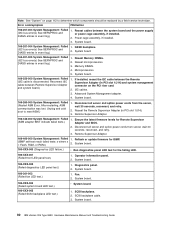
.... Remote Supervisor Adapter. 166-342-000 System Management: Failed 1. Operator information panel. 2. Fan. 2. System board. 92 IBM xSeries 205 Type 8480: Hardware Maintenance Manual and Troubleshooting Guide Power cage assembly, if installed. 3. Reseat Memory DIMMs. (I2C bus error(s) See SERVPROC and DIAGS entries in event log.) .... 180-XXX-001 (Failed front LED panel test.) 1. Reseat cables between the system board and the power supply (I2C bus error(s) See SERVPROC and or power cage assembly, if installed. After restarting, ASM wait 30 seconds, reconnect, and retry. Note: See ...
.... Remote Supervisor Adapter. 166-342-000 System Management: Failed 1. Operator information panel. 2. Fan. 2. System board. 92 IBM xSeries 205 Type 8480: Hardware Maintenance Manual and Troubleshooting Guide Power cage assembly, if installed. 3. Reseat Memory DIMMs. (I2C bus error(s) See SERVPROC and DIAGS entries in event log.) .... 180-XXX-001 (Failed front LED panel test.) 1. Reseat cables between the system board and the power supply (I2C bus error(s) See SERVPROC and or power cage assembly, if installed. After restarting, ASM wait 30 seconds, reconnect, and retry. Note: See ...

Hardware Maintenance Manual
Page 106
... 1. see "System and PCI extender boards" on the system. Power supply. Remove the adapters and disconnect the cables and power connectors to bypass the power switch; Turn on page 34. Power supply. 4. N/A 96 IBM xSeries 205 Type 8480: Hardware Maintenance Manual and Troubleshooting Guide CD-ROM drive problems Symptom FRU..." on page 112 to determine which components should be replaced by a field service technician. On On Power is : v Power supply v Power cage assembly, if installed. Tape drive test failed. AC good LED DC good LED Description FRU/action Off Off No...
... 1. see "System and PCI extender boards" on the system. Power supply. Remove the adapters and disconnect the cables and power connectors to bypass the power switch; Turn on page 34. Power supply. 4. N/A 96 IBM xSeries 205 Type 8480: Hardware Maintenance Manual and Troubleshooting Guide CD-ROM drive problems Symptom FRU..." on page 112 to determine which components should be replaced by a field service technician. On On Power is : v Power supply v Power cage assembly, if installed. Tape drive test failed. AC good LED DC good LED Description FRU/action Off Off No...

