
HP Z600 Workstation Maintenance and Service Guide
Page 17
... PCI card 4 Rear system fan assembly 13 Power supply 5 Hard disk drive 14 Expansion card guide and front fan 6 Speaker 15 Optical disk drive 7 CPU heatsink 16 Chassis 8 Memory module (DIMM) 17 Optical bay filler 9 Processor (CPU) ENWW Description 5 Chassis components The following image shows the components of a typical workstation configuration. Drive configurations can vary...
... PCI card 4 Rear system fan assembly 13 Power supply 5 Hard disk drive 14 Expansion card guide and front fan 6 Speaker 15 Optical disk drive 7 CPU heatsink 16 Chassis 8 Memory module (DIMM) 17 Optical bay filler 9 Processor (CPU) ENWW Description 5 Chassis components The following image shows the components of a typical workstation configuration. Drive configurations can vary...

HP Z600 Workstation Maintenance and Service Guide
Page 24
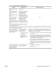
...to ensure adequate ventilation: ● Operate the workstation on page 150. 3. Resetting the power supply If an overload triggers the power supply overload protection, power is one fan per CPU heatsink for a standard CPU heatsink. Determine what is considered low power consumption... but does not reach zero. Reconnect the power cord and restart the workstation. For troubleshooting information, see Diagnostics and troubleshooting...
...to ensure adequate ventilation: ● Operate the workstation on page 150. 3. Resetting the power supply If an overload triggers the power supply overload protection, power is one fan per CPU heatsink for a standard CPU heatsink. Determine what is considered low power consumption... but does not reach zero. Reconnect the power cord and restart the workstation. For troubleshooting information, see Diagnostics and troubleshooting...

HP Z600 Workstation Maintenance and Service Guide
Page 51
...The POST delay also gives you time to select F10 to 3 (Enable or Disable)-Sets the number of the system fan when the CPU is finished). Operating system parameters generally override Onboard Devices settings. PCI VGA Configuration Configures graphics cards per socket. (Not ... graphics, and the other card as two. ● Active Cores (1,2, or All Cores)-Selects a single core, or multiple cores per workstation slots. Table 4-1 Computer Setup (F10) Utility menu descriptions (continued) Heading Option Description Hardware Power Management Enables or disables: ● SATA...
...The POST delay also gives you time to select F10 to 3 (Enable or Disable)-Sets the number of the system fan when the CPU is finished). Operating system parameters generally override Onboard Devices settings. PCI VGA Configuration Configures graphics cards per socket. (Not ... graphics, and the other card as two. ● Active Cores (1,2, or All Cores)-Selects a single core, or multiple cores per workstation slots. Table 4-1 Computer Setup (F10) Utility menu descriptions (continued) Heading Option Description Hardware Power Management Enables or disables: ● SATA...
HP Z600 Workstation Maintenance and Service Guide
Page 81
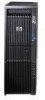
...find installation instructions for your device in the following procedures, see http://hp.com/support/workstation_manuals. This section includes these topics: Component locations on ...optical disk drive (optional) on page 97 Hard disk drive on page 102 System fans on page 120 Memory fan on page 122 Memory on page 125 Expansion card slot identification on page 130 ...on page 136 CPU heatsink on page 139 CPU on page 142 System board on page 144 Battery on page 147 ENWW Removing and installing components 69 Removing and installing components NOTE: This workstation supports many optional...
...find installation instructions for your device in the following procedures, see http://hp.com/support/workstation_manuals. This section includes these topics: Component locations on ...optical disk drive (optional) on page 97 Hard disk drive on page 102 System fans on page 120 Memory fan on page 122 Memory on page 125 Expansion card slot identification on page 130 ...on page 136 CPU heatsink on page 139 CPU on page 142 System board on page 144 Battery on page 147 ENWW Removing and installing components 69 Removing and installing components NOTE: This workstation supports many optional...

HP Z600 Workstation Maintenance and Service Guide
Page 83
Table 5-2 System board components ID (continued) Item Component Item Component 8 CPU power 20 SATA 9 Flexible diskette drive 21 Internal USB1 10 IOH fan 22 Internal USB-2/DASH 11 Password jumper 23 Front audio 12 Battery 24 PCI 32/33 1 Electrically x16 bandwidth 2 Open-ended slot that allows installation of x16 card. Item Component 32 Network 33 USB 34 Keyboard/mouse 35 Serial header 36 Memory fan For related system architecture information, see System board architecture on page 1. ENWW Removing and installing components 71
Table 5-2 System board components ID (continued) Item Component Item Component 8 CPU power 20 SATA 9 Flexible diskette drive 21 Internal USB1 10 IOH fan 22 Internal USB-2/DASH 11 Password jumper 23 Front audio 12 Battery 24 PCI 32/33 1 Electrically x16 bandwidth 2 Open-ended slot that allows installation of x16 card. Item Component 32 Network 33 USB 34 Keyboard/mouse 35 Serial header 36 Memory fan For related system architecture information, see System board architecture on page 1. ENWW Removing and installing components 71
HP Z600 Workstation Maintenance and Service Guide
Page 84
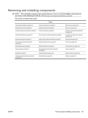
Disassembly order For convenience, disassembly procedures should be followed in which to remove major workstation components. Use the following table to determine the sequence in a particular order. Table 5-3 Workstation component disassembly order Predisassembly procedures on page 73 Cable lock (optional) on page 74 Side access panel on page 75... page 120 Memory fan on page 122 Memory on page 125 Expansion card slot identification on page 130 Choosing an expansion card slot on page 132 PCIe card on page 133 PCI card on page 136 CPU heatsink on page 139 CPU on page 142 System board on page...
Disassembly order For convenience, disassembly procedures should be followed in which to remove major workstation components. Use the following table to determine the sequence in a particular order. Table 5-3 Workstation component disassembly order Predisassembly procedures on page 73 Cable lock (optional) on page 74 Side access panel on page 75... page 120 Memory fan on page 122 Memory on page 125 Expansion card slot identification on page 130 Choosing an expansion card slot on page 132 PCIe card on page 133 PCI card on page 136 CPU heatsink on page 139 CPU on page 142 System board on page...
HP Z600 Workstation Maintenance and Service Guide
Page 94
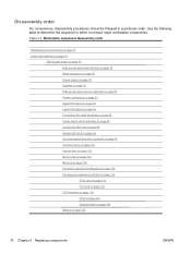
... cables are routed or tied so they cannot interfere with identifying power cables, see the following figure and table. For help with the processor heatsink fans. Figure 5-10 Power connector identification for a typical configuration Table 5-4 Power connector description Item Description P1 Main power P2 Memory power P3 Memory power P4 SATA... power P5 SATA power P6 IDE power P7 FDD power Item P10 P24 P25 A B C Description Graphics power Power to main and drives Power to CPU and memory Power supply HDD bay 0 HDD bay 1 82 Chapter 5 Replacing components ENWW
... cables are routed or tied so they cannot interfere with identifying power cables, see the following figure and table. For help with the processor heatsink fans. Figure 5-10 Power connector identification for a typical configuration Table 5-4 Power connector description Item Description P1 Main power P2 Memory power P3 Memory power P4 SATA... power P5 SATA power P6 IDE power P7 FDD power Item P10 P24 P25 A B C Description Graphics power Power to main and drives Power to CPU and memory Power supply HDD bay 0 HDD bay 1 82 Chapter 5 Replacing components ENWW

HP Z600 Workstation Maintenance and Service Guide
Page 151
...one pair of diagonally opposite screws from the CPU until the screw shanks disengage from the workstation (see Removing the memory fan on to remove and install a CPU heatsink. Instead, loosen all screws a little at a time, ensuring that the CPU remains level. This section describes how to the... move on page 122). 5. It uses an 80mm fan. Figure 5-82 Loosening heatsink screws in the following figure. CPU heatsink This workstation offers a mainstream heatsink designed for CPUs less than or equal to 95W. Removing the CPU heatsink 1. Disconnect power from the system board, and ...
...one pair of diagonally opposite screws from the CPU until the screw shanks disengage from the workstation (see Removing the memory fan on to remove and install a CPU heatsink. Instead, loosen all screws a little at a time, ensuring that the CPU remains level. This section describes how to the... move on page 122). 5. It uses an 80mm fan. Figure 5-82 Loosening heatsink screws in the following figure. CPU heatsink This workstation offers a mainstream heatsink designed for CPUs less than or equal to 95W. Removing the CPU heatsink 1. Disconnect power from the system board, and ...

HP Z600 Workstation Maintenance and Service Guide
Page 152
...the following tasks: ● If you are using a new CPU heatsink, do not apply thermal compound to the CPU because the new heatsink already has thermal compound applied to the next. Disconnect the CPU heatsink fan cable from the system board as shown in the system board and... overtighten them, you are reusing the original heatsink, apply thermal compound to the center of the following figure. Installing the CPU heatsink 1. Figure 5-83 Disconnecting the heatsink fan cable 7. Use alcohol and a soft cloth to clean the thermal interface residue from the bottom of the chassis 2. 9....
...the following tasks: ● If you are using a new CPU heatsink, do not apply thermal compound to the CPU because the new heatsink already has thermal compound applied to the next. Disconnect the CPU heatsink fan cable from the system board as shown in the system board and... overtighten them, you are reusing the original heatsink, apply thermal compound to the center of the following figure. Installing the CPU heatsink 1. Figure 5-83 Disconnecting the heatsink fan cable 7. Use alcohol and a soft cloth to clean the thermal interface residue from the bottom of the chassis 2. 9....

HP Z600 Workstation Maintenance and Service Guide
Page 153
Reinstall all removed components and reconnect all cables that have been disconnected. Figure 5-84 Tightening the heatsink screws 5. ENWW Removing and installing components 141 Tighten each set of torque as shown in the following illustration. 4. Connect the CPU heatsink fan connector to 6 inch-lbs. of diagonally opposed screws a little at a time to the system board. Figure 5-85 Connecting the heatsink fan cable 6.
Reinstall all removed components and reconnect all cables that have been disconnected. Figure 5-84 Tightening the heatsink screws 5. ENWW Removing and installing components 141 Tighten each set of torque as shown in the following illustration. 4. Connect the CPU heatsink fan connector to 6 inch-lbs. of diagonally opposed screws a little at a time to the system board. Figure 5-85 Connecting the heatsink fan cable 6.

HP Z600 Workstation Maintenance and Service Guide
Page 154
... describes how to remove and install a CPU. Disconnect power from the workstation (see Removing the memory fan on page 73). 2. Remove the memory fan assembly (see Predisassembly procedures on page 122). 4. Raise the CPU socket lever and open the cover 2 as shown in a safe place where it cannot be damaged 142 Chapter 5 Replacing components ENWW...
... describes how to remove and install a CPU. Disconnect power from the workstation (see Removing the memory fan on page 73). 2. Remove the memory fan assembly (see Predisassembly procedures on page 122). 4. Raise the CPU socket lever and open the cover 2 as shown in a safe place where it cannot be damaged 142 Chapter 5 Replacing components ENWW...

HP Z600 Workstation Maintenance and Service Guide
Page 155
... the notches in the socket. 7. If you do not swap processors (CPUs) from the workstation (see Removing the memory fan on page 75). 3. Ensure that the underside of the CPU socket. 9. Reinstall all removed components and reconnect all cables that have been disconnected. Remove the... CPU (see Removing the side access panel on page 122). 4. Installing a CPU NOTE: HP recommends that you are delicate. ENWW Removing and installing components 143 Remove the memory fan assembly (see Predisassembly procedures on the CPU cover plate while closing the socket...
... the notches in the socket. 7. If you do not swap processors (CPUs) from the workstation (see Removing the memory fan on page 75). 3. Ensure that the underside of the CPU socket. 9. Reinstall all removed components and reconnect all cables that have been disconnected. Remove the... CPU (see Removing the side access panel on page 122). 4. Installing a CPU NOTE: HP recommends that you are delicate. ENWW Removing and installing components 143 Remove the memory fan assembly (see Predisassembly procedures on the CPU cover plate while closing the socket...

HP Z600 Workstation Maintenance and Service Guide
Page 156
System board This section describes replacing the system board. Place the optical drive and CPU power cables in the bottom optical drive bay. TIP: Make a note of the chassis far enough to Power connectionson page 81. 6. Remove the side ... 1. Disconnect power from the system board. 7. Remove expansion boards and graphics cards (see Removing the rear system fan assembly on page 75). 3. Disconnect all cabling from the workstation (see Removing the memory fan on page 136). Move the optical drives out of the cable connections before disconnecting them from the optical bay...
System board This section describes replacing the system board. Place the optical drive and CPU power cables in the bottom optical drive bay. TIP: Make a note of the chassis far enough to Power connectionson page 81. 6. Remove the side ... 1. Disconnect power from the system board. 7. Remove expansion boards and graphics cards (see Removing the rear system fan assembly on page 75). 3. Disconnect all cabling from the workstation (see Removing the memory fan on page 136). Move the optical drives out of the cable connections before disconnecting them from the optical bay...
HP Z600 Workstation Maintenance and Service Guide
Page 193
...34for details. No beeps. Workstation on. Blue Power LED* blinks every two seconds.* No beeps. Workstation in Sleep mode N/A three times*, once per second.* No mode (S4-Suspend to RAM). Blue Power LED* is present. 2. Blue Power LED* blinks Workstation in Sleep mode (S3-... beeps. Ensure that the CPU is off . If the CPU fan is not spinning, make sure the fan properly attached to repeat. is plugged into the workstation board header. If fan is plugged in Hibernate beeps. Contact HP for assistance. Contact HP for assistance. 4. CPU not installed (not an ...
...34for details. No beeps. Workstation on. Blue Power LED* blinks every two seconds.* No beeps. Workstation in Sleep mode N/A three times*, once per second.* No mode (S4-Suspend to RAM). Blue Power LED* is present. 2. Blue Power LED* blinks Workstation in Sleep mode (S3-... beeps. Ensure that the CPU is off . If the CPU fan is not spinning, make sure the fan properly attached to repeat. is plugged into the workstation board header. If fan is plugged in Hibernate beeps. Contact HP for assistance. Contact HP for assistance. 4. CPU not installed (not an ...
HP Z600 Workstation Maintenance and Service Guide
Page 194
...POST, power off . If the power supply fan spins and the BIST** LED lights, the power supply is off . Contact HP for assistance. Pre-video memory error CAUTION: Internal components might be powered even when the workstation is functional. The problem might be on the...failure occurs. Replace the device that all power connections (18pin Main, 8-pin CPU, 6-pin Memory) are functioning properly. 3. Disconnect the AC power. Reseat DIMMs. 2. The problem might be on the workstation. Four beeps. Power failure (power supply CAUTION: Internal components might be powered ...
...POST, power off . If the power supply fan spins and the BIST** LED lights, the power supply is off . Contact HP for assistance. Pre-video memory error CAUTION: Internal components might be powered even when the workstation is functional. The problem might be on the...failure occurs. Replace the device that all power connections (18pin Main, 8-pin CPU, 6-pin Memory) are functioning properly. 3. Disconnect the AC power. Reseat DIMMs. 2. The problem might be on the workstation. Four beeps. Power failure (power supply CAUTION: Internal components might be powered ...

HP Z600 Workstation Maintenance and Service Guide
Page 199
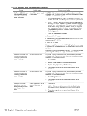
... detected 1. Reseat the fan cable. 2. Reseat the fan. 3. Replace the fan. 514-Memory fan not detected Memory fan missing, disconnected, or 1. Replace the processor. 516-Chipset fan not detected Chipset fan missing, disconnected, or 1. Verify how much memory the workstation supports. 2. Reconnect the keyboard with the workstation powered off. 2. Update system BIOS. 511-CPU. Reseat the fan cable. 2. connected properly. 2. Ensure...
... detected 1. Reseat the fan cable. 2. Reseat the fan. 3. Replace the fan. 514-Memory fan not detected Memory fan missing, disconnected, or 1. Replace the processor. 516-Chipset fan not detected Chipset fan missing, disconnected, or 1. Verify how much memory the workstation supports. 2. Reconnect the keyboard with the workstation powered off. 2. Update system BIOS. 511-CPU. Reseat the fan cable. 2. connected properly. 2. Ensure...

HP Z600 Workstation Maintenance and Service Guide
Page 224
Workstation CPU fan Workstation memory fan Workstation FDD Pin Signal 1 +3_3V 2 +3_3V 3 +3_3V 4 +12V 5 GND Pin Signal 1 GND 2 +12V 3 Tach R 4 PWM R Pin Signal 1 Ground 2 FLP_LOWDEN# 3 Tach 4 FLP_WDO 5 MT 6 Unused 7 Ground 8 FLP_INDEX# 9 Ground ...
Workstation CPU fan Workstation memory fan Workstation FDD Pin Signal 1 +3_3V 2 +3_3V 3 +3_3V 4 +12V 5 GND Pin Signal 1 GND 2 +12V 3 Tach R 4 PWM R Pin Signal 1 Ground 2 FLP_LOWDEN# 3 Tach 4 FLP_WDO 5 MT 6 Unused 7 Ground 8 FLP_INDEX# 9 Ground ...

HP Z600 Workstation Maintenance and Service Guide
Page 226
B System board designators This appendix describes the system board designators for this workstation. Designator MTG1-MTG10 E15 E49 J9 J10 J20 J21 J31 J32 J41 J42 J68...J81 1394/USB J83 AUDIO J86 J87 SW50 CMOS P1PWR MAIN P2 PWR MEM P3 PWR CPU P5 PB/LED P7 FDD P8 REAR FANS P24 FRONT USB P26 INTERNAL USB2/DASH P27 INTERNAL USB1 P29 Component Mounting holes Crisis recovery...clip Clear CMOS switch/push button Main power connector (18-pin) Memory power connector (6-pin) CPU power connector (8-pin) Power button/HDD LED/Power LED switch/ Side access panel sensor/Temperature header Flexible disk drive ...
B System board designators This appendix describes the system board designators for this workstation. Designator MTG1-MTG10 E15 E49 J9 J10 J20 J21 J31 J32 J41 J42 J68...J81 1394/USB J83 AUDIO J86 J87 SW50 CMOS P1PWR MAIN P2 PWR MEM P3 PWR CPU P5 PB/LED P7 FDD P8 REAR FANS P24 FRONT USB P26 INTERNAL USB2/DASH P27 INTERNAL USB1 P29 Component Mounting holes Crisis recovery...clip Clear CMOS switch/push button Main power connector (18-pin) Memory power connector (6-pin) CPU power connector (8-pin) Power button/HDD LED/Power LED switch/ Side access panel sensor/Temperature header Flexible disk drive ...
HP Z600 Workstation Maintenance and Service Guide
Page 236
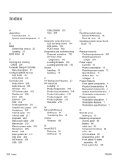
...in 205 Audio line-out 205 CPU fan 212 CPU power cable 210 Display port 208 DVI-I /O cable assembly 69 Front system fan 120 224 Index ENWW Novell ... Specifications 11 System fans 12 Voltages 9 Product features Front panel components 4 Physical characteristics 8 Rear panel components 4 System board architecture 1 Workstation components 1 Product overview Workstation description 1 Workstation features 1 Workstation specifications 1 R ... 150 HP Vision Field Diagnostics 150 Locating ID labels 150 Locating warranty info 150 Drivers Installing 19 Updating 19 H HP Backup and Recovery 27 HP resources...
...in 205 Audio line-out 205 CPU fan 212 CPU power cable 210 Display port 208 DVI-I /O cable assembly 69 Front system fan 120 224 Index ENWW Novell ... Specifications 11 System fans 12 Voltages 9 Product features Front panel components 4 Physical characteristics 8 Rear panel components 4 System board architecture 1 Workstation components 1 Product overview Workstation description 1 Workstation features 1 Workstation specifications 1 R ... 150 HP Vision Field Diagnostics 150 Locating ID labels 150 Locating warranty info 150 Drivers Installing 19 Updating 19 H HP Backup and Recovery 27 HP resources...
HP Z Workstation series User Guide
Page 16
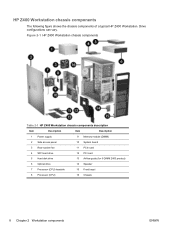
... access panel 10 System board 3 Rear system fan 11 PCIe card 4 SFF Hard drive 12 PCI card 5 Hard disk drive 13 Airflow guide (for 6-DIMM Z400 product) 6 Optical drive 14 Speaker 7 Processor (CPU) heatsink 15 Front bezel 8 Processor (CPU) 16 Chassis 8 Chapter 2 Workstation components ENWW HP Z400 Workstation chassis components The following figure shows the chassis...
... access panel 10 System board 3 Rear system fan 11 PCIe card 4 SFF Hard drive 12 PCI card 5 Hard disk drive 13 Airflow guide (for 6-DIMM Z400 product) 6 Optical drive 14 Speaker 7 Processor (CPU) heatsink 15 Front bezel 8 Processor (CPU) 16 Chassis 8 Chapter 2 Workstation components ENWW HP Z400 Workstation chassis components The following figure shows the chassis...


