Service Manual
Page 6
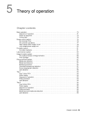
... sequence 73 Timing chart 74 Engine control system 75 DC controller PCA 76 DC controller operations 77 High-voltage power supply circuit 78 Low-voltage power supply unit 80 Formatter system 81 Formatter hardware 81 Laser/scanner system 83 Image formation system 84 The eight processes of image formation 84 Print ...-level detection 87 Multifeed prevention 87 Overhead-transparency detection 87 Fuser-wrapping-jam detection 87 Jam detection 88 Tray 1 93 Tray 1 driver PCA 93 Power supply 93 Sequence of operation 93 Pickup and feed 94 Jam detection 94 iv Table of contents
... sequence 73 Timing chart 74 Engine control system 75 DC controller PCA 76 DC controller operations 77 High-voltage power supply circuit 78 Low-voltage power supply unit 80 Formatter system 81 Formatter hardware 81 Laser/scanner system 83 Image formation system 84 The eight processes of image formation 84 Print ...-level detection 87 Multifeed prevention 87 Overhead-transparency detection 87 Fuser-wrapping-jam detection 87 Jam detection 88 Tray 1 93 Tray 1 driver PCA 93 Power supply 93 Sequence of operation 93 Pickup and feed 94 Jam detection 94 iv Table of contents
Service Manual
Page 7
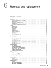
Tray 4 95 Tray 4 driver PCA 95 Power supply 95 Sequence of operation 95 Pickup and feed 96 Media-level and media-size detection 96 Jam detection 96 6 Removal and replacement Introduction 99 Removal ... Paper-input unit (PIU 126 Registration assembly 129 Transfer-guide assembly 131 Left assemblies 133 Duplexer 133 Fuser assembly 134 Back assemblies 135 Formatter 135 Low-voltage power supply 136 High-voltage power supply 137 DC controller 138 Toner-sensor contact assembly 140 Drum motor 141 Feed-drive assembly 142...
Tray 4 95 Tray 4 driver PCA 95 Power supply 95 Sequence of operation 95 Pickup and feed 96 Media-level and media-size detection 96 Jam detection 96 6 Removal and replacement Introduction 99 Removal ... Paper-input unit (PIU 126 Registration assembly 129 Transfer-guide assembly 131 Left assemblies 133 Duplexer 133 Fuser assembly 134 Back assemblies 135 Formatter 135 Low-voltage power supply 136 High-voltage power supply 137 DC controller 138 Toner-sensor contact assembly 140 Drum motor 141 Feed-drive assembly 142...
Service Manual
Page 14
...-removal knob 123 Figure 64. Paper-input unit (1 of 2 156 Figure 107. Duplexer (1 of 2 136 Figure 82. Low-voltage power supply (2 of 2 133 Figure 76. High-voltage power supply (2 of 3 149 Figure 100. Feed-drive assembly 142 Figure 90. Fuser delivery-drive assembly (2 of 2 137 Figure 84...Figure 101. Fuser delivery-drive assembly (3 of 3 148 Figure 98. Cartridge release lever (1 of 2 139 Figure 86. Formatter (HP LaserJet 9000 shown 135 Figure 80. Reinstalling the toner-sensor contact assembly 140 Figure 88. Left side cover 151 Figure 102. Print cartridge 119 Figure...
...-removal knob 123 Figure 64. Paper-input unit (1 of 2 156 Figure 107. Duplexer (1 of 2 136 Figure 82. Low-voltage power supply (2 of 2 133 Figure 76. High-voltage power supply (2 of 3 149 Figure 100. Feed-drive assembly 142 Figure 90. Fuser delivery-drive assembly (2 of 2 137 Figure 84...Figure 101. Fuser delivery-drive assembly (3 of 3 148 Figure 98. Cartridge release lever (1 of 2 139 Figure 86. Formatter (HP LaserJet 9000 shown 135 Figure 80. Reinstalling the toner-sensor contact assembly 140 Figure 88. Left side cover 151 Figure 102. Print cartridge 119 Figure...
Service Manual
Page 85
... sequence 73 Timing chart 74 Engine control system 75 DC controller PCA 76 DC controller operations 77 High-voltage power supply circuit 78 Low-voltage power supply unit 80 Formatter system 81 Formatter hardware 81 Laser/scanner system 83 Image formation system 84 The eight processes of image ...-wrapping-jam detection 87 Jam detection 88 Tray 1 93 Tray 1 driver PCA 93 Power supply 93 Sequence of operation 93 Pickup and feed 94 Jam detection 94 Tray 4 95 Tray 4 driver PCA 95 Power supply 95 Sequence of operation 95 Pickup and feed 96 Media-level and media-size detection...
... sequence 73 Timing chart 74 Engine control system 75 DC controller PCA 76 DC controller operations 77 High-voltage power supply circuit 78 Low-voltage power supply unit 80 Formatter system 81 Formatter hardware 81 Laser/scanner system 83 Image formation system 84 The eight processes of image ...-wrapping-jam detection 87 Jam detection 88 Tray 1 93 Tray 1 driver PCA 93 Power supply 93 Sequence of operation 93 Pickup and feed 94 Jam detection 94 Tray 4 95 Tray 4 driver PCA 95 Power supply 95 Sequence of operation 95 Pickup and feed 96 Media-level and media-size detection...
Service Manual
Page 91
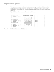
Engine-control-system block diagram Engine control system 75 Figure 24. The engine control system consists of the engine control system. Figure 24 shows a block diagram of the DC controller PCA, the high-voltage power supply circuit, and the low-voltage power supply unit. Engine control system The engine control system coordinates the laser/scanner, image formation, and pickup and feed systems according to the instructions it receives from the formatter.
Engine-control-system block diagram Engine control system 75 Figure 24. The engine control system consists of the engine control system. Figure 24 shows a block diagram of the DC controller PCA, the high-voltage power supply circuit, and the low-voltage power supply unit. Engine control system The engine control system coordinates the laser/scanner, image formation, and pickup and feed systems according to the instructions it receives from the formatter.
Service Manual
Page 96
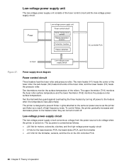
... lower thermistor (TH2) monitors the pressure roller surface temperature. Low-voltage power supply unit The low-voltage power supply unit consists of high-frequency noise. Power-supply-block diagram Fuser control circuit Three heaters heat the fuser roller and pressure roller. Low-voltage power-supply circuit The low-voltage power-supply circuit converts ac voltage from the power source to dc voltage when the printer is designed to the heaters when...
... lower thermistor (TH2) monitors the pressure roller surface temperature. Low-voltage power supply unit The low-voltage power supply unit consists of high-frequency noise. Power-supply-block diagram Fuser control circuit Three heaters heat the fuser roller and pressure roller. Low-voltage power-supply circuit The low-voltage power-supply circuit converts ac voltage from the power source to dc voltage when the printer is designed to the heaters when...
Service Manual
Page 113
... Paper-input unit (PIU 126 Registration assembly 129 Transfer-guide assembly 131 Left assemblies 133 Duplexer 133 Fuser assembly 134 Back assemblies 135 Formatter 135 Low-voltage power supply 136 High-voltage power supply 137 Chapter contents 97
... Paper-input unit (PIU 126 Registration assembly 129 Transfer-guide assembly 131 Left assemblies 133 Duplexer 133 Fuser assembly 134 Back assemblies 135 Formatter 135 Low-voltage power supply 136 High-voltage power supply 137 Chapter contents 97
Service Manual
Page 151
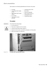
Formatter (HP LaserJet 9000 shown) Back assemblies 135 Back assemblies Gain access to the following assemblies from the formatter. 3 Loosen the two thumb screws (callout 1). 4 Grasp the thumb screws, and slide the formatter out of the printer: z Formatter z Low-voltage power supply (LVPS) z High-voltage power supply (HVPS) z DC controller z Toner-sensor contact assembly z Cartridge memory PCA z Drum motor z Feed-drive...
Formatter (HP LaserJet 9000 shown) Back assemblies 135 Back assemblies Gain access to the following assemblies from the formatter. 3 Loosen the two thumb screws (callout 1). 4 Grasp the thumb screws, and slide the formatter out of the printer: z Formatter z Low-voltage power supply (LVPS) z High-voltage power supply (HVPS) z DC controller z Toner-sensor contact assembly z Cartridge memory PCA z Drum motor z Feed-drive...
Service Manual
Page 152
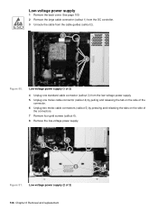
... the cable guides (callout 2). 12 2 Figure 80. See page 109. 2 Remove the large cable connector (callout 1) from the DC controller. 3 Unroute the cable from the low-voltage power supply. 5 Unplug one molex cable connector (callout 4) by pulling and releasing the tab on the side of the connector. 6 Unplug two molex cable connectors (callout 5) by...
... the cable guides (callout 2). 12 2 Figure 80. See page 109. 2 Remove the large cable connector (callout 1) from the DC controller. 3 Unroute the cable from the low-voltage power supply. 5 Unplug one molex cable connector (callout 4) by pulling and releasing the tab on the side of the connector. 6 Unplug two molex cable connectors (callout 5) by...
Service Manual
Page 153
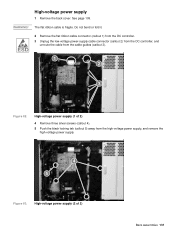
... 2 32 Figure 82. Do not bend or fold it. 2 Remove the flat ribbon cable connector (callout 1) from the DC controller. 3 Unplug the low-voltage power-supply cable connector (callout 2) from the DC controller, and unroute the cable from the high-voltage power supply, and remove the high-voltage power supply. 42 52 Figure 83. High-voltage power supply (1 of 2) Back assemblies 137 WARNING!
... 2 32 Figure 82. Do not bend or fold it. 2 Remove the flat ribbon cable connector (callout 1) from the DC controller. 3 Unplug the low-voltage power-supply cable connector (callout 2) from the DC controller, and unroute the cable from the high-voltage power supply, and remove the high-voltage power supply. 42 52 Figure 83. High-voltage power supply (1 of 2) Back assemblies 137 WARNING!
Service Manual
Page 163
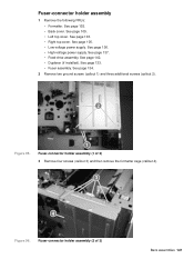
.... 1 Fuser-connector holder assembly (1 of 3) Back assemblies 147 See page 137. • Feed-drive assembly. See page 136. • High-voltage power supply. See page 142. • Duplexer (if installed). See page 105. • Low-voltage power supply. See page 133. • Fuser assembly. See page 135. • Back cover. See page 109. • Left top cover...
.... 1 Fuser-connector holder assembly (1 of 3) Back assemblies 147 See page 137. • Feed-drive assembly. See page 136. • High-voltage power supply. See page 142. • Duplexer (if installed). See page 105. • Low-voltage power supply. See page 133. • Fuser assembly. See page 135. • Back cover. See page 109. • Left top cover...
Service Manual
Page 197
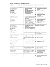
...low setting is necessary. Replace the print cartridge. Replace the DC controller. be loose. The engine is doing an internal No action is 2 set to eject the media). A cleaning page is defective. 1 Remove and reinstall the print cartridge 2 Replace the cartridge. 3 Replace the toner-sensor contact assembly. 4 Replace the high-voltage power supply... pages 4 reaches 0, the message REPLACE CARTRIDGE appears. 5 To continue press . Replace the high-voltage power supply. reached 0%. z The printer continues printing until the drum life reaches 0%. No action is necessary....
...low setting is necessary. Replace the print cartridge. Replace the DC controller. be loose. The engine is doing an internal No action is 2 set to eject the media). A cleaning page is defective. 1 Remove and reinstall the print cartridge 2 Replace the cartridge. 3 Replace the toner-sensor contact assembly. 4 Replace the high-voltage power supply... pages 4 reaches 0, the message REPLACE CARTRIDGE appears. 5 To continue press . Replace the high-voltage power supply. reached 0%. z The printer continues printing until the drum life reaches 0%. No action is necessary....
Service Manual
Page 221
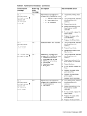
...and then turn the printer on to continue. Resend the print job. Replace the DC controller. 49.X PRINTER ERROR To continue cycle power 49.X A critical firmware error occurred. 1 2 3 Turn off the printer, and then turn the printer on to continue. ...1 corresponds to continue. Replace the upper cable guide assembly. Reseat connections to continue. Replace the upper cableguide assembly. Replace the low-voltage power supply. Numeric error messages (continued) Control panel message Event-log Description error message Recommended action 41.X PRINTER ERROR For help press alternates ...
...and then turn the printer on to continue. Resend the print job. Replace the DC controller. 49.X PRINTER ERROR To continue cycle power 49.X A critical firmware error occurred. 1 2 3 Turn off the printer, and then turn the printer on to continue. ...1 corresponds to continue. Replace the upper cable guide assembly. Reseat connections to continue. Replace the upper cableguide assembly. Replace the low-voltage power supply. Numeric error messages (continued) Control panel message Event-log Description error message Recommended action 41.X PRINTER ERROR For help press alternates ...
Service Manual
Page 273
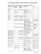
... HP LaserJet 9000 RG5-7780-000CN DC controller HP LaserJet 9040/ 9050 RG5-5728-050CN C8519-69015 High-voltage power supply RG5-5730-000CN C8519-69007 Low-voltage power supply, 110 V HP LaserJet 9000 RG5-7778-000CN Low-voltage power supply, 110 V HP LaserJet 9040/ 9050 RG5-5731-000CN Low-voltage power supply, 220 V HP LaserJet 9000 RG5-7779-000CN Low-voltage power supply, 220 V HP LaserJet 9040/ 9050 RG5-5734-020 Q3721-67902 Control panel assembly HP LaserJet 9040/ 9050 Q2635-67912 Firmware Compact Flash HP LaserJet...
... HP LaserJet 9000 RG5-7780-000CN DC controller HP LaserJet 9040/ 9050 RG5-5728-050CN C8519-69015 High-voltage power supply RG5-5730-000CN C8519-69007 Low-voltage power supply, 110 V HP LaserJet 9000 RG5-7778-000CN Low-voltage power supply, 110 V HP LaserJet 9040/ 9050 RG5-5731-000CN Low-voltage power supply, 220 V HP LaserJet 9000 RG5-7779-000CN Low-voltage power supply, 220 V HP LaserJet 9040/ 9050 RG5-5734-020 Q3721-67902 Control panel assembly HP LaserJet 9040/ 9050 Q2635-67912 Firmware Compact Flash HP LaserJet...
Service Manual
Page 289
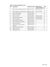
Internal components (4 of 4) Ref Description 9000 part number 9040/9050 part Qty number (if different) 1 Low voltage power supply assembly 110 V RG5-5730-000CN RG5-7778-000CN 1 1 Low voltage power supply assembly 220 V RG5-5731-000CN RG5-7779-000CN 1 2 Cable, HVPS flat ribbon RH2-5445-000CN 1 3 Fan, #1, power supply RH7-5294-000CN 1 4 Fan, #2, controller RH7-5295-000CN RH7-1623-000CN 1 5 Back cable...
Internal components (4 of 4) Ref Description 9000 part number 9040/9050 part Qty number (if different) 1 Low voltage power supply assembly 110 V RG5-5730-000CN RG5-7778-000CN 1 1 Low voltage power supply assembly 220 V RG5-5731-000CN RG5-7779-000CN 1 2 Cable, HVPS flat ribbon RH2-5445-000CN 1 3 Fan, #1, power supply RH7-5294-000CN 1 4 Fan, #2, controller RH7-5295-000CN RH7-1623-000CN 1 5 Back cable...
Service Manual
Page 309
... upper cover assembly Lever, custom Lever, sensor Lever, switch Link, connect Low voltage power supply assembly 110 V (HP LaserJet 9040/9050) Low voltage power supply assembly 110 V (HP LaserJet 9000) Low voltage power supply assembly 220 V (HP LaserJet 9040/9050) Low voltage power supply assembly 220 V (HP LaserJet 9000) Main cable harness holder assembly Main motor (M2) Microswitch (SW1) Motor Motor, DC, 24V (M1) (HP LaserJet 9040/9050) Part number RG5-5700-000CN RG5-5771-000CN RS5-0708...
... upper cover assembly Lever, custom Lever, sensor Lever, switch Link, connect Low voltage power supply assembly 110 V (HP LaserJet 9040/9050) Low voltage power supply assembly 110 V (HP LaserJet 9000) Low voltage power supply assembly 220 V (HP LaserJet 9040/9050) Low voltage power supply assembly 220 V (HP LaserJet 9000) Main cable harness holder assembly Main motor (M2) Microswitch (SW1) Motor Motor, DC, 24V (M1) (HP LaserJet 9040/9050) Part number RG5-5700-000CN RG5-5771-000CN RS5-0708...
Service Manual
Page 314
... RG5-5724-000CN Fusing connector holder assembly RG5-5725-000CN Back cable holder assembly (HP LaserJet 9000) RG5-5727-000CN Inlet assembly (Power SW 10) RG5-5728-050CN High voltage power supply (HVPS) RG5-5730-000CN Low voltage power supply assembly 110 V (HP LaserJet 9000) RG5-5731-000CN Low voltage power supply assembly 220 V (HP LaserJet 9040/9050) RG5-5737-000CN Right cover assembly RG5-5740-000CN Right cover knob...
... RG5-5724-000CN Fusing connector holder assembly RG5-5725-000CN Back cable holder assembly (HP LaserJet 9000) RG5-5727-000CN Inlet assembly (Power SW 10) RG5-5728-050CN High voltage power supply (HVPS) RG5-5730-000CN Low voltage power supply assembly 110 V (HP LaserJet 9000) RG5-5731-000CN Low voltage power supply assembly 220 V (HP LaserJet 9040/9050) RG5-5737-000CN Right cover assembly RG5-5740-000CN Right cover knob...
Service Manual
Page 315
...-7778-000CN Low voltage power supply assembly 110 V (HP LaserJet 9040/9050) RG5-7779-000CN Low voltage power supply assembly 220 V (HP LaserJet 9040/9050) RG5-7780-120CN DC controller PCA RG5-7783-000CN Fan connecting cable (HP LaserJet 9040/9050) RG5-7786-000CN Back cable holder assembly (HP LaserJet 9040/9050)...1622-000CN Motor, DC, 24V (M1) (HP LaserJet 9040/9050) RH7-1623-000CN Fan, #2, controller (HP LaserJet 9040/9050) RH7-5287-000CN Main motor (M2) RH7-5294-000CN Fan, #1, power supply RH7-5295-000CN Fan, #2, controller (HP LaserJet 9000) RH7-5296-000CN Fan, #3, rear delivery ...
...-7778-000CN Low voltage power supply assembly 110 V (HP LaserJet 9040/9050) RG5-7779-000CN Low voltage power supply assembly 220 V (HP LaserJet 9040/9050) RG5-7780-120CN DC controller PCA RG5-7783-000CN Fan connecting cable (HP LaserJet 9040/9050) RG5-7786-000CN Back cable holder assembly (HP LaserJet 9040/9050)...1622-000CN Motor, DC, 24V (M1) (HP LaserJet 9040/9050) RH7-1623-000CN Fan, #2, controller (HP LaserJet 9040/9050) RH7-5287-000CN Main motor (M2) RH7-5294-000CN Fan, #1, power supply RH7-5295-000CN Fan, #2, controller (HP LaserJet 9000) RH7-5296-000CN Fan, #3, rear delivery ...
Service Manual
Page 322
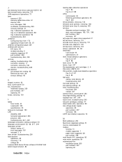
... languages, printer default, setting 47 error messages 181 included 2, 4 laser shutter, troubleshooting 236 laser/scanner operations 83 removing 112 voltage 80 LaserJet 9000 Series Printer software CD-ROM 260 latent image formation 84 Index306 Index leading edge, detection operations tray 1 94 tray 2 or ...control panel 180 long edge binding, settings 42 loopback test 247, 249 loose toner, troubleshooting 240 low print cartridges, settings 47 lower heater (H3), operations 80 low-voltage power supply operations 80 part numbers 257 removing 136 LSTR (last rotation) sequence 72 M MAC addresses 250...
... languages, printer default, setting 47 error messages 181 included 2, 4 laser shutter, troubleshooting 236 laser/scanner operations 83 removing 112 voltage 80 LaserJet 9000 Series Printer software CD-ROM 260 latent image formation 84 Index306 Index leading edge, detection operations tray 1 94 tray 2 or ...control panel 180 long edge binding, settings 42 loopback test 247, 249 loose toner, troubleshooting 240 low print cartridges, settings 47 lower heater (H3), operations 80 low-voltage power supply operations 80 part numbers 257 removing 136 LSTR (last rotation) sequence 72 M MAC addresses 250...
Service Manual
Page 324
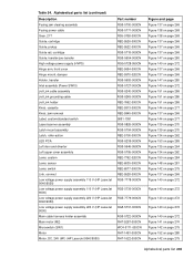
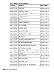
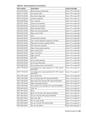
...operations bias generation circuits 79 DC controller 76 engine control system 75 formatter 81 high-voltage power supply circuit 78 image formation 84 laser/scanner system 83 low-voltage power supply 80 pickup and feed system 87 power-on 73 sequences 71 systems overview 70 tray 1 93 tray 4 95 ordering parts... input submenu 48 parallel port, supported 3, 5 part numbers alphabetical list 291 consumables, accessories, and documentation 257 numerical list 296 voltage 256 parts ordering 14 removing and replacing 99 Pause/Resume key, control panel 31 pay-per-page 231 PCB assemblies, diagrams and...
...operations bias generation circuits 79 DC controller 76 engine control system 75 formatter 81 high-voltage power supply circuit 78 image formation 84 laser/scanner system 83 low-voltage power supply 80 pickup and feed system 87 power-on 73 sequences 71 systems overview 70 tray 1 93 tray 4 95 ordering parts... input submenu 48 parallel port, supported 3, 5 part numbers alphabetical list 291 consumables, accessories, and documentation 257 numerical list 296 voltage 256 parts ordering 14 removing and replacing 99 Pause/Resume key, control panel 31 pay-per-page 231 PCB assemblies, diagrams and...

