Service Manual
Page 87
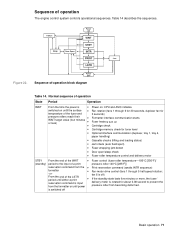
...fuser roller temperature-180°C [356°F]/ pressure roller 140°C [285°F]) Print reservation command (awaits INTR sequence) Fan-motor drive control (fans 1 through 6 for 30 seconds, duplexer fan for 3 seconds) Formatter interface communication starts Fuser heaters turn on ...the LSTR period until either a print z reservation command is rotated for toner level Optional interface communication (duplexer, tray 1, tray 4, paper handling) Cassette checks (lifting and loading status) Jam check (auto flush/eject) Fuser-wrapping-jam detect Door open/sleep check Fuser-roller ...
...fuser roller temperature-180°C [356°F]/ pressure roller 140°C [285°F]) Print reservation command (awaits INTR sequence) Fan-motor drive control (fans 1 through 6 for 30 seconds, duplexer fan for 3 seconds) Formatter interface communication starts Fuser heaters turn on ...the LSTR period until either a print z reservation command is rotated for toner level Optional interface communication (duplexer, tray 1, tray 4, paper handling) Cassette checks (lifting and loading status) Jam check (auto flush/eject) Fuser-wrapping-jam detect Door open/sleep check Fuser-roller ...
Service Manual
Page 110
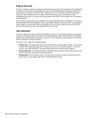
...After completing one rotation, the cam contacts the stopper and is held in the tray, and then separating the roller from each other. The CPU in the reverse direction from the media surface the pickup cam lifts the pickup roller up and down . The paper path sensor (PS2502) does not... the specified length of time after the start of the second motor rotation. When a multifeed occurs, the torque limiter allows the top sheet to feed into the printer, but returns the additional sheet to rotate. Jam detection The tray 1 paper path sensor (PS2502) determines whether or not media ...
...After completing one rotation, the cam contacts the stopper and is held in the tray, and then separating the roller from each other. The CPU in the reverse direction from the media surface the pickup cam lifts the pickup roller up and down . The paper path sensor (PS2502) does not... the specified length of time after the start of the second motor rotation. When a multifeed occurs, the torque limiter allows the top sheet to feed into the printer, but returns the additional sheet to rotate. Jam detection The tray 1 paper path sensor (PS2502) determines whether or not media ...
Service Manual
Page 111
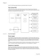
... switch method for standalone diagnostics. The power unit utilizes a standalone switch so that controls the tray 4 operational sequence and serial communications with media and closed, the paper deck starts lifting the stack to the pickup position. The +5 V is supplied to the sensors and also ...to the driver PCA. +24V is then supplied to the lifter, feed, and pickup motors to the registration assembly. Tray 4 95 See "Tray 4 diagnostics" in tray 4 holds a 16-bit microcomputer (IC1) that tray 4 can be powered on without turning on the driver PCA. The driver PCA drives the...
... switch method for standalone diagnostics. The power unit utilizes a standalone switch so that controls the tray 4 operational sequence and serial communications with media and closed, the paper deck starts lifting the stack to the pickup position. The +5 V is supplied to the sensors and also ...to the driver PCA. +24V is then supplied to the lifter, feed, and pickup motors to the registration assembly. Tray 4 95 See "Tray 4 diagnostics" in tray 4 holds a 16-bit microcomputer (IC1) that tray 4 can be powered on without turning on the driver PCA. The driver PCA drives the...
Service Manual
Page 147
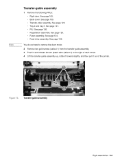
See page 105. • Back cover. See page 142. See page 121. • PIU. See page 120. • Tray 2 and tray 3. See page 129. • Fuser assembly. Transfer-guide assembly Right assemblies 131 See page 109. • Transfer-roller assembly. See page 134. • Feed-...126. • Registration assembly. You do not need to remove the drum motor. 2 Remove two gold screws (callout 1) from the transfer-guide assembly. 3 Push in and release the two plastic tabs (callout 2) to the right of each screw. 4 Lift the transfer-guide assembly up, rotate it forward slightly, and then pull it...
See page 105. • Back cover. See page 142. See page 121. • PIU. See page 120. • Tray 2 and tray 3. See page 129. • Fuser assembly. Transfer-guide assembly Right assemblies 131 See page 109. • Transfer-roller assembly. See page 134. • Feed-...126. • Registration assembly. You do not need to remove the drum motor. 2 Remove two gold screws (callout 1) from the transfer-guide assembly. 3 Push in and release the two plastic tabs (callout 2) to the right of each screw. 4 Lift the transfer-guide assembly up, rotate it forward slightly, and then pull it...
Service Manual
Page 167
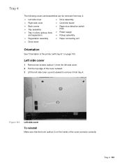
... assemblies can be removed from tray 4: z Left side cover z Right side cover z Back covers z Tray assembly z Tray 4 rollers (pickup, feed, and separation) z Registration assembly z Drive motor z Drive assembly z Controller board z Paper-size detection switch PCB z Power supply z Pickup assembly z Paper connecting unit Orientation See "Orientation of the cover outward. 3 Lift the left side cover up...
... assemblies can be removed from tray 4: z Left side cover z Right side cover z Back covers z Tray assembly z Tray 4 rollers (pickup, feed, and separation) z Registration assembly z Drive motor z Drive assembly z Controller board z Paper-size detection switch PCB z Power supply z Pickup assembly z Paper connecting unit Orientation See "Orientation of the cover outward. 3 Lift the left side cover up...
Service Manual
Page 238
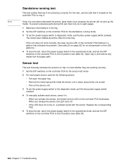
... paper sensor, perform the following actions: • Pull open the paper tray. • Remove the metal spring that tray 4 is mounted underneath the printer, jams might occur because the printer will not pick up the media. The motors start. If the unit does not work correctly, the lower service LED... set the power-supply switch to diagnostic mode, pull the blue power-supply switch outward. Media should be lifted from the paper path. When you activate the sensor, the bottom service LED on tray 4. For this test, feed only six to eight pages. 1 Make sure that indicates the problem. (...
... paper sensor, perform the following actions: • Pull open the paper tray. • Remove the metal spring that tray 4 is mounted underneath the printer, jams might occur because the printer will not pick up the media. The motors start. If the unit does not work correctly, the lower service LED... set the power-supply switch to diagnostic mode, pull the blue power-supply switch outward. Media should be lifted from the paper path. When you activate the sensor, the bottom service LED on tray 4. For this test, feed only six to eight pages. 1 Make sure that indicates the problem. (...
Service Manual
Page 239
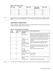
...it picks up media from the tray and feeds it lifts smoothly. wrong size of media Load the correct size of media, or check the sensors. Tray 4 diagnostics 223 Note Note Table 24. Tray 4 light-pattern interpretation Long (1...media. DIP switch settings DIP switch Normal 1 Off 2 Off 3 Off 4 Off Motor test On On Off On Stand-alone running test On Off Off On Sensor test... will not work correctly. lifter malfunction Make sure that the paper-size plates are correctly installed (in tray Load the media, or check the sensors. Replace the paper pickup delay jam assembly. 2 2 13...
...it picks up media from the tray and feeds it lifts smoothly. wrong size of media Load the correct size of media, or check the sensors. Tray 4 diagnostics 223 Note Note Table 24. Tray 4 light-pattern interpretation Long (1...media. DIP switch settings DIP switch Normal 1 Off 2 Off 3 Off 4 Off Motor test On On Off On Stand-alone running test On Off Off On Sensor test... will not work correctly. lifter malfunction Make sure that the paper-size plates are correctly installed (in tray Load the media, or check the sensors. Replace the paper pickup delay jam assembly. 2 2 13...


