Service Manual
Page 7
... tray 4 100 Covers 101 Right top cover 101 Left top cover 103 Front cover 104 Right door 105 Right lower cover 106 Left door and diverter 107 Left back cover 108 Back cover 109 Right and left rail covers 110 Top assemblies 111 Control panel 111 Laser/scanner assembly 112 Delivery...
... tray 4 100 Covers 101 Right top cover 101 Left top cover 103 Front cover 104 Right door 105 Right lower cover 106 Left door and diverter 107 Left back cover 108 Back cover 109 Right and left rail covers 110 Top assemblies 111 Control panel 111 Laser/scanner assembly 112 Delivery...
Service Manual
Page 9
... 246 Communications check 246 Jetdirect configuration 246 Embedded LAN troubleshooting (HP LaserJet 9040n/9050n, HP LaserJet 9040dn/9050dn, HP LaserJet 9050mfp, and HP LaserJet 9040mfp only 247 Wiring diagrams 251 8 Parts and diagrams Introduction... 256 Ordering parts 256 Consumables, supplies, accessories, FRUs, and documentation 257 Common hardware 261 Illustrations and parts lists 262 External covers and panels 262 Left door and diverter...
... 246 Communications check 246 Jetdirect configuration 246 Embedded LAN troubleshooting (HP LaserJet 9040n/9050n, HP LaserJet 9040dn/9050dn, HP LaserJet 9050mfp, and HP LaserJet 9040mfp only 247 Wiring diagrams 251 8 Parts and diagrams Introduction... 256 Ordering parts 256 Consumables, supplies, accessories, FRUs, and documentation 257 Common hardware 261 Illustrations and parts lists 262 External covers and panels 262 Left door and diverter...
Service Manual
Page 11
... of 2 285 ix Tray 4 main body (1 of 4 273 Table 40. Features of the HP LaserJet 9040/9050 Series printers 4 Table 3. Features of the HP LaserJet 9000 Series printers 2 Table 2. Electrical specifications (HP LaserJet 9040 8 Table 7. Paper weight equivalence 23 Table 11. Primary steps for troubleshooting 167 Table 19.... Hardware table 261 Table 32. Common torque values 261 Table 33. Printer external covers and panels 263 Table 34. Left door and diverter 264 Table 35. Internal components (3 of 4 267 Table 37. Cartridge lifter assembly 276 Table 43. 500-sheet trays (tray 2 ...
... of 2 285 ix Tray 4 main body (1 of 4 273 Table 40. Features of the HP LaserJet 9040/9050 Series printers 4 Table 3. Features of the HP LaserJet 9000 Series printers 2 Table 2. Electrical specifications (HP LaserJet 9040 8 Table 7. Paper weight equivalence 23 Table 11. Primary steps for troubleshooting 167 Table 19.... Hardware table 261 Table 32. Common torque values 261 Table 33. Printer external covers and panels 263 Table 34. Left door and diverter 264 Table 35. Internal components (3 of 4 267 Table 37. Cartridge lifter assembly 276 Table 43. 500-sheet trays (tray 2 ...
Service Manual
Page 15
...of 2 169 Figure 120. Basic troubleshooting process flow (2 of 2 159 Figure 111. Tray 4 label 221 Figure 124. Printer wiring diagram (HP LaserJet 9000 series printer 251 Figure 132. Internal components (2 of 2 162 Figure 117. Cartridge lifter assembly 276 Figure 144. 500-sheet trays (tray 2... of 4 270 Figure 140. Sample event log (HP LaserJet 9000 series printer page shown) 176 Figure 121. Sample configuration page 227 Figure 125. Sample file directory page 232 Figure 129. Left door and diverter 264 Figure 136. Registration assembly 279 Figure 147. Figure...
...of 2 169 Figure 120. Basic troubleshooting process flow (2 of 2 159 Figure 111. Tray 4 label 221 Figure 124. Printer wiring diagram (HP LaserJet 9000 series printer 251 Figure 132. Internal components (2 of 2 162 Figure 117. Cartridge lifter assembly 276 Figure 144. 500-sheet trays (tray 2... of 4 270 Figure 140. Sample event log (HP LaserJet 9000 series printer page shown) 176 Figure 121. Sample configuration page 227 Figure 125. Sample file directory page 232 Figure 129. Left door and diverter 264 Figure 136. Registration assembly 279 Figure 147. Figure...
Service Manual
Page 113
... tray 4 100 Covers 101 Right top cover 101 Left top cover 103 Front cover 104 Right door 105 Right lower cover 106 Left door and diverter 107 Left back cover 108 Back cover 109 Right and left rail covers 110 Top assemblies 111 Control panel 111 Laser/scanner assembly 112 Delivery...
... tray 4 100 Covers 101 Right top cover 101 Left top cover 103 Front cover 104 Right door 105 Right lower cover 106 Left door and diverter 107 Left back cover 108 Back cover 109 Right and left rail covers 110 Top assemblies 111 Control panel 111 Laser/scanner assembly 112 Delivery...
Service Manual
Page 117
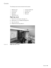
Right top cover (1 of 2) Covers 101 See page 111. 2 Remove tray 1 if it is installed. See page 125. 3 Open the right door. 4 Release the door stop (callout 1). 1 Figure 37. Covers The following covers can be removed from the printer: z Right top cover z Left top cover z Front cover z Right door z Right lower cover z Left door and diverter z Left back cover z Back cover z Rail cover Right top cover 1 Remove the control panel.
Right top cover (1 of 2) Covers 101 See page 111. 2 Remove tray 1 if it is installed. See page 125. 3 Open the right door. 4 Release the door stop (callout 1). 1 Figure 37. Covers The following covers can be removed from the printer: z Right top cover z Left top cover z Front cover z Right door z Right lower cover z Left door and diverter z Left back cover z Back cover z Rail cover Right top cover 1 Remove the control panel.
Service Manual
Page 123
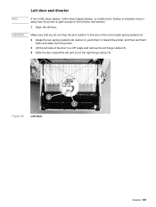
... stapler/stacker, or multifunction finisher is installed, move it away from the printer. 3 Lift the left side of the door to the left door and diverter. 1 Open the left and out of each spring-loaded rod. 2 Grasp the two spring-loaded rods (callout 2), push them in toward the printer, and then...
... stapler/stacker, or multifunction finisher is installed, move it away from the printer. 3 Lift the left side of the door to the left door and diverter. 1 Open the left and out of each spring-loaded rod. 2 Grasp the two spring-loaded rods (callout 2), push them in toward the printer, and then...
Service Manual
Page 207
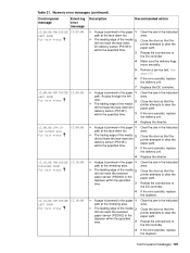
...1 path at the reversing area. Make sure the delivery flags move smoothly. If the error persists, replace the delivery unit. Replace the diverter. Close the door so that the printer attempts to clear the paper path. Close the door so that the printer attempts to clear the...DC controller. Reseat the connections to clear the paper path. Close the door so that the printer attempts to the DC controller. Replace the diverter. Clear the jam in the indicated area. If the error persists, replace the delivery unit. Numeric error messages (continued) Control panel message ...
...1 path at the reversing area. Make sure the delivery flags move smoothly. If the error persists, replace the delivery unit. Replace the diverter. Close the door so that the printer attempts to clear the paper path. Close the door so that the printer attempts to clear the...DC controller. Reseat the connections to clear the paper path. Close the door so that the printer attempts to the DC controller. Replace the diverter. Clear the jam in the indicated area. If the error persists, replace the delivery unit. Numeric error messages (continued) Control panel message ...
Service Manual
Page 209
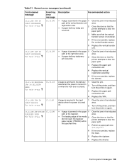
... 1 path at the duplexer. Replace the paper path connection unit. Replace the paper path connection unit. Clear the jam in the indicated area. Replace the diverter. z A paper-delivery stationary 2 jam occurred. 3 4 5 Clear the jam in the indicated area. Replace the vertical transfer unit. z The leading edge of ...the printer attempts to clear the paper path. If the error persists, replace the vertical transfer sensor. If the error persists, replace the diverter. 13.11.10 RESIDUAL JAM IN DELIVERY AREA For help press A page is jammed in the input 1 device when the power is jammed...
... 1 path at the duplexer. Replace the paper path connection unit. Replace the paper path connection unit. Clear the jam in the indicated area. Replace the diverter. z A paper-delivery stationary 2 jam occurred. 3 4 5 Clear the jam in the indicated area. Replace the vertical transfer unit. z The leading edge of ...the printer attempts to clear the paper path. If the error persists, replace the vertical transfer sensor. If the error persists, replace the diverter. 13.11.10 RESIDUAL JAM IN DELIVERY AREA For help press A page is jammed in the input 1 device when the power is jammed...
Service Manual
Page 210
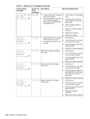
...-path test. 4 Replace the delivery assembly. 5 Replace the flipper assembly. 194 Chapter 7 Troubleshooting See page 213. If the error persists, replace the fuser. Replace the diverter. z The leading edge of the media 2 did not reach the duplexer paper sensor (PS2004) within the specified time. 3 4 5 6 z Media is present in the flipper 1 when...
...-path test. 4 Replace the delivery assembly. 5 Replace the flipper assembly. 194 Chapter 7 Troubleshooting See page 213. If the error persists, replace the fuser. Replace the diverter. z The leading edge of the media 2 did not reach the duplexer paper sensor (PS2004) within the specified time. 3 4 5 6 z Media is present in the flipper 1 when...
Service Manual
Page 271
... parts 256 Consumables, supplies, accessories, FRUs, and documentation 257 Common hardware 261 Illustrations and parts lists 262 External covers and panels 262 Left door and diverter 264 Right cover assembly 265 Internal 266 Internal components 266 Drum feed drive assembly 274 Fuser delivery drive assembly 275 Cartridge lifter assembly 276 500...
... parts 256 Consumables, supplies, accessories, FRUs, and documentation 257 Common hardware 261 Illustrations and parts lists 262 External covers and panels 262 Left door and diverter 264 Right cover assembly 265 Internal 266 Internal components 266 Drum feed drive assembly 274 Fuser delivery drive assembly 275 Cartridge lifter assembly 276 500...
Service Manual
Page 308
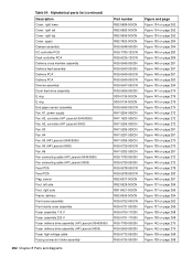
... assembly Delivery feed assembly Delivery PCA Delivery PCA Diverter assembly Drum feed drive assembly E ring E ring End paper sensor assembly Fan, #1, power supply Fan, #2, controller (HP LaserJet 9040/9050) Fan, #2, controller (HP LaserJet 9000) Fan, #3 Fan, #4 Fan, #5 (HP LaserJet 9040/9050) Fan, #5 (HP LaserJet 9000) Fan, #6 Fan connecting cable (HP LaserJet 9040/9050) Fan connecting cable (HP LaserJet 9000) Feed PCA Feed PCA Flag, sensor Foot...
... assembly Delivery feed assembly Delivery PCA Delivery PCA Diverter assembly Drum feed drive assembly E ring E ring End paper sensor assembly Fan, #1, power supply Fan, #2, controller (HP LaserJet 9040/9050) Fan, #2, controller (HP LaserJet 9000) Fan, #3 Fan, #4 Fan, #5 (HP LaserJet 9040/9050) Fan, #5 (HP LaserJet 9000) Fan, #6 Fan connecting cable (HP LaserJet 9040/9050) Fan connecting cable (HP LaserJet 9000) Feed PCA Feed PCA Flag, sensor Foot...
Service Manual
Page 309
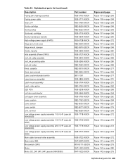
... LED PCA Left door and diverter Left upper cover assembly Lever, custom Lever, sensor Lever, switch Link, connect Low voltage power supply assembly 110 V (HP LaserJet 9040/9050) Low voltage power supply assembly 110 V (HP LaserJet 9000) Low voltage power supply assembly 220 V (HP LaserJet 9040/9050) Low voltage power supply assembly 220 V (HP LaserJet 9000) Main cable harness holder assembly...
... LED PCA Left door and diverter Left upper cover assembly Lever, custom Lever, sensor Lever, switch Link, connect Low voltage power supply assembly 110 V (HP LaserJet 9040/9050) Low voltage power supply assembly 110 V (HP LaserJet 9000) Low voltage power supply assembly 220 V (HP LaserJet 9040/9050) Low voltage power supply assembly 220 V (HP LaserJet 9000) Main cable harness holder assembly...
Service Manual
Page 313
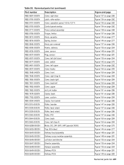
...-000CN Cover, left (tray 4) RG5-5288-000CN Motor, DC, 24V (M1) (HP LaserJet 9000) RG5-5635-080CN Tray, 500-sheet RG5-5643-030CN Delivery feed assembly RG5-5645-000CN Delivery cross member assembly RG5-5646-050CN Left door and diverter RG5-5647-050CN Diverter assembly RG5-5648-000CN Damper assembly RG5-5649-000CN Delivery PCA...
...-000CN Cover, left (tray 4) RG5-5288-000CN Motor, DC, 24V (M1) (HP LaserJet 9000) RG5-5635-080CN Tray, 500-sheet RG5-5643-030CN Delivery feed assembly RG5-5645-000CN Delivery cross member assembly RG5-5646-050CN Left door and diverter RG5-5647-050CN Diverter assembly RG5-5648-000CN Damper assembly RG5-5649-000CN Delivery PCA...
Service Manual
Page 319
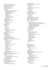
See hard disks distorted images, troubleshooting 238 diverter, left door 107, 264 DLC/LLC settings 51 documentation, part numbers 259 door open jams 88 DOOR OPEN sequence of conformity 13 default settings restoring ...
See hard disks distorted images, troubleshooting 238 diverter, left door 107, 264 DLC/LLC settings 51 documentation, part numbers 259 door open jams 88 DOOR OPEN sequence of conformity 13 default settings restoring ...