Service Manual
Page 7
... of operation 95 Pickup and feed 96 Media-level and media-size detection 96 Jam detection 96 6 Removal and replacement Introduction 99 Removal and replacement strategy 99 Repair notices 99 Electrostatic discharge (ESD 99 Required tools 99 Orientation of the printer (with tray 4 ...and left rail covers 110 Top assemblies 111 Control panel 111 Laser/scanner assembly 112 Delivery assembly 113 Delivery-fan assembly 114 Delivery-assembly fans and face-down-bin fan (fans 3, 6, and 4 115 Delivery motor 116 Cartridge release lever 117 Front assemblies 119 Print cartridge 119 Transfer...
... of operation 95 Pickup and feed 96 Media-level and media-size detection 96 Jam detection 96 6 Removal and replacement Introduction 99 Removal and replacement strategy 99 Repair notices 99 Electrostatic discharge (ESD 99 Required tools 99 Orientation of the printer (with tray 4 ...and left rail covers 110 Top assemblies 111 Control panel 111 Laser/scanner assembly 112 Delivery assembly 113 Delivery-fan assembly 114 Delivery-assembly fans and face-down-bin fan (fans 3, 6, and 4 115 Delivery motor 116 Cartridge release lever 117 Front assemblies 119 Print cartridge 119 Transfer...
Service Manual
Page 113
... contents Introduction 99 Removal and replacement strategy 99 Repair notices 99 Electrostatic discharge (ESD 99 Required tools 99 Orientation of the printer (with tray 4 100 Covers 101 Right top cover 101 ... 109 Right and left rail covers 110 Top assemblies 111 Control panel 111 Laser/scanner assembly 112 Delivery assembly 113 Delivery-fan assembly 114 Delivery-assembly fans and face-down-bin fan (fans 3, 6, and 4 115 Delivery motor 116 Cartridge release lever 117 Front assemblies 119 Print cartridge 119 Transfer-roller assembly 120 Tray 2 and...
... contents Introduction 99 Removal and replacement strategy 99 Repair notices 99 Electrostatic discharge (ESD 99 Required tools 99 Orientation of the printer (with tray 4 100 Covers 101 Right top cover 101 ... 109 Right and left rail covers 110 Top assemblies 111 Control panel 111 Laser/scanner assembly 112 Delivery assembly 113 Delivery-fan assembly 114 Delivery-assembly fans and face-down-bin fan (fans 3, 6, and 4 115 Delivery motor 116 Cartridge release lever 117 Front assemblies 119 Print cartridge 119 Transfer-roller assembly 120 Tray 2 and...
Service Manual
Page 114
DC controller 138 Toner-sensor contact assembly 140 Drum motor 141 Drum motor 141 Feed-drive assembly 142 Power-supply fan (fan 1 143 Cartridge fan (fan 5 144 Controller fan (fan 2 145 Jetlink connector 146 Fuser-connector holder assembly 147 Fuser delivery-drive assembly 149 Tray 4 151 Orientation 151 Left side cover 151 Right side cover ... assembly 158 Controller board 159 Paper-size detection switch PCA 160 Power supply 161 Pickup assembly 162 Paper-connecting unit 163 98 Chapter 6 Removal and replacement
DC controller 138 Toner-sensor contact assembly 140 Drum motor 141 Drum motor 141 Feed-drive assembly 142 Power-supply fan (fan 1 143 Cartridge fan (fan 5 144 Controller fan (fan 2 145 Jetlink connector 146 Fuser-connector holder assembly 147 Fuser delivery-drive assembly 149 Tray 4 151 Orientation 151 Left side cover 151 Right side cover ... assembly 158 Controller board 159 Paper-size detection switch PCA 160 Power supply 161 Pickup assembly 162 Paper-connecting unit 163 98 Chapter 6 Removal and replacement
Service Manual
Page 130
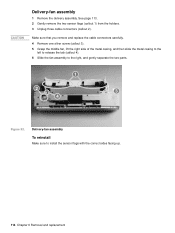
...callout 1) from the holders. 3 Unplug three cable connectors (callout 2). Delivery-fan assembly To reinstall Make sure to the right, and gently separate the two parts. 21 2 32 42 Figure 52. Make sure that you remove and replace the cable connectors carefully. 4 Remove one silver screw (callout 3). 5 Grasp... the middle fan, lift the right side of the metal casing, and then slide the metal casing to the left ...
...callout 1) from the holders. 3 Unplug three cable connectors (callout 2). Delivery-fan assembly To reinstall Make sure to the right, and gently separate the two parts. 21 2 32 42 Figure 52. Make sure that you remove and replace the cable connectors carefully. 4 Remove one silver screw (callout 3). 5 Grasp... the middle fan, lift the right side of the metal casing, and then slide the metal casing to the left ...
Service Manual
Page 131
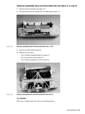
... replace each fan in the correct airflow position. Top assemblies 115 Delivery-assembly fans and face-down -bin fan (2 of 2) 3 Remove six gold screws (callout 2). 4 Remove the three fans: • Fan 3: delivery-assembly back fan (callout 3) • Fan 6: face-down-bin fan (callout 4) • Fan 4: delivery-assembly front fan (callout 5) 2 Figure 54. 23 42 52 Delivery-assembly fans and face-down -bin fan (fans...
... replace each fan in the correct airflow position. Top assemblies 115 Delivery-assembly fans and face-down -bin fan (2 of 2) 3 Remove six gold screws (callout 2). 4 Remove the three fans: • Fan 3: delivery-assembly back fan (callout 3) • Fan 6: face-down-bin fan (callout 4) • Fan 4: delivery-assembly front fan (callout 5) 2 Figure 54. 23 42 52 Delivery-assembly fans and face-down -bin fan (fans...
Service Manual
Page 160
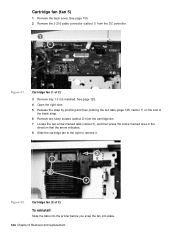
... 2) To reinstall Slide the tabs into the printer before you snap the fan into place. 144 Chapter 6 Removal and replacement See page 125. 4 Open the right door. 5 Release the strap by pinching and then pushing the two tabs (page 105, callout 1) on the end of ...the black strap. 6 Remove two silver screws (callout 2) from the DC controller. 12 Figure 91. Cartridge fan (2 of 2) 3 Remove tray 1 if it . 23 2 Figure 92. Cartridge fan (fan...
... 2) To reinstall Slide the tabs into the printer before you snap the fan into place. 144 Chapter 6 Removal and replacement See page 125. 4 Open the right door. 5 Release the strap by pinching and then pushing the two tabs (page 105, callout 1) on the end of ...the black strap. 6 Remove two silver screws (callout 2) from the DC controller. 12 Figure 91. Cartridge fan (2 of 2) 3 Remove tray 1 if it . 23 2 Figure 92. Cartridge fan (fan...
Service Manual
Page 190
...MENU to the DC controller PCA. 2 Perform an engine test. See "Electrical specifications (HP LaserJet 9000)" in locating printing errors. Then, turn off switch set to Push the switch to half-speed, and fan 6 stops during the WAIT period. If the engine test is still unsuccessful, perform ...not working , but the printer control panel is functional. Make sure that the latest firmware is installed. 4 Replace the printer formatter PCA. Are the printer fans on ? If the fans are generated). 3 The DC controller PCA microprocessor is blank, print an engine test. Is the printer on ...
...MENU to the DC controller PCA. 2 Perform an engine test. See "Electrical specifications (HP LaserJet 9000)" in locating printing errors. Then, turn off switch set to Push the switch to half-speed, and fan 6 stops during the WAIT period. If the engine test is still unsuccessful, perform ...not working , but the printer control panel is functional. Make sure that the latest firmware is installed. 4 Replace the printer formatter PCA. Are the printer fans on ? If the fans are generated). 3 The DC controller PCA microprocessor is blank, print an engine test. Is the printer on ...
Service Manual
Page 223
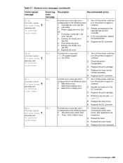
...fan error (fan #5) 2 (not used) 3 Power-supply-fan error (fan 2 #1) 4 Formatter- (controller-) fan error (fan #2) 3 5 Delivery-fan (front) error (fan #4) 4 6 Face-down tray error 7 Delivery-fan (back) error (fan #3) 8 Duplexer-fan error Turn off the printer, and then turn the printer on again to continue. 2 Check the printer configuration. 3 Replace the print cartridge. 4 Replace...motor, and reseat them as necessary. If the error persists, replace the specified fan. Table 21. Replace the print cartridge. Replace the DC controller. 58.XX PRINTER ERROR For help press ...
...fan error (fan #5) 2 (not used) 3 Power-supply-fan error (fan 2 #1) 4 Formatter- (controller-) fan error (fan #2) 3 5 Delivery-fan (front) error (fan #4) 4 6 Face-down tray error 7 Delivery-fan (back) error (fan #3) 8 Duplexer-fan error Turn off the printer, and then turn the printer on again to continue. 2 Check the printer configuration. 3 Replace the print cartridge. 4 Replace...motor, and reseat them as necessary. If the error persists, replace the specified fan. Table 21. Replace the print cartridge. Replace the DC controller. 58.XX PRINTER ERROR For help press ...
Service Manual
Page 317
... Appletalk settings 51 applications, changing settings from 33 arrow keys, control panel 31 assemblies diagrams and part numbers 256 ordering 14 removing and replacing 99 service approach 14 asterisk (*), next to control panel selections 31 Numerics 2,000-sheet input tray. Index Symbols * (asterisk), next ...operations 81 settings 48 troubleshooting 246 billing, usage page information 231 binding edge, settings 42 bins, output event log error messages 179 fan, removing 115 full, error messages 180, 184 jam detection operations 88 jams, error messages 191 locating 10 paper sizes supported 26 ...
... Appletalk settings 51 applications, changing settings from 33 arrow keys, control panel 31 assemblies diagrams and part numbers 256 ordering 14 removing and replacing 99 service approach 14 asterisk (*), next to control panel selections 31 Numerics 2,000-sheet input tray. Index Symbols * (asterisk), next ...operations 81 settings 48 troubleshooting 246 billing, usage page information 231 binding edge, settings 42 bins, output event log error messages 179 fan, removing 115 full, error messages 180, 184 jam detection operations 88 jams, error messages 191 locating 10 paper sizes supported 26 ...
Service Manual
Page 319
... ruler 243 defect tables 235 delay jams tray 1 94 tray 2 or 3 88 tray 4 96 delivery assembly diagrams and part numbers 281 fans, removing 114, 115 removing 113 delivery motor, removing 116 density settings 45 depth, printer space requirements 17 specifications 7 developing bias generation 79...234 service test 213 tray 4 221 troubleshooting, preliminary 170 Diagnostics menu 54 different media for 99 embedded LAN disabling 248 formatter replacement 250 ping test 248 troubleshooting 247, 249 embossed media, specifications 22 engine control system block diagram 75 formatter operations 81 engine ...
... ruler 243 defect tables 235 delay jams tray 1 94 tray 2 or 3 88 tray 4 96 delivery assembly diagrams and part numbers 281 fans, removing 114, 115 removing 113 delivery motor, removing 116 density settings 45 depth, printer space requirements 17 specifications 7 developing bias generation 79...234 service test 213 tray 4 221 troubleshooting, preliminary 170 Diagnostics menu 54 different media for 99 embedded LAN disabling 248 formatter replacement 250 ping test 248 troubleshooting 247, 249 embossed media, specifications 22 engine control system block diagram 75 formatter operations 81 engine ...
Service Manual
Page 320
...14 expansion, memory 6 external paper handling device messages 178 eye contact, toner 61 F face-down bin delivery sensor (PS1451) 88, 90 fan, removing 115 full sensor (PS1452) 90 jam detection operations 88 jams, error messages 191 locating 10 face-up bin locating 10 using 244 ... 2 lists, printing 38 PCL settings 43 foreign interface connector, locating 11 form lines, settings 43 formatter bypassing 215 operations 81 removing 135 replacing 250 tray 4 feeding operations 95 voltage 80 forms, preprinted 21 frequent jams, troubleshooting 224, 225 front assemblies, removing 119 front cover locating...
...14 expansion, memory 6 external paper handling device messages 178 eye contact, toner 61 F face-down bin delivery sensor (PS1451) 88, 90 fan, removing 115 full sensor (PS1452) 90 jam detection operations 88 jams, error messages 191 locating 10 face-up bin locating 10 using 244 ... 2 lists, printing 38 PCL settings 43 foreign interface connector, locating 11 form lines, settings 43 formatter bypassing 215 operations 81 removing 135 replacing 250 tray 4 feeding operations 95 voltage 80 forms, preprinted 21 frequent jams, troubleshooting 224, 225 front assemblies, removing 119 front cover locating...
Service Manual
Page 324
...systems overview 70 tray 1 93 tray 4 95 ordering parts 14 orientation default 43 error messages 185 output bins event log error messages 179 fan, removing 115 full, error messages 180, 184 jam detection operations 88 jams, error messages 191 locating 10 paper sizes supported 26 selecting ... port, supported 3, 5 part numbers alphabetical list 291 consumables, accessories, and documentation 257 numerical list 296 voltage 256 parts ordering 14 removing and replacing 99 Pause/Resume key, control panel 31 pay-per-page 231 PCB assemblies, diagrams and part numbers printer 283 tray 4 289 PCBA, screws ...
...systems overview 70 tray 1 93 tray 4 95 ordering parts 14 orientation default 43 error messages 185 output bins event log error messages 179 fan, removing 115 full, error messages 180, 184 jam detection operations 88 jams, error messages 191 locating 10 paper sizes supported 26 selecting ... port, supported 3, 5 part numbers alphabetical list 291 consumables, accessories, and documentation 257 numerical list 296 voltage 256 parts ordering 14 removing and replacing 99 Pause/Resume key, control panel 31 pay-per-page 231 PCB assemblies, diagrams and part numbers printer 283 tray 4 289 PCBA, screws ...
Service Manual
Page 325
...38 PostScript Level 3 emulation 2, 6 power consumption, specifications 7 switch, locating 10 troubleshooting 174 power supplies fan, removing 143 high-voltage, removing 137 low-voltage 80 low-voltage, removing 136 part numbers 257 tray 1...86 lifter assembly, diagrams and part numbers 276 low 47 noise, troubleshooting 171 non-HP 68 ordering 14 out, settings 47 part numbers 257 refilled 68, 220 release lever,... 181 included 2, 4 printer maintenance kits installation guide 260 part numbers 257 replacing 60 printer messages alphabetical list 180 event log codes 175 numerical list 188 types of...
...38 PostScript Level 3 emulation 2, 6 power consumption, specifications 7 switch, locating 10 troubleshooting 174 power supplies fan, removing 143 high-voltage, removing 137 low-voltage 80 low-voltage, removing 136 part numbers 257 tray 1...86 lifter assembly, diagrams and part numbers 276 low 47 noise, troubleshooting 171 non-HP 68 ordering 14 out, settings 47 part numbers 257 refilled 68, 220 release lever,... 181 included 2, 4 printer maintenance kits installation guide 260 part numbers 257 replacing 60 printer messages alphabetical list 180 event log codes 175 numerical list 188 types of...

