User Manual
Page 5
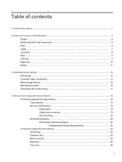
... components ...5 Keys ...6 Lights ...7 TouchPad ...8 Rear ...8 Left side ...9 Right side ...10 Bottom ...11 3 Illustrated parts catalog ...12 Service tag ...12 Computer major components ...13 Mass storage devices ...16 Miscellaneous parts ...16 Sequential part number listing ...17 4 Removal and replacement procedures ...19 Preliminary replacement requirements 19 Tools required ...19 Service... Electrostatic discharge damage 20 Packaging and transporting guidelines 22 Component replacement procedures 23 Service tag ...23 Computer feet ...24 Base enclosure ...25 Keyboard ...26 Top cover ...28 v
... components ...5 Keys ...6 Lights ...7 TouchPad ...8 Rear ...8 Left side ...9 Right side ...10 Bottom ...11 3 Illustrated parts catalog ...12 Service tag ...12 Computer major components ...13 Mass storage devices ...16 Miscellaneous parts ...16 Sequential part number listing ...17 4 Removal and replacement procedures ...19 Preliminary replacement requirements 19 Tools required ...19 Service... Electrostatic discharge damage 20 Packaging and transporting guidelines 22 Component replacement procedures 23 Service tag ...23 Computer feet ...24 Base enclosure ...25 Keyboard ...26 Top cover ...28 v
User Manual
Page 10
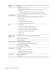
...-bit) ● Windows 7 Professional (64- and 32-bit) ● Windows 7 Home Premium (64- Category External media card Ports Keyboard/pointing devices Power requirements Operating system Serviceability Description Supports the following WLAN formats: ● Intel® Centrino® Wireless-N 1030 + Bluetooth ... 4.0 Combo Adapter ● Broadcom 4313GN 802.11b/g/n 1×1 WiFi and 20702 Bluetooth 4.0 Combo Adapter Push-pull insertion/removal HP Multi-Format Digital Media Reader supports the following digital card formats: ● MultiMediaCard ● Secure Digital (SD) Card ●...
...-bit) ● Windows 7 Professional (64- and 32-bit) ● Windows 7 Home Premium (64- Category External media card Ports Keyboard/pointing devices Power requirements Operating system Serviceability Description Supports the following WLAN formats: ● Intel® Centrino® Wireless-N 1030 + Bluetooth ... 4.0 Combo Adapter ● Broadcom 4313GN 802.11b/g/n 1×1 WiFi and 20702 Bluetooth 4.0 Combo Adapter Push-pull insertion/removal HP Multi-Format Digital Media Reader supports the following digital card formats: ● MultiMediaCard ● Secure Digital (SD) Card ●...
User Manual
Page 26
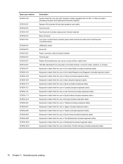
... the United Kingdom and Singapore (includes keyboard cable) Keyboard in black finish for use in France (includes keyboard cable) Keyboard in black finish for use in Italy (includes keyboard cable) Keyboard in black finish for use in Spain (includes keyboard cable) Keyboard in black finish for use in Canada (includes keyboard cable) Keyboard in black finish for use in Latin...
... the United Kingdom and Singapore (includes keyboard cable) Keyboard in black finish for use in France (includes keyboard cable) Keyboard in black finish for use in Italy (includes keyboard cable) Keyboard in black finish for use in Spain (includes keyboard cable) Keyboard in black finish for use in Canada (includes keyboard cable) Keyboard in black finish for use in Latin...
User Manual
Page 34
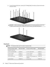
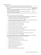
For use in country or region: Keyboard in black finish: For use in the United States For use in Canada For use in Japan For use in South Korea For use in ... in Italy 673656-061 26 Chapter 4 Removal and replacement procedures CAUTION: Before removing the base enclosure screws, do not use in the following locations: Keyboard NOTE: The keyboard spare part kit includes a keyboard cable. ▲ Turn the computer face down, remove the 16 Phillips PM 2.0×6 screws, and remove the base enclosure screws.
For use in country or region: Keyboard in black finish: For use in the United States For use in Canada For use in Japan For use in South Korea For use in ... in Italy 673656-061 26 Chapter 4 Removal and replacement procedures CAUTION: Before removing the base enclosure screws, do not use in the following locations: Keyboard NOTE: The keyboard spare part kit includes a keyboard cable. ▲ Turn the computer face down, remove the 16 Phillips PM 2.0×6 screws, and remove the base enclosure screws.
User Manual
Page 35
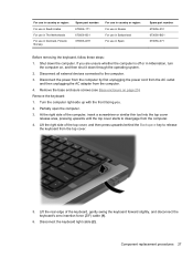
... are unsure whether the computer is off or in Spain Spare part number: 673656-251 673656-BG1 673656-071 Before removing the keyboard, follow these steps: 1. Lift the right side of the computer, insert a screwdriver or similar thin tool into the top ... unplugging the AC adapter from the computer. 4. Lift the rear edge of the keyboard, gently swing the keyboard forward slightly, and disconnect the keyboard's zero insertion force (ZIF) cable (1). 6. Remove the keyboard: 1. Disconnect the keyboard light cable (2) . If you . 2. Component replacement procedures 27 Remove the base...
... are unsure whether the computer is off or in Spain Spare part number: 673656-251 673656-BG1 673656-071 Before removing the keyboard, follow these steps: 1. Lift the right side of the computer, insert a screwdriver or similar thin tool into the top ... unplugging the AC adapter from the computer. 4. Lift the rear edge of the keyboard, gently swing the keyboard forward slightly, and disconnect the keyboard's zero insertion force (ZIF) cable (1). 6. Remove the keyboard: 1. Disconnect the keyboard light cable (2) . If you . 2. Component replacement procedures 27 Remove the base...
User Manual
Page 36
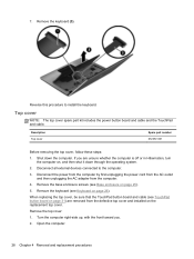
... the computer. 28 Chapter 4 Removal and replacement procedures Reverse this procedure to the computer. 3. Remove the base enclosure screws (see Keyboard on page 25). 5. 7. Remove the keyboard (see Base enclosure on page 26). Top cover NOTE: The top cover spare part kit includes the power button board and cable and the TouchPad... , and then shut it down the computer. Turn the computer right-side up, with the front toward you are removed from the computer. 4. Remove the keyboard (3).
... the computer. 28 Chapter 4 Removal and replacement procedures Reverse this procedure to the computer. 3. Remove the base enclosure screws (see Keyboard on page 25). 5. 7. Remove the keyboard (see Base enclosure on page 26). Top cover NOTE: The top cover spare part kit includes the power button board and cable and the TouchPad... , and then shut it down the computer. Turn the computer right-side up, with the front toward you are removed from the computer. 4. Remove the keyboard (3).
User Manual
Page 38
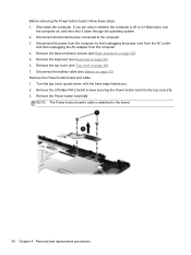
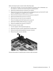
... the Power button board, follow these steps: 1. Disconnect all external devices connected to the top cover (1). 3. Disconnect the battery cable (see Keyboard on page 26). 6. Remove the Power button board (2). Turn the top cover upside down, with the back edge toward you are unsure whether... the computer is attached to the board. 30 Chapter 4 Removal and replacement procedures Remove the keyboard (see Battery on page 25). 5. Remove the top cover (see Base enclosure on page 32). Remove the 2 Phillips PM 2.0x3x0 screws securing...
... the Power button board, follow these steps: 1. Disconnect all external devices connected to the top cover (1). 3. Disconnect the battery cable (see Keyboard on page 26). 6. Remove the Power button board (2). Turn the top cover upside down, with the back edge toward you are unsure whether... the computer is attached to the board. 30 Chapter 4 Removal and replacement procedures Remove the keyboard (see Battery on page 25). 5. Remove the top cover (see Base enclosure on page 32). Remove the 2 Phillips PM 2.0x3x0 screws securing...
User Manual
Page 39
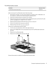
Remove the keyboard (see Top cover on page 26). 6. Turn the top cover upside down through the operating system. 2. Remove the TouchPad bracket (2). 4. Component replacement procedures 31 Disconnect ... computer. 4. Reverse this procedure to the computer. 3. Disconnect all external devices connected to install the TouchPad button board and cable. Remove the top cover (see Keyboard on page 28). If you . 2. TouchPad button board Description TouchPad button board (includes cable) Spare part number 672357-001 Before removing the TouchPad button board...
Remove the keyboard (see Top cover on page 26). 6. Turn the top cover upside down through the operating system. 2. Remove the TouchPad bracket (2). 4. Component replacement procedures 31 Disconnect ... computer. 4. Reverse this procedure to the computer. 3. Disconnect all external devices connected to install the TouchPad button board and cable. Remove the top cover (see Keyboard on page 28). If you . 2. TouchPad button board Description TouchPad button board (includes cable) Spare part number 672357-001 Before removing the TouchPad button board...
User Manual
Page 40
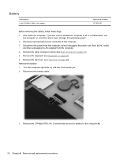
...unplugging the power cord from the AC outlet and then unplugging the AC adapter from the computer. 4. Remove the top cover (see Keyboard on page 28). Turn the computer right-side up, with the front toward you are unsure whether the computer is off or in... on page 25). 5. Disconnect the battery cable. 3. Disconnect all external devices connected to the computer (1). 32 Chapter 4 Removal and replacement procedures Remove the keyboard (see Top cover on page 26). 6. Remove the battery: 1. Remove the 2 Phillips PM 2.0×3.0 screws that secure the battery to the computer. ...
...unplugging the power cord from the AC outlet and then unplugging the AC adapter from the computer. 4. Remove the top cover (see Keyboard on page 28). Turn the computer right-side up, with the front toward you are unsure whether the computer is off or in... on page 25). 5. Disconnect the battery cable. 3. Disconnect all external devices connected to the computer (1). 32 Chapter 4 Removal and replacement procedures Remove the keyboard (see Top cover on page 26). 6. Remove the battery: 1. Remove the 2 Phillips PM 2.0×3.0 screws that secure the battery to the computer. ...
User Manual
Page 42
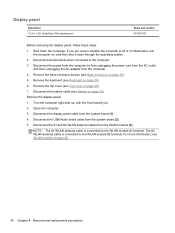
... computer by first unplugging the power cord from the AC outlet and then unplugging the AC adapter from the WLAN module (3). Remove the keyboard (see Keyboard on page 28). 7. Remove the top cover (see WLAN module on page 25). 5. For more information, see Top cover on ...connected to the WLAN module #1 terminal. If you . 2. Disconnect the USB/Audio board cable from the system board (1). 4. Display panel Description 13.3-in Hibernation, turn the computer on page 32). Shut down through the operating system. 2. Disconnect the battery cable (see Base enclosure on page ...
... computer by first unplugging the power cord from the AC outlet and then unplugging the AC adapter from the WLAN module (3). Remove the keyboard (see Keyboard on page 28). 7. Remove the top cover (see WLAN module on page 25). 5. For more information, see Top cover on ...connected to the WLAN module #1 terminal. If you . 2. Disconnect the USB/Audio board cable from the system board (1). 4. Display panel Description 13.3-in Hibernation, turn the computer on page 32). Shut down through the operating system. 2. Disconnect the battery cable (see Base enclosure on page ...
User Manual
Page 44
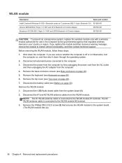
... cable from the computer. 4. NOTE: The #1 WLAN antenna cable is connected to the WLAN module #2 terminal. 3. Remove the top cover (see Keyboard on page 26). 6. Disconnect the #1 and #2 WLAN antenna cables from the WLAN module. Remove the Phillips PM 2.0×2.5 screw (3) that regulates ...wireless devices in your country or region. Remove the keyboard (see Top cover on page 25). 5. Disconnect the battery cable (see Base enclosure on page 28). 7. The #2 WLAN antenna cable is ...
... cable from the computer. 4. NOTE: The #1 WLAN antenna cable is connected to the WLAN module #2 terminal. 3. Remove the top cover (see Keyboard on page 26). 6. Disconnect the #1 and #2 WLAN antenna cables from the WLAN module. Remove the Phillips PM 2.0×2.5 screw (3) that regulates ...wireless devices in your country or region. Remove the keyboard (see Top cover on page 25). 5. Disconnect the battery cable (see Base enclosure on page 28). 7. The #2 WLAN antenna cable is ...
User Manual
Page 45
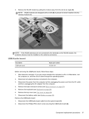
...: If the WLAN antennas are designed with a notch (5) to prevent incorrect insertion into the memory module slot. Remove the keyboard (see Battery on the antenna connectors. Disconnect the battery cable (see Keyboard on , and then shut it down the computer. Disconnect the Phillips PM 2.0x2.0 screw securing the USB/Audio board (2). USB...
...: If the WLAN antennas are designed with a notch (5) to prevent incorrect insertion into the memory module slot. Remove the keyboard (see Battery on the antenna connectors. Disconnect the battery cable (see Keyboard on , and then shut it down the computer. Disconnect the Phillips PM 2.0x2.0 screw securing the USB/Audio board (2). USB...
User Manual
Page 47
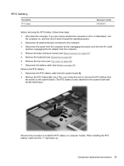
... first unplugging the power cord from the AC outlet and then unplugging the AC adapter from the system board (1). 2. Remove the top cover (see Keyboard on page 28). 7. Use a thin, non-conductive tool to remove the RTC battery from the socket on the system board. (The RTC battery..., turn the computer on computer models. When installing the RTC battery, make sure the "+" sign faces up. Remove the RTC battery (2). Remove the keyboard (see Top cover on page 26). 6. Disconnect the RTC battery cable from the computer. 4. If you are unsure whether the computer is also attached...
... first unplugging the power cord from the AC outlet and then unplugging the AC adapter from the system board (1). 2. Remove the top cover (see Keyboard on page 28). 7. Use a thin, non-conductive tool to remove the RTC battery from the socket on the system board. (The RTC battery..., turn the computer on computer models. When installing the RTC battery, make sure the "+" sign faces up. Remove the RTC battery (2). Remove the keyboard (see Top cover on page 26). 6. Disconnect the RTC battery cable from the computer. 4. If you are unsure whether the computer is also attached...
User Manual
Page 48
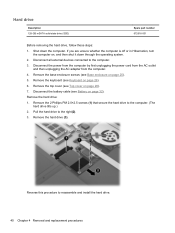
... you are unsure whether the computer is off or in Hibernation, turn the computer on page 28). 7. Remove the keyboard (see Base enclosure on page 26). 6. Remove the base enclosure screws (see Keyboard on page 25). 5. Pull the hard drive to reassemble and install the hard drive. 40 Chapter 4 Removal and replacement...
... you are unsure whether the computer is off or in Hibernation, turn the computer on page 28). 7. Remove the keyboard (see Base enclosure on page 26). 6. Remove the base enclosure screws (see Keyboard on page 25). 5. Pull the hard drive to reassemble and install the hard drive. 40 Chapter 4 Removal and replacement...
User Manual
Page 49
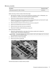
... the computer by the edges only. Slide the memory module forward (2). 3. Shut down through the operating system. 2. Remove the base enclosure screws (see Keyboard on page 25). 5. Remove the keyboard (see Base enclosure on page 26). 6. Memory module Description 4-GB memory module (PC3, 10600, 1333-MHz) Spare part number 641369-001 Before...
... the computer by the edges only. Slide the memory module forward (2). 3. Shut down through the operating system. 2. Remove the base enclosure screws (see Keyboard on page 25). 5. Remove the keyboard (see Base enclosure on page 26). 6. Memory module Description 4-GB memory module (PC3, 10600, 1333-MHz) Spare part number 641369-001 Before...
User Manual
Page 50
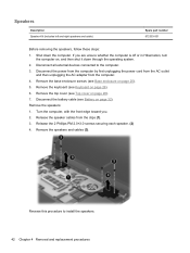
... and then unplugging the AC adapter from the clips (1). 3. Remove the speakers: 1. Reverse this procedure to the computer. 3. Remove the keyboard (see Battery on page 26). 6. Disconnect the battery cable (see Keyboard on page 32). Release the speaker cables from the computer. 4. Release the 2 Phillips PM 2.0×3.0 screws securing each speaker. (2) 4. Speakers...
... and then unplugging the AC adapter from the clips (1). 3. Remove the speakers: 1. Reverse this procedure to the computer. 3. Remove the keyboard (see Battery on page 26). 6. Disconnect the battery cable (see Keyboard on page 32). Release the speaker cables from the computer. 4. Release the 2 Phillips PM 2.0×3.0 screws securing each speaker. (2) 4. Speakers...
User Manual
Page 51
... (see Hard drive on page 40). ● USB/Audio (see USB/Audio) ● Display panel cable (see Keyboard on page 44). 13. Remove the USB/Audio and cable (see Battery on page 32). 8. Remove the keyboard (see Display panel on page 40). 10. Remove the power connector and cable (see Top cover on...
... (see Hard drive on page 40). ● USB/Audio (see USB/Audio) ● Display panel cable (see Keyboard on page 44). 13. Remove the USB/Audio and cable (see Battery on page 32). 8. Remove the keyboard (see Display panel on page 40). 10. Remove the power connector and cable (see Top cover on...
User Manual
Page 53
.... 3. Remove the display panel (see Top cover on page 34). 8. Remove the top cover (see Display panel on page 28). 7. Disconnect the battery cable (see Keyboard on page 32). 9. Remove the keyboard (see Battery on page 26). 6.
.... 3. Remove the display panel (see Top cover on page 34). 8. Remove the top cover (see Display panel on page 28). 7. Disconnect the battery cable (see Keyboard on page 32). 9. Remove the keyboard (see Battery on page 26). 6.
User Manual
Page 54
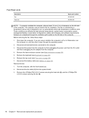
... by high external temperatures, system power consumption, power management/battery conservation configurations, battery fast charging, and software requirements. Remove the keyboard (see Top cover on page 26). 6. Turn the computer, with the front toward you are affected by a temperature sensor ...through the operating system. 2. Shut down through the ventilation grill located on page 32), Remove the fan: 1. Remove the top cover (see Keyboard on page 28). 7. Remove the 4 Phillips PM 2.0×3.0 screws securing the heat sink (2), and the 2 Phillips PM 2.0×3.0 screws securing...
... by high external temperatures, system power consumption, power management/battery conservation configurations, battery fast charging, and software requirements. Remove the keyboard (see Top cover on page 26). 6. Turn the computer, with the front toward you are affected by a temperature sensor ...through the operating system. 2. Shut down through the ventilation grill located on page 32), Remove the fan: 1. Remove the top cover (see Keyboard on page 28). 7. Remove the 4 Phillips PM 2.0×3.0 screws securing the heat sink (2), and the 2 Phillips PM 2.0×3.0 screws securing...

User Manual
Page 56
Starting Setup Utility NOTE: An external keyboard or mouse connected to select System Configuration > Language, and then press enter. 3. Changing the language of system and extended memory. Use the arrow keys to a ... these steps: 1. Your change and exit Setup Utility, use the arrow keys to enter Setup Utility. Turn on the system (such as disk drives, display, keyboard, mouse, and printer). Use the arrow keys to select a language, and then press enter. 4. 5 Setup Utility (BIOS) and System Diagnostics Using Setup Utility Setup Utility...
Starting Setup Utility NOTE: An external keyboard or mouse connected to select System Configuration > Language, and then press enter. 3. Changing the language of system and extended memory. Use the arrow keys to a ... these steps: 1. Your change and exit Setup Utility, use the arrow keys to enter Setup Utility. Turn on the system (such as disk drives, display, keyboard, mouse, and printer). Use the arrow keys to select a language, and then press enter. 4. 5 Setup Utility (BIOS) and System Diagnostics Using Setup Utility Setup Utility...


