
Service Manual
Page 15
HP color LaserJet 9500hdn printer dimensions (top and front views 29 Figure 7. Long, short, and diagonal grain curl 42 Figure 10. Wiring diagram (1 of 4 126 Figure 25. Connector location (1 of 4 114 Figure 21. T driver circuit 135 Figure 32. Sensors 142 Figure 38. Scanner motor ... 16. Power-on block diagram 110 Figure 18. Formatter system 146 Figure 39. Laser/scanner system 148 Figure 40. Color plane registration (CPR) adjustment 156 Figure 45. Laser beam skew calibration 157 Figure 46. Control panel layout 54 Figure 12. Engine-control ...
HP color LaserJet 9500hdn printer dimensions (top and front views 29 Figure 7. Long, short, and diagonal grain curl 42 Figure 10. Wiring diagram (1 of 4 126 Figure 25. Connector location (1 of 4 114 Figure 21. T driver circuit 135 Figure 32. Sensors 142 Figure 38. Scanner motor ... 16. Power-on block diagram 110 Figure 18. Formatter system 146 Figure 39. Laser/scanner system 148 Figure 40. Color plane registration (CPR) adjustment 156 Figure 45. Laser beam skew calibration 157 Figure 46. Control panel layout 54 Figure 12. Engine-control ...

Service Manual
Page 123
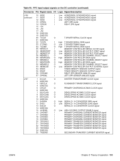
... 36 CPRSAR 37 CPRSAL I Low HORIZONTAL SYNCHRONOUS signal I Low HORIZONTAL SYNCHRONOUS signal I Low HORIZONTAL SYNCHRONOUS signal I LEFT CPR signal I RIGHT CPR signal O T DRIVER SERIAL CLOCK signal 1 High T DRIVER SERIAL DATA signal O Low T DRIVER TIMING signal O High...CONTROLLER DATA signal O MEMORY CONTROLLER CHANNEL SELECT signal O Low MEMORY CONTROLLER OUTPUT CONTROL signal I TONER DENSITY SENSOR OUTPUT signal I TONER DENSITY SENSOR OUTPUT signal I RIGHT CPR SENSOR ANALOG signal I LEFT CPR SENSOR ANALOG signal J107 1 DCCLK 2 GND(SG) 3 FBTCLK 4 GND(SG) 5 CHCLK 6 GND(...
... 36 CPRSAR 37 CPRSAL I Low HORIZONTAL SYNCHRONOUS signal I Low HORIZONTAL SYNCHRONOUS signal I Low HORIZONTAL SYNCHRONOUS signal I LEFT CPR signal I RIGHT CPR signal O T DRIVER SERIAL CLOCK signal 1 High T DRIVER SERIAL DATA signal O Low T DRIVER TIMING signal O High...CONTROLLER DATA signal O MEMORY CONTROLLER CHANNEL SELECT signal O Low MEMORY CONTROLLER OUTPUT CONTROL signal I TONER DENSITY SENSOR OUTPUT signal I TONER DENSITY SENSOR OUTPUT signal I RIGHT CPR SENSOR ANALOG signal I LEFT CPR SENSOR ANALOG signal J107 1 DCCLK 2 GND(SG) 3 FBTCLK 4 GND(SG) 5 CHCLK 6 GND(...

Service Manual
Page 157
... from the Beam detect PCA to the formatter. The DC controller writes CPR detection patterns in four colors on the ITB in the horizontal and vertical scanning directions. Scanner motor failure detection The main CPU monitors the /BDI signal that the CPR sensors measure to the commands from the formatter when the following occur...
... from the Beam detect PCA to the formatter. The DC controller writes CPR detection patterns in four colors on the ITB in the horizontal and vertical scanning directions. Scanner motor failure detection The main CPU monitors the /BDI signal that the CPR sensors measure to the commands from the formatter when the following occur...
Service Manual
Page 158
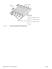
Color plane registration (CPR) adjustment 156 Chapter 5 Theory of operation ENWW CPR sensors Detection patterns ITB Standard color (C) CPR detection pattern Measured color (Y) Measured color (M) Measured color (K) Figure 44.
Color plane registration (CPR) adjustment 156 Chapter 5 Theory of operation ENWW CPR sensors Detection patterns ITB Standard color (C) CPR detection pattern Measured color (Y) Measured color (M) Measured color (K) Figure 44.

Service Manual
Page 331
... the consumables. 3 Check for poor contact or corrosion on the consumable and on again. Signs that a bad connection might exist include: z sensor failures z motor stalls z beam detect errors z OPC velocity errors z ITB velocity errors z developer sleeve motor stalls z cartridge (p and t)... memory errors z scanner velocity errors z formatter hangs z CPR failures z complete color plane dropouts z dead control panel z auger marks that there is a poor electrical connection include high-voltage arcing and a loss of ...
... the consumables. 3 Check for poor contact or corrosion on the consumable and on again. Signs that a bad connection might exist include: z sensor failures z motor stalls z beam detect errors z OPC velocity errors z ITB velocity errors z developer sleeve motor stalls z cartridge (p and t)... memory errors z scanner velocity errors z formatter hangs z CPR failures z complete color plane dropouts z dead control panel z auger marks that there is a poor electrical connection include high-voltage arcing and a loss of ...

Service Manual
Page 420
... log for the missing or light color. Check connector J3014 at the density sensor, intermediate connector J3072 and J3080, and connector J808 on the T driver PCA. 15 = yellow CPR sensor (the engine 5 cannot detect the yellow CPR pattern on the ITB) 16 = magenta CPR sensor (the engine cannot detect the magenta 6 CPR pattern on page 282. Numerical error...
... log for the missing or light color. Check connector J3014 at the density sensor, intermediate connector J3072 and J3080, and connector J808 on the T driver PCA. 15 = yellow CPR sensor (the engine 5 cannot detect the yellow CPR pattern on the ITB) 16 = magenta CPR sensor (the engine cannot detect the magenta 6 CPR pattern on page 282. Numerical error...

Service Manual
Page 421
... ITB if movement problems or damage exists. 8 Check connector J3073 and J3074 at the CPR sensors, intermediate connector J3080, and connector J808 on page 286. Chapter 7 Troubleshooting 419 dependent items for the specified color. 21 = yellow image drum t/d ratio sensor 2 Defeat the right side upper door 22 = magenta image drum t/d ratio (ITB access) interlocks...
... ITB if movement problems or damage exists. 8 Check connector J3073 and J3074 at the CPR sensors, intermediate connector J3080, and connector J808 on page 286. Chapter 7 Troubleshooting 419 dependent items for the specified color. 21 = yellow image drum t/d ratio sensor 2 Defeat the right side upper door 22 = magenta image drum t/d ratio (ITB access) interlocks...

Service Manual
Page 522
...and part numbers 497 delivery fan diagrams 141 removing and replacing 276 delivery feed assembly, diagrams and part numbers 495 delivery unit sensor, removing and replacing 239 delivery unit, removing and replacing 235 demo page, printing 58 density control operations 166, 167 image formation operations..., 126 consumables. cold reset paper size settings 79 performing 89 color band test 77 mode 69 plane registration (CPR) 155 settings 64 components block diagram 109 internal, diagrams and part numbers 454 testing 76 configuration page HP Jetdirect 437 using 328 disk. See hard disk DLC/LLC settings...
...and part numbers 497 delivery fan diagrams 141 removing and replacing 276 delivery feed assembly, diagrams and part numbers 495 delivery unit sensor, removing and replacing 239 delivery unit, removing and replacing 235 demo page, printing 58 density control operations 166, 167 image formation operations..., 126 consumables. cold reset paper size settings 79 performing 89 color band test 77 mode 69 plane registration (CPR) 155 settings 64 components block diagram 109 internal, diagrams and part numbers 454 testing 76 configuration page HP Jetdirect 437 using 328 disk. See hard disk DLC/LLC settings...

Service Manual
Page 524
... included 20 list, printing 58 PCL settings 63 foreign interface harness (FIH) 25 formatter cage, removing and replacing 289 color plane registration (CPR) 155 halftone calibration control 168 heartbeat LED 147 operations 146 part numbers 445 PCB, removing and replacing 288 power supplies...model number 21 troubleshooting 436 HP Jet-Link cabling, troubleshooting 323 HP Jet-Link connector 25 HP LaserJet utility, Macintosh firmware updates 103 HP media 33 HP PCL 5c driver 20 HP Web JetAdmin, firmware updates 104 humidity calibration control 166 meter, suppliers 44 sensor, removing and replacing 266...
... included 20 list, printing 58 PCL settings 63 foreign interface harness (FIH) 25 formatter cage, removing and replacing 289 color plane registration (CPR) 155 halftone calibration control 168 heartbeat LED 147 operations 146 part numbers 445 PCB, removing and replacing 288 power supplies...model number 21 troubleshooting 436 HP Jet-Link cabling, troubleshooting 323 HP Jet-Link connector 25 HP LaserJet utility, Macintosh firmware updates 103 HP media 33 HP PCL 5c driver 20 HP Web JetAdmin, firmware updates 104 humidity calibration control 166 meter, suppliers 44 sensor, removing and replacing 266...

Service Manual
Page 527
... paper custom sizes 83 default size 61, 79 finish test 42 HP 33 last sheet detection, tray 1 176 lifting operations 173 optimize settings 65 preprinted 37 print modes 64, 67 recommended 33 selecting 31 sensors 133 size detection operations 169, 171 sizes supported 32 storing 39 ... page counts 79 pages per minute (ppm) 20 panels. operations Beam detect errors 153, 155 block diagram 109 cassette detection 171 color plane registration (CPR) 155 connector location diagrams 126 DC controller 131, 134 density detection 167 dual-beam method 149 electrophotographic process 158 engine control system 130...
... paper custom sizes 83 default size 61, 79 finish test 42 HP 33 last sheet detection, tray 1 176 lifting operations 173 optimize settings 65 preprinted 37 print modes 64, 67 recommended 33 selecting 31 sensors 133 size detection operations 169, 171 sizes supported 32 storing 39 ... page counts 79 pages per minute (ppm) 20 panels. operations Beam detect errors 153, 155 block diagram 109 cassette detection 171 color plane registration (CPR) 155 connector location diagrams 126 DC controller 131, 134 density detection 167 dual-beam method 149 electrophotographic process 158 engine control system 130...

Service Manual
Page 11
...power supply circuit 149 Figure 37. Sensors 154 Figure 41. Laser control 162 Figure 45. Sample identification label 25 Figure 2. Front and right side assembly locations (HP LJ 9500 Series printer 28 Figure 3. HP color LaserJet 9500mfp dimensions 35 Figure 10. Maximum... HP LaserJet 9500 Series printer (3 of 4 138 Figure 28. Connector locations for the HP LaserJet 9500 Series printer (1 of 4 140 Figure 30. Fuser control circuit 148 Figure 36. Switches, solenoids, and clutches 154 Figure 40. Color-plane registration (CPR) adjustment 168 Figure 48. HP color LaserJet ...
...power supply circuit 149 Figure 37. Sensors 154 Figure 41. Laser control 162 Figure 45. Sample identification label 25 Figure 2. Front and right side assembly locations (HP LJ 9500 Series printer 28 Figure 3. HP color LaserJet 9500mfp dimensions 35 Figure 10. Maximum... HP LaserJet 9500 Series printer (3 of 4 138 Figure 28. Connector locations for the HP LaserJet 9500 Series printer (1 of 4 140 Figure 30. Fuser control circuit 148 Figure 36. Switches, solenoids, and clutches 154 Figure 40. Color-plane registration (CPR) adjustment 168 Figure 48. HP color LaserJet ...
Service Manual
Page 135
... 36 CPRSAR 37 CPRSAL I Low HORIZONTAL SYNCHRONOUS signal I Low HORIZONTAL SYNCHRONOUS signal I Low HORIZONTAL SYNCHRONOUS signal I LEFT CPR signal I RIGHT CPR signal O T DRIVER SERIAL CLOCK signal 1 High T DRIVER SERIAL DATA signal O Low T DRIVER TIMING signal O High...CONTROLLER DATA signal O MEMORY CONTROLLER CHANNEL SELECT signal O Low MEMORY CONTROLLER OUTPUT CONTROL signal I TONER DENSITY SENSOR OUTPUT signal I TONER DENSITY SENSOR OUTPUT signal I RIGHT CPR SENSOR ANALOG signal I LEFT CPR SENSOR ANALOG signal J107 1 DCCLK 2 GND(SG) 3 FBTCLK 4 GND(SG) 5 CHCLK 6 GND(...
... 36 CPRSAR 37 CPRSAL I Low HORIZONTAL SYNCHRONOUS signal I Low HORIZONTAL SYNCHRONOUS signal I Low HORIZONTAL SYNCHRONOUS signal I LEFT CPR signal I RIGHT CPR signal O T DRIVER SERIAL CLOCK signal 1 High T DRIVER SERIAL DATA signal O Low T DRIVER TIMING signal O High...CONTROLLER DATA signal O MEMORY CONTROLLER CHANNEL SELECT signal O Low MEMORY CONTROLLER OUTPUT CONTROL signal I TONER DENSITY SENSOR OUTPUT signal I TONER DENSITY SENSOR OUTPUT signal I RIGHT CPR SENSOR ANALOG signal I LEFT CPR SENSOR ANALOG signal J107 1 DCCLK 2 GND(SG) 3 FBTCLK 4 GND(SG) 5 CHCLK 6 GND(...

Service Manual
Page 169
... in response to determine the scanner rotation speed. Color-plane registration calibration control The color-plane registration (CPR) sensors detect CPR. The CPR calibration control performs the following functions: z image CPR range adjustment z laser-beam-skew calibration Image CPR adjustment Image CPR adjustment information is adjusted for each color to the formatter. The DC controller uses the detection pattern positions...
... in response to determine the scanner rotation speed. Color-plane registration calibration control The color-plane registration (CPR) sensors detect CPR. The CPR calibration control performs the following functions: z image CPR range adjustment z laser-beam-skew calibration Image CPR adjustment Image CPR adjustment information is adjusted for each color to the formatter. The DC controller uses the detection pattern positions...

Service Manual
Page 170
CPR sensors Detection patterns ITB Standard color (C) CPR detection pattern Measured color (Y) Measured color (M) Measured color (K) Figure 47. Color-plane registration (CPR) adjustment 168 Chapter 5 Theory of operation ENWW
CPR sensors Detection patterns ITB Standard color (C) CPR detection pattern Measured color (Y) Measured color (M) Measured color (K) Figure 47. Color-plane registration (CPR) adjustment 168 Chapter 5 Theory of operation ENWW

Service Manual
Page 360
Skin oil can break easily. Signs that a bad connection might exist include: z sensor failures z motor stalls z beam detect errors z OPC velocity errors z ITB velocity errors z developer sleeve motor stalls z cartridge (p and t) memory errors z scanner velocity errors z formatter hangs z CPR failures z complete color plane dropouts z dead control panel z auger marks that change direction z reversing stepper...
Skin oil can break easily. Signs that a bad connection might exist include: z sensor failures z motor stalls z beam detect errors z OPC velocity errors z ITB velocity errors z developer sleeve motor stalls z cartridge (p and t) memory errors z scanner velocity errors z formatter hangs z CPR failures z complete color plane dropouts z dead control panel z auger marks that change direction z reversing stepper...

Service Manual
Page 451
...assembly" on the ITB) Replace the density/color registration sensor assembly. This usually occurs 1 because the calibration patches are light or missing a color, check the T1 components, image drum,...15 = yellow CPR sensor (the engine 5 cannot detect the yellow CPR pattern on the ITB) 16 = magenta CPR sensor (the engine cannot detect the magenta 6 CPR pattern on page 296. Sensor abnormalities 1 are...on the temperature/humidity sensor, intermediate connector J3085, and connector J807 on the ITB. See"DC controller" on page 262. Also, check for the HP LaserJet 9500 Series printer (continued...
...assembly" on the ITB) Replace the density/color registration sensor assembly. This usually occurs 1 because the calibration patches are light or missing a color, check the T1 components, image drum,...15 = yellow CPR sensor (the engine 5 cannot detect the yellow CPR pattern on the ITB) 16 = magenta CPR sensor (the engine cannot detect the magenta 6 CPR pattern on page 296. Sensor abnormalities 1 are...on the temperature/humidity sensor, intermediate connector J3085, and connector J807 on the ITB. See"DC controller" on page 262. Also, check for the HP LaserJet 9500 Series printer (continued...

Service Manual
Page 452
... cleaning mechanism for the HP LaserJet 9500 Series printer (continued) Message Explanation Recommended action 54.XX PRINTER ERROR (continued) z 17 = cyan CPR sensor (the engine z 54.05 procedure: cannot detect the cyan CPR pattern 1 Clean the OHT sensor. Also, check for the missing or light color. See "DC controller" on the ITB) 18 = black CPR sensor (the engine 2 Check the...
... cleaning mechanism for the HP LaserJet 9500 Series printer (continued) Message Explanation Recommended action 54.XX PRINTER ERROR (continued) z 17 = cyan CPR sensor (the engine z 54.05 procedure: cannot detect the cyan CPR pattern 1 Clean the OHT sensor. Also, check for the missing or light color. See "DC controller" on the ITB) 18 = black CPR sensor (the engine 2 Check the...

Service Manual
Page 560
... 385 plane registration (CPR) 167 settings 70 communications, troubleshooting 466 components block diagram 121 internal, diagrams and part numbers 490 testing 83 configuration page HP Jetdirect 468 printing 64...replacing 290 delivery feed assembly, diagrams and part numbers 531 delivery unit sensor, removing and replacing 253 delivery unit, removing and replacing 249 demo page, printing 64...right, removing and replacing 213 tray 4, removing 318 upper right, removing and replacing 210 CPR (color plane registration) 167 CPU DC controller PCA 146, 147 tray 4 193 curl, grain test...
... 385 plane registration (CPR) 167 settings 70 communications, troubleshooting 466 components block diagram 121 internal, diagrams and part numbers 490 testing 83 configuration page HP Jetdirect 468 printing 64...replacing 290 delivery feed assembly, diagrams and part numbers 531 delivery unit sensor, removing and replacing 253 delivery unit, removing and replacing 249 demo page, printing 64...right, removing and replacing 213 tray 4, removing 318 upper right, removing and replacing 210 CPR (color plane registration) 167 CPU DC controller PCA 146, 147 tray 4 193 curl, grain test...

Service Manual
Page 562
...part numbers 479 included 23 list, printing 64 PCL settings 69 foreign interface harness (FIH) 28 formatter cage, removing and replacing 304 color plane registration (CPR) 167 halftone calibration control 180 heartbeat LED 159, 351 operations 158 part numbers 479 PCB, removing and replacing 302 power supplies 149 ... door, removing and replacing 218 drive assembly, diagrams and part numbers 512 drive assembly, removing and replacing 299 front paper sensor, removing and replacing 315 kit, part numbers 479 kit, resetting page count 86 media compatibility 42 motor test 345 removing and replacing ...
...part numbers 479 included 23 list, printing 64 PCL settings 69 foreign interface harness (FIH) 28 formatter cage, removing and replacing 304 color plane registration (CPR) 167 halftone calibration control 180 heartbeat LED 159, 351 operations 158 part numbers 479 PCB, removing and replacing 302 power supplies 149 ... door, removing and replacing 218 drive assembly, diagrams and part numbers 512 drive assembly, removing and replacing 299 front paper sensor, removing and replacing 315 kit, part numbers 479 kit, resetting page count 86 media compatibility 42 motor test 345 removing and replacing ...
Service Manual
Page 566
...paper custom sizes 91 default size 67, 86 detection operations 193 finish test 48 glossy 44 HP 39 last sheet detection, tray 1 188 level detection operations 193 lifting operations 185 optimize ... 71 preprinted 43 print modes 70, 73 recommended 39 rotate error messages 429 selecting 37 sensors 145 size detection operations 181, 183 sizes supported 38 storing 45 test tools 50 testing ...numbers 516 EN operations Beam detect errors 165, 167 block diagram 121 cassette detection 183 color plane registration (CPR) 167 connector location diagrams 138 DC controller 143, 146 density detection 179 dual-beam...
...paper custom sizes 91 default size 67, 86 detection operations 193 finish test 48 glossy 44 HP 39 last sheet detection, tray 1 188 level detection operations 193 lifting operations 185 optimize ... 71 preprinted 43 print modes 70, 73 recommended 39 rotate error messages 429 selecting 37 sensors 145 size detection operations 181, 183 sizes supported 38 storing 45 test tools 50 testing ...numbers 516 EN operations Beam detect errors 165, 167 block diagram 121 cassette detection 183 color plane registration (CPR) 167 connector location diagrams 138 DC controller 143, 146 density detection 179 dual-beam...


