HP PCL/PJL reference - Printer Job Language Technical Reference Addendum
Page 146
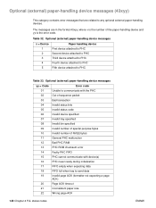
... device(s) 16 PHC never ready during initialization 17 FIFO empty when expecting data 18 FIFO full when tray to send data 19 Invalid page ACK (formatter not expecting a page ACK) 20 Page ACK timeout 21 Inconsistent paper size 22 Wrong page ACK 144 Chapter 4 PJL status codes ENWW Optional (external) paper...
... device(s) 16 PHC never ready during initialization 17 FIFO empty when expecting data 18 FIFO full when tray to send data 19 Invalid page ACK (formatter not expecting a page ACK) 20 Page ACK timeout 21 Inconsistent paper size 22 Wrong page ACK 144 Chapter 4 PJL status codes ENWW Optional (external) paper...
HP PCL/PJL reference - Printer Job Language Technical Reference Addendum
Page 150
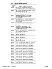
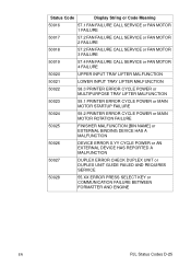
... 50029 50030 DUPLEX ERROR CHECK DUPLEX UNIT or DUPLEX UNIT GUIDE FAILED AND REQUIRES SERVICE 55.XX ERROR PRESS SELECT KEY or COMMUNICATION FAILURE BETWEEN FORMATTER AND ENGINE 64 PRINTER ERROR CYCLE POWER or VIDEO DMA TRANSFER TIMED OUT FAN MOTOR 5 FAILURE 50031 50032 50033 50034 50035 50036 50048 50049 50050...
... 50029 50030 DUPLEX ERROR CHECK DUPLEX UNIT or DUPLEX UNIT GUIDE FAILED AND REQUIRES SERVICE 55.XX ERROR PRESS SELECT KEY or COMMUNICATION FAILURE BETWEEN FORMATTER AND ENGINE 64 PRINTER ERROR CYCLE POWER or VIDEO DMA TRANSFER TIMED OUT FAN MOTOR 5 FAILURE 50031 50032 50033 50034 50035 50036 50048 50049 50050...
HP PCL/PJL reference - Printer Job Language Technical Reference Manual
Page 323
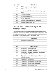
...need to open rear door of the jammed sheet. Remove toner cartridge to paper jams (for the LaserJet 4000 and 5000 series printers only). The messages are in the format 44xyy, where x is ...empty when expecting data FIFO full when tray to send data Invalid page ACK (formatter not expecting a page ACK) Page ACK timeout Inconsistent paper size Wrong page ACK Device(s) never ...ready during installation Negative ACK of ready tray LaserJet 4000 / 5000 Series Paper Jam Messages (44xyy) This category contains unsolicited status error messages ...
...need to open rear door of the jammed sheet. Remove toner cartridge to paper jams (for the LaserJet 4000 and 5000 series printers only). The messages are in the format 44xyy, where x is ...empty when expecting data FIFO full when tray to send data Invalid page ACK (formatter not expecting a page ACK) Page ACK timeout Inconsistent paper size Wrong page ACK Device(s) never ...ready during installation Negative ACK of ready tray LaserJet 4000 / 5000 Series Paper Jam Messages (44xyy) This category contains unsolicited status error messages ...
HP PCL/PJL reference - Printer Job Language Technical Reference Manual
Page 325
... 50027 DUPLEX ERROR CHECK DUPLEX UNIT or DUPLEX UNIT GUIDE FAILED AND REQUIRES SERVICE 50028 55.XX ERROR PRESS SELECT KEY or COMMUNICATION FAILURE BETWEEN FORMATTER AND ENGINE EN PJL Status Codes D-25
... 50027 DUPLEX ERROR CHECK DUPLEX UNIT or DUPLEX UNIT GUIDE FAILED AND REQUIRES SERVICE 50028 55.XX ERROR PRESS SELECT KEY or COMMUNICATION FAILURE BETWEEN FORMATTER AND ENGINE EN PJL Status Codes D-25

HP Color LaserJet 9500n/9500hdn - User Reference Guide
Page 61
...fonts and files. These tools are available through software and locked by locking the slot with the HP color LaserJet 9500hdn. For more information about compatible disk drive and formatter locks that are available from the Internet. Unlike standard printer memory, many items on page 75 or... the HP LaserJet Utility Help that is turned off. It is an optional accessory for the HP color LaserJet 9500n.) For security, the EIO...
...fonts and files. These tools are available through software and locked by locking the slot with the HP color LaserJet 9500hdn. For more information about compatible disk drive and formatter locks that are available from the Internet. Unlike standard printer memory, many items on page 75 or... the HP LaserJet Utility Help that is turned off. It is an optional accessory for the HP color LaserJet 9500n.) For security, the EIO...

HP Color LaserJet 9500n/9500hdn - User Reference Guide
Page 209
Slot label on the configuration page Slot 1 Slot 2 Slot 3 Slot 4 Incremental total On-board total Total Slot label on page 290) to install additional memory. The table lists the maximum amount of memory allowed for upgrade) 128 MB 128 MB 128 MB 384 MB 32 MB 416 MB 6 Managing the printer 207 Installing memory Use this procedure to find out how much memory is installed in the printer before adding more memory. Before you begin, print a configuration page (see "To print information pages" on the formatter board J1 J2 J3 J4 Description Firmware (not available for each DIMM slot.
Slot label on the configuration page Slot 1 Slot 2 Slot 3 Slot 4 Incremental total On-board total Total Slot label on page 290) to install additional memory. The table lists the maximum amount of memory allowed for upgrade) 128 MB 128 MB 128 MB 384 MB 32 MB 416 MB 6 Managing the printer 207 Installing memory Use this procedure to find out how much memory is installed in the printer before adding more memory. Before you begin, print a configuration page (see "To print information pages" on the formatter board J1 J2 J3 J4 Description Firmware (not available for each DIMM slot.

HP Color LaserJet 9500n/9500hdn - User Reference Guide
Page 210
.... 208 Printer memory and expansion ENWW Place it on the left side of the printer. 4 Grasp the black tab near the top and pull the formatter board out of the DIMM antistatic package and then touch bare metal on the printer. 3 1 If you have not already done so, print a configuration page...
.... 208 Printer memory and expansion ENWW Place it on the left side of the printer. 4 Grasp the black tab near the top and pull the formatter board out of the DIMM antistatic package and then touch bare metal on the printer. 3 1 If you have not already done so, print a configuration page...

HP Color LaserJet 9500n/9500hdn - User Reference Guide
Page 211
... side of the DIMM snap inward into place. (To remove a DIMM, the locks must be released.) 7 Holding the black tab near the top, slide the formatter board back into the slot (press firmly). Make sure 6 that the locks on each side of the DIMM slot are open, or outward.) See "Installing...
... side of the DIMM snap inward into place. (To remove a DIMM, the locks must be released.) 7 Holding the black tab near the top, slide the formatter board back into the slot (press firmly). Make sure 6 that the locks on each side of the DIMM slot are open, or outward.) See "Installing...

Service Manual
Page 7
... slots 146 Formatter heartbeat LED 147 Laser/scanner system 148 Dual-beam method 149 Laser control 150 Scanner-motor control 154 Color plane registration calibration control 155 Image formation system 158 Electrophotographic process 158 Image stabilization control 166 Paper-path system 169 Pickup/feed unit 171 Jam ...
... slots 146 Formatter heartbeat LED 147 Laser/scanner system 148 Dual-beam method 149 Laser control 150 Scanner-motor control 154 Color plane registration calibration control 155 Image formation system 158 Electrophotographic process 158 Image stabilization control 166 Paper-path system 169 Pickup/feed unit 171 Jam ...

Service Manual
Page 8
... fan 277 P-crg (image drum) drive assembly 278 T-crg (print cartridge) drive assembly 282 Fuser motor 284 Fuser drive assembly 285 DC controller 286 Formatter PCB 288 Formatter cage 289 High-voltage contact 291 Post charger power supply 292 Tray 1 pickup roller 294 Tray 1 separation pad 295 Left door switch 296 Right...
... fan 277 P-crg (image drum) drive assembly 278 T-crg (print cartridge) drive assembly 282 Fuser motor 284 Fuser drive assembly 285 DC controller 286 Formatter PCB 288 Formatter cage 289 High-voltage contact 291 Post charger power supply 292 Tray 1 pickup roller 294 Tray 1 separation pad 295 Left door switch 296 Right...

Service Manual
Page 15
...138 Figure 35. Motors and fans 139 Figure 36. Switches, solenoids, and clutches 142 Figure 37. Formatter system 146 Figure 39. Laser control 150 Figure 42. Color plane registration (CPR) adjustment 156 Figure 45. Sample seams 35 Figure 8. Connector location (3 of figures ... 26 Figure 5. Printable area from edges 85 Figure 13. Engine-control system 130 Figure 29. T driver circuit 135 Figure 32. HP color LaserJet 9500hdn printer dimensions (top and front views 29 Figure 7. Sensors 142 Figure 38. Maximum printable area 85 Figure 14. Fuser control ...
...138 Figure 35. Motors and fans 139 Figure 36. Switches, solenoids, and clutches 142 Figure 37. Formatter system 146 Figure 39. Laser control 150 Figure 42. Color plane registration (CPR) adjustment 156 Figure 45. Sample seams 35 Figure 8. Connector location (3 of figures ... 26 Figure 5. Printable area from edges 85 Figure 13. Engine-control system 130 Figure 29. T driver circuit 135 Figure 32. HP color LaserJet 9500hdn printer dimensions (top and front views 29 Figure 7. Sensors 142 Figure 38. Maximum printable area 85 Figure 14. Fuser control ...

Service Manual
Page 19
... 258. Engine test print page 335 Figure 264. Poorly fused image (1 of figures 17 Figure 227. Remove the formatter PCB 288 Figure 231. Unplug the formatter PCB connector 290 Figure 234. Remove the high-voltage contact 291 Figure 236. Remove the left door sensor 299 Figure... Print-quality assessment page (2 of 2 331 Figure 260. Lines, streaks, or scratches appear parallel to feed direction (1 of 2 344 Figure 268. Color plane misregistration 355 Figure 273. Paper path jam sensors 373 Figure 285. Repeating marks (98 mm 337 Figure 265. Wavy brush marks 354 Figure 272...
... 258. Engine test print page 335 Figure 264. Poorly fused image (1 of figures 17 Figure 227. Remove the formatter PCB 288 Figure 231. Unplug the formatter PCB connector 290 Figure 234. Remove the high-voltage contact 291 Figure 236. Remove the left door sensor 299 Figure... Print-quality assessment page (2 of 2 331 Figure 260. Lines, streaks, or scratches appear parallel to feed direction (1 of 2 344 Figure 268. Color plane misregistration 355 Figure 273. Paper path jam sensors 373 Figure 285. Repeating marks (98 mm 337 Figure 265. Wavy brush marks 354 Figure 272...

Service Manual
Page 81
... Set the total color page count if the formatter is replaced. FUSER KIT COUNT Set the total fuser kit page count if the formatter is replaced. In cases where the printer is not connected to zero after maintenance or repairs are displayed on the configuration page) z change the ... accomplished. The refurbished page count number is dependent on date for new printers. CLEANING KIT COUNT Set the total cleaning kit page count if the formatter is installed: z calibrate the staple position z review and edit the serial number of the output device z review and edit the page count of ...
... Set the total color page count if the formatter is replaced. FUSER KIT COUNT Set the total fuser kit page count if the formatter is replaced. In cases where the printer is not connected to zero after maintenance or repairs are displayed on the configuration page) z change the ... accomplished. The refurbished page count number is dependent on date for new printers. CLEANING KIT COUNT Set the total cleaning kit page count if the formatter is installed: z calibrate the staple position z review and edit the serial number of the output device z review and edit the page count of ...

Service Manual
Page 82
... month - 1) + calendar day = DDD. For instance, if the printer was installed. 2 Divide DDD by 30: 9 x 30 = 270. Restoring the Service ID If you replace the formatter, the date is the tenth month of 17. Use this menu item to reset the date to 270: 270 + 17 = 287. Calculate the date as...
... month - 1) + calendar day = DDD. For instance, if the printer was installed. 2 Divide DDD by 30: 9 x 30 = 270. Restoring the Service ID If you replace the formatter, the date is the tenth month of 17. Use this menu item to reset the date to 270: 270 + 17 = 287. Calculate the date as...

Service Manual
Page 90
... z default paper size z cold reset paper size z auto cleaning page size z total duplex counts z non-toner consumable counts z engine page count z color engine page count z tray 1 size z envelope feeder size z default unit of measure for default custom paper size z default unit of measure for each tray... counts z list of the values are saved include: z event/error log z model number z model name z printer name z printer serial number z formatter serial number z service ID (born-on for pixel count and EPR z consumables reorder url Use the following steps to perform a NVRAM reset: 1 Turn...
... z default paper size z cold reset paper size z auto cleaning page size z total duplex counts z non-toner consumable counts z engine page count z color engine page count z tray 1 size z envelope feeder size z default unit of measure for default custom paper size z default unit of measure for each tray... counts z list of the values are saved include: z event/error log z model number z model name z printer name z printer serial number z formatter serial number z service ID (born-on for pixel count and EPR z consumables reorder url Use the following steps to perform a NVRAM reset: 1 Turn...

Service Manual
Page 109
... 137 High-voltage power supply circuits 138 Post charger power supply unit 138 Motors and fans 139 Switches, solenoids, clutches, and sensors 142 Formatter 146 DIMM slots 146 Formatter heartbeat LED 147 Laser/scanner system 148 Dual-beam method 149 Laser control 150 Scanner-motor control 154 Image formation system 158 Electrophotographic...
... 137 High-voltage power supply circuits 138 Post charger power supply unit 138 Motors and fans 139 Switches, solenoids, clutches, and sensors 142 Formatter 146 DIMM slots 146 Formatter heartbeat LED 147 Laser/scanner system 148 Dual-beam method 149 Laser control 150 Scanner-motor control 154 Image formation system 158 Electrophotographic...

Service Manual
Page 110
To external devices through the formatter Printer systems Paper-pickup system 108 Chapter 5 Theory of operation ENWW Basic operation Major printer systems This chapter provides information about the following systems: z engine control (page 130) z formatter (page 146) z laser/scanner (page 148) z image formation (page 158) z paper pickup (page 169) Relationships among the four systems are represented in figure 15: Laser/scanner system Engine-control system Image-formation system Figure 15.
To external devices through the formatter Printer systems Paper-pickup system 108 Chapter 5 Theory of operation ENWW Basic operation Major printer systems This chapter provides information about the following systems: z engine control (page 130) z formatter (page 146) z laser/scanner (page 148) z image formation (page 158) z paper pickup (page 169) Relationships among the four systems are represented in figure 15: Laser/scanner system Engine-control system Image-formation system Figure 15.
Service Manual
Page 112
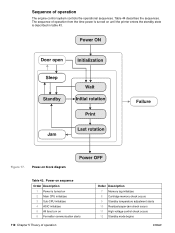
... 17. Power-on until the printer enters the standby state is turned on 2 Main CPU initializes 3 Sub-CPU initializes 4 ASIC initializes 5 All fans turn on 6 Formatter communication starts 110 Chapter 5 Theory of operation The engine-control system controls the operational sequences. Power-on sequence Order Description 1 Power is described in table...
... 17. Power-on until the printer enters the standby state is turned on 2 Main CPU initializes 3 Sub-CPU initializes 4 ASIC initializes 5 All fans turn on 6 Formatter communication starts 110 Chapter 5 Theory of operation The engine-control system controls the operational sequences. Power-on sequence Order Description 1 Power is described in table...

Service Manual
Page 113
...cleaning is complete z power on z main CPU, sub CPU, and ASIC initialize z power-supply-fan rotates z memory tags are checked z formatter interface communication starts z high-voltage control sequence (values are set and the secondary transfer roller is cleaned) z adjustment is made to reach ...occurs Chapter 5 Theory of the LSTR period FAILURE z TOP signal turns off z fuser temperature control occurs z TOP signal turns on (engine to formatter output signal) z image control occurs z high-voltage control occurs z paper pickup control occurs z next-page-pickup timing is coordinated z toner ...
...cleaning is complete z power on z main CPU, sub CPU, and ASIC initialize z power-supply-fan rotates z memory tags are checked z formatter interface communication starts z high-voltage control sequence (values are set and the secondary transfer roller is cleaned) z adjustment is made to reach ...occurs Chapter 5 Theory of the LSTR period FAILURE z TOP signal turns off z fuser temperature control occurs z TOP signal turns on (engine to formatter output signal) z image control occurs z high-voltage control occurs z paper pickup control occurs z next-page-pickup timing is coordinated z toner ...

Service Manual
Page 132
.... Engine-control system The engine-control system coordinates the laser/scanner, image-formation, and paper-pickup systems according to the instructions it receives from the formatter. Laser/scanner system Image formation system Paper pickup system Engine-control system DC controller PCA T driver PCA High-voltage power supply PCA Fuser control PCA...
.... Engine-control system The engine-control system coordinates the laser/scanner, image-formation, and paper-pickup systems according to the instructions it receives from the formatter. Laser/scanner system Image formation system Paper pickup system Engine-control system DC controller PCA T driver PCA High-voltage power supply PCA Fuser control PCA...


