Service Manual
Page 7
... Cover and Deflectors 7-8 Rollfeed Module 7-10 Back Platen Assembly 7-12 Electronics Module 7-14 Power Supply 7-16 Cutter Assemblies 7-18 Ink Delivery System 7-20 Service Station and Spittoon 7-22 Service Station Holder 7-24 Pinch-Wheel Assemblies 7-26 Scan-Axis Motor 7-28 Drive Roller Encoder Sensor 7-30 Print Platen Assembly 7-32 Carriage Assembly 7-34 Vacuum Fan...
... Cover and Deflectors 7-8 Rollfeed Module 7-10 Back Platen Assembly 7-12 Electronics Module 7-14 Power Supply 7-16 Cutter Assemblies 7-18 Ink Delivery System 7-20 Service Station and Spittoon 7-22 Service Station Holder 7-24 Pinch-Wheel Assemblies 7-26 Scan-Axis Motor 7-28 Drive Roller Encoder Sensor 7-30 Print Platen Assembly 7-32 Carriage Assembly 7-34 Vacuum Fan...

Service Manual
Page 8
... 8-33 Cutter Bushing 8-35 Cutter Guide Bracket 8-36 Drive Roller Encoder Sensor 8-38 Trailing Cable 8-40 Ink Supply Station 8-48 Interconnect PCA 8-50 Service Station and Aerosol Fan 8-52 Cutter Guide 8-55 Print Platen 8-56 Service Station Holder 8-57 Interconnect Cable 8-59 Ink Supply Tubes 8-60 Vacuum Fan 8-64 Pinch-Arm 8-66 Pinch-Arm Mechanism...
... 8-33 Cutter Bushing 8-35 Cutter Guide Bracket 8-36 Drive Roller Encoder Sensor 8-38 Trailing Cable 8-40 Ink Supply Station 8-48 Interconnect PCA 8-50 Service Station and Aerosol Fan 8-52 Cutter Guide 8-55 Print Platen 8-56 Service Station Holder 8-57 Interconnect Cable 8-59 Ink Supply Tubes 8-60 Vacuum Fan 8-64 Pinch-Arm 8-66 Pinch-Arm Mechanism...

Service Manual
Page 9
... Overview 10-2 Electrical System 10-3 Introduction 10-3 Hardware Description 10-3 Power Supply Unit (PSU) 10-5 Front Panel 10-6 Ink Delivery System (IDS) 10-7 Ink Supply Station (ISS) 10-7 Tubes Assembly 10-9 Service Station 10-10 Glossary Index Table of Contents HP DesignJets 500 and 800 Series Printers...
... Overview 10-2 Electrical System 10-3 Introduction 10-3 Hardware Description 10-3 Power Supply Unit (PSU) 10-5 Front Panel 10-6 Ink Delivery System (IDS) 10-7 Ink Supply Station (ISS) 10-7 Tubes Assembly 10-9 Service Station 10-10 Glossary Index Table of Contents HP DesignJets 500 and 800 Series Printers...
Service Manual
Page 33
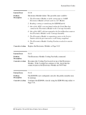
... connects the Electronics Module to fail, check that connects the Electronics Module to the Service Station while the previous move to the Carriage Assembly. 4. Corrective Action: Replace the Electronics Module ⇒ Page 8-24. HP DesignJets 500 and 800 Series Printers Service Manual 2-7 The Electronics Module Cooling Fan has reached its current limit. System Error...
... connects the Electronics Module to fail, check that connects the Electronics Module to the Service Station while the previous move to the Carriage Assembly. 4. Corrective Action: Replace the Electronics Module ⇒ Page 8-24. HP DesignJets 500 and 800 Series Printers Service Manual 2-7 The Electronics Module Cooling Fan has reached its current limit. System Error...

Service Manual
Page 37
... are not consistent with the expected length of blockage. Corrective Action: Replace the Service Station/Aerosol Fan Assembly ⇒ Page 8-52. HP DesignJets 500 and 800 Series Printers Service Manual 2-11 System Error Codes System Error: 21:10 Problem Description: Service Station failure. Reading, writing or initializing the backup EEROM failed. 2. The Aerosol Fan has reached...
... are not consistent with the expected length of blockage. Corrective Action: Replace the Service Station/Aerosol Fan Assembly ⇒ Page 8-52. HP DesignJets 500 and 800 Series Printers Service Manual 2-11 System Error Codes System Error: 21:10 Problem Description: Service Station failure. Reading, writing or initializing the backup EEROM failed. 2. The Aerosol Fan has reached...

Service Manual
Page 44
...cannot find the zero position of the Printer and cannot be moved out to Error Code 86:01. 2-18 HP DesignJets 500 and 800 Series Printers Service Manual Corrective Action: Refer to the center of the Print Platen it is stuck at the right hand side ...during the Carriage Movement test). System Error: 86:01 Problem Description: Carriage-Axis shutdown. If the percentage is bumping into the Service Station. Corrective Action: If this case replace the Service Station/Aerosol Fan Assembly ⇒ Page 8-52. n If the Error Code continues, replace the Drive Roller ⇒ Page 886...
...cannot find the zero position of the Printer and cannot be moved out to Error Code 86:01. 2-18 HP DesignJets 500 and 800 Series Printers Service Manual Corrective Action: Refer to the center of the Print Platen it is stuck at the right hand side ...during the Carriage Movement test). System Error: 86:01 Problem Description: Carriage-Axis shutdown. If the percentage is bumping into the Service Station. Corrective Action: If this case replace the Service Station/Aerosol Fan Assembly ⇒ Page 8-52. n If the Error Code continues, replace the Drive Roller ⇒ Page 886...

Service Manual
Page 64
... (69 cc), then replace the Ink Cartridge for that the Printer is causing the Printheads to fail. In the 3-18 HP DesignJets 500 and 800 Series Printers Service Manual In this situation, to perform the Prime Tubes Utility ⇒ Page 4-23). If the user replaces the Printhead after...faulty by the Printhead (Page 3-10, Obtaining Printhead Information). In the same way that is 3). If the usage of the Service Station is close to 100% then replace the Service Station ⇒ Page 8-52. 4 Check if the Ink Supply Tubes are faulty by installing new Start-up Printheads, replace the...
... (69 cc), then replace the Ink Cartridge for that the Printer is causing the Printheads to fail. In the 3-18 HP DesignJets 500 and 800 Series Printers Service Manual In this situation, to perform the Prime Tubes Utility ⇒ Page 4-23). If the user replaces the Printhead after...faulty by the Printhead (Page 3-10, Obtaining Printhead Information). In the same way that is 3). If the usage of the Service Station is close to 100% then replace the Service Station ⇒ Page 8-52. 4 Check if the Ink Supply Tubes are faulty by installing new Start-up Printheads, replace the...

Service Manual
Page 73
... to diagnose and resolve the possible source of all internal Service Tests available in the Printer. This test checks for entering the Service Tests menu are given on Page 4-4. 1 Ink Supply Station ⇒ Page 4-6 The purpose of this test is ...Page 6-4 The Printer contains an internal Troubleshooting procedure which will cause the Printhead to problems with the Service Station. HP DesignJets 500 and 800 Series Printers Service Manual 4-3 Service Tests and Utilities Service Tests (Diagnostics) The following problems: n Friction problems with worn out slider rod or Carriage Bushings...
... to diagnose and resolve the possible source of all internal Service Tests available in the Printer. This test checks for entering the Service Tests menu are given on Page 4-4. 1 Ink Supply Station ⇒ Page 4-6 The purpose of this test is ...Page 6-4 The Printer contains an internal Troubleshooting procedure which will cause the Printhead to problems with the Service Station. HP DesignJets 500 and 800 Series Printers Service Manual 4-3 Service Tests and Utilities Service Tests (Diagnostics) The following problems: n Friction problems with worn out slider rod or Carriage Bushings...
Service Manual
Page 78
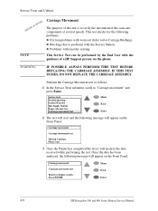
...Front Panel: Carriage movement Carriage movement test Moving Carriage. NOTE This Service Test can be performed by the End User with the Service Station. n Problems with worn out slider rod or Carriage Bushings. Service Tests and Utilities PHONE SUPPORT Carriage Movement The purpose of this ...test is to verify the movement of a HP Support person via the phone. Press ENTER Menu Back Enter 4-8 HP DesignJets 500 ...
...Front Panel: Carriage movement Carriage movement test Moving Carriage. NOTE This Service Test can be performed by the End User with the Service Station. n Problems with worn out slider rod or Carriage Bushings. Service Tests and Utilities PHONE SUPPORT Carriage Movement The purpose of this ...test is to verify the movement of a HP Support person via the phone. Press ENTER Menu Back Enter 4-8 HP DesignJets 500 ...

Service Manual
Page 83
n Identify potential problems. HP DesignJets 500 and 800 Series Printers Service Manual 4-13 Once unlocked, the Carriage Assembly can then be moved freely along the Printer by hand. 4 Prime Tubes ⇒ Page 4-23 The purpose of this Service Utility is to prime the Ink Supply Tubes after ... Page 4-25 The purpose of this Service Utility is to move the Carriage Assembly to a position where it . 3 Unlock Carriage ⇒ Page 4-22 The purpose of this Service Utility is to unlock the Carriage Assembly which is normally locked by the Service Station in the Printers. Instructions for call ...
n Identify potential problems. HP DesignJets 500 and 800 Series Printers Service Manual 4-13 Once unlocked, the Carriage Assembly can then be moved freely along the Printer by hand. 4 Prime Tubes ⇒ Page 4-23 The purpose of this Service Utility is to prime the Ink Supply Tubes after ... Page 4-25 The purpose of this Service Utility is to move the Carriage Assembly to a position where it . 3 Unlock Carriage ⇒ Page 4-22 The purpose of this Service Utility is to unlock the Carriage Assembly which is normally locked by the Service Station in the Printers. Instructions for call ...

Service Manual
Page 92
...the repair The Carriage will remain uncapped until another action (e.g. loading paper or replacing Printheads) is completed. 4-22 HP DesignJets 500 and 800 Series Printers Service Manual Make sure you leave the Carriage in a locked position once the repair is selected which is unlocked (Printheads .... Service utilities Change ink tubes Unlock Carriage Turn Drive Roller Prime tubes EEROM Setup Menu Back Enter 2 Once the utility starts, the printer will begin to unlock the Carriage Assembly and the following message will be moved freely along the Printer by the Service Station in...
...the repair The Carriage will remain uncapped until another action (e.g. loading paper or replacing Printheads) is completed. 4-22 HP DesignJets 500 and 800 Series Printers Service Manual Make sure you leave the Carriage in a locked position once the repair is selected which is unlocked (Printheads .... Service utilities Change ink tubes Unlock Carriage Turn Drive Roller Prime tubes EEROM Setup Menu Back Enter 2 Once the utility starts, the printer will begin to unlock the Carriage Assembly and the following message will be moved freely along the Printer by the Service Station in...

Service Manual
Page 98
...and the Printer is experiencing problems then try the following: 1 Replace the Pinch-Lift Mechanism ⇒ Page 8-67. Number of Service Station cycles represented as a percentage over the maximum number of cycles that the Printer is experiencing problems then try the following: 1 ...8658; Page 8-78. 4-28 HP DesignJets 500 and 800 Series Printers Service Manual n Cutter usage - If the percentage is more than 100% and the Printer is experiencing problems then try the following: 1 Replace the Cutter Assembly ⇒ Page 8-32. n Service Station usage - If the percentage is ...
...and the Printer is experiencing problems then try the following: 1 Replace the Pinch-Lift Mechanism ⇒ Page 8-67. Number of Service Station cycles represented as a percentage over the maximum number of cycles that the Printer is experiencing problems then try the following: 1 ...8658; Page 8-78. 4-28 HP DesignJets 500 and 800 Series Printers Service Manual n Cutter usage - If the percentage is more than 100% and the Printer is experiencing problems then try the following: 1 Replace the Cutter Assembly ⇒ Page 8-32. n Service Station usage - If the percentage is ...

Service Manual
Page 123
... Cover and Deflectors 7-8 Rollfeed Module 7-10 Back Platen Assembly 7-12 Electronics Module 7-14 Power Supply 7-16 Cutter Assemblies 7-18 Ink Delivery System 7-20 Service Station and Spittoon 7-22 Service Station Holder 7-24 Pinch-Wheel Assemblies 7-26 Scan-Axis Motor 7-28 Drive Roller Encoder Sensor 7-30 Print Platen Assembly 7-32 Carriage Assembly 7-34 Vacuum Fan...
... Cover and Deflectors 7-8 Rollfeed Module 7-10 Back Platen Assembly 7-12 Electronics Module 7-14 Power Supply 7-16 Cutter Assemblies 7-18 Ink Delivery System 7-20 Service Station and Spittoon 7-22 Service Station Holder 7-24 Pinch-Wheel Assemblies 7-26 Scan-Axis Motor 7-28 Drive Roller Encoder Sensor 7-30 Print Platen Assembly 7-32 Carriage Assembly 7-34 Vacuum Fan...

Service Manual
Page 144
Parts and Diagrams Service Station and Spittoon Reference on Drawing 1 2 3 Service Station and Spittoon HP Part Number Quantity Description/Comments C7769-60149 0624-0769 C7769-60165 1 Service Station/Aerosol Fan 2 Screw Plas 6-19 0.5 in 1 Left Spittoon Assembly 7-22 HP DesignJets 500 and 800 Series Printers Service Manual
Parts and Diagrams Service Station and Spittoon Reference on Drawing 1 2 3 Service Station and Spittoon HP Part Number Quantity Description/Comments C7769-60149 0624-0769 C7769-60165 1 Service Station/Aerosol Fan 2 Screw Plas 6-19 0.5 in 1 Left Spittoon Assembly 7-22 HP DesignJets 500 and 800 Series Printers Service Manual

Service Manual
Page 145
Parts and Diagrams 2 1 3 Figure 11: Service Station and Spittoon HP DesignJets 500 and 800 Series Printers Service Manual 7-23
Parts and Diagrams 2 1 3 Figure 11: Service Station and Spittoon HP DesignJets 500 and 800 Series Printers Service Manual 7-23

Service Manual
Page 146
Parts and Diagrams Service Station Holder Reference on Drawing 1 2 3 4 5 6 Service Station Holder HP Part Number Quantity Description/Comments C7769-60156 0515-2282 0624-0769 C7769-60173 0624-0769 C7769-60176 1 Service Station Holder (Right Hand Bracket) 4 Screw 2 Screw 1 Interconnect PCA 1 Screw 1 Tensioner Assembly Kit 7-24 HP DesignJets 500 and 800 Series Printers Service Manual
Parts and Diagrams Service Station Holder Reference on Drawing 1 2 3 4 5 6 Service Station Holder HP Part Number Quantity Description/Comments C7769-60156 0515-2282 0624-0769 C7769-60173 0624-0769 C7769-60176 1 Service Station Holder (Right Hand Bracket) 4 Screw 2 Screw 1 Interconnect PCA 1 Screw 1 Tensioner Assembly Kit 7-24 HP DesignJets 500 and 800 Series Printers Service Manual

Service Manual
Page 147
Parts and Diagrams 5 4 1 6 2 3 Figure 12: Service Station Holder HP DesignJets 500 and 800 Series Printers Service Manual 7-25
Parts and Diagrams 5 4 1 6 2 3 Figure 12: Service Station Holder HP DesignJets 500 and 800 Series Printers Service Manual 7-25

Service Manual
Page 167
... 8-33 Cutter Bushing 8-35 Cutter Guide Bracket 8-36 Drive Roller Encoder Sensor 8-38 Trailing Cable 8-40 Ink Supply Station 8-48 Interconnect PCA 8-50 Service Station and Aerosol Fan 8-52 Cutter Guide 8-55 Print Platen 8-56 Service Station Holder 8-57 Interconnect Cable 8-59 Ink Supply Tubes 8-60 Vacuum Fan 8-64 Pinch-Arm 8-66 Pinch-Arm Mechanism... Fork Idler, Tensioner and Idler Pulley 8-74 Encoder Strip 8-76 Carriage Assembly (Including Belt) 8-78 Paper-Axis Motor 8-84 Drive Roller 8-86 Gear Assemblies 8-92 HP DesignJets 500 and 800 Series Printers Service Manual 8-1
... 8-33 Cutter Bushing 8-35 Cutter Guide Bracket 8-36 Drive Roller Encoder Sensor 8-38 Trailing Cable 8-40 Ink Supply Station 8-48 Interconnect PCA 8-50 Service Station and Aerosol Fan 8-52 Cutter Guide 8-55 Print Platen 8-56 Service Station Holder 8-57 Interconnect Cable 8-59 Ink Supply Tubes 8-60 Vacuum Fan 8-64 Pinch-Arm 8-66 Pinch-Arm Mechanism... Fork Idler, Tensioner and Idler Pulley 8-74 Encoder Strip 8-76 Carriage Assembly (Including Belt) 8-78 Paper-Axis Motor 8-84 Drive Roller 8-86 Gear Assemblies 8-92 HP DesignJets 500 and 800 Series Printers Service Manual 8-1

Service Manual
Page 218
Disconnect the Service Station and Aerosol Fan Cables (connectors P5 and P9) from the Interconnect PCA. 8-52 HP DesignJets 500 and 800 Series Printers Service Manual Perform the Service Utility "Unlock Carriage" - Manually move the Carriage out of the Service Station. 4. Removal and Installation Service Station and Aerosol Fan Removal NOTE Refer to Page 8-7. 3. Remove the Right Hand Cover - Refer to the table on Page 8-4 for information on screw types. 1. Refer to Page 4-22. NOTE Switch off the Printer after performing this Utility. 2.
Disconnect the Service Station and Aerosol Fan Cables (connectors P5 and P9) from the Interconnect PCA. 8-52 HP DesignJets 500 and 800 Series Printers Service Manual Perform the Service Utility "Unlock Carriage" - Manually move the Carriage out of the Service Station. 4. Removal and Installation Service Station and Aerosol Fan Removal NOTE Refer to Page 8-7. 3. Remove the Right Hand Cover - Refer to the table on Page 8-4 for information on screw types. 1. Refer to Page 4-22. NOTE Switch off the Printer after performing this Utility. 2.

Service Manual
Page 219
Slide the Assembly towards you lift the Carriage Lock before sliding out the Service Station out of the Printer. 7. HP DesignJets 500 and 800 Series Printers Service Manual 8-53 Make sure you (to the right) and remove. Remove 2 T-15 screws (Type E) from inside the Service Station. 6. Removal and Installation 5.
Slide the Assembly towards you lift the Carriage Lock before sliding out the Service Station out of the Printer. 7. HP DesignJets 500 and 800 Series Printers Service Manual 8-53 Make sure you (to the right) and remove. Remove 2 T-15 screws (Type E) from inside the Service Station. 6. Removal and Installation 5.


