User Manual
Page 1
... Setting up your TV 20 2.1 Basic Connections 20 2.1.1 Power Connection 20 2.1.2 Connecting an Antenna or Cable TV 20 2.2 Connecting External Devices 21 2.2.1 Connecting External Earphones 21 2.2.2 Connecting to AV Devices 22 2.2.3 Connecting a VCR/ STB/ DVD Player Using Component Video 23 2.2.4 Connecting a VCR/ STB/ DVD Player Using Composite Video 23 2.2.5 Connecting a PC using VGA 24 2.2.6 Connecting a PC using DVI 24 2.2.7 Connecting HDMI 25 2.3 Using the TV 26 2.3.1 Turning the TV On and Off 26 2.3.2 Switching Source Signals 26 2.3.3 Performing an Automatic Channel Search...
... Setting up your TV 20 2.1 Basic Connections 20 2.1.1 Power Connection 20 2.1.2 Connecting an Antenna or Cable TV 20 2.2 Connecting External Devices 21 2.2.1 Connecting External Earphones 21 2.2.2 Connecting to AV Devices 22 2.2.3 Connecting a VCR/ STB/ DVD Player Using Component Video 23 2.2.4 Connecting a VCR/ STB/ DVD Player Using Composite Video 23 2.2.5 Connecting a PC using VGA 24 2.2.6 Connecting a PC using DVI 24 2.2.7 Connecting HDMI 25 2.3 Using the TV 26 2.3.1 Turning the TV On and Off 26 2.3.2 Switching Source Signals 26 2.3.3 Performing an Automatic Channel Search...
User Manual
Page 2
Using the Cable Organizer 52 2 Appendix: Remote Control Guide 37 6.1 Operation Modes 37 6.1.1 Switching Electronic Equipment Types 37 6.1.2 Setting Program Codes 37 6.1.3 Searching Codes 38 6.1.4 Setting Volume Lock 39 6.1.5 Setting Channel Lock 39 6.1.6 Factory Setting Mode 40 6.1.7 Description 42 6.2 Other Descriptions 42 6.2.1 Double Clicking 42 6.2.2 Buttons Information 42 6.2.3 Power-out Protection Capability 42 6.3 Component Program Codes 43 7. Troubleshooting 34 5. Adjusting On-Screen Display (OSD) Settings 28 3.1 OSD Setting Menus 29 3.2 Adjusting Picture Settings...
Using the Cable Organizer 52 2 Appendix: Remote Control Guide 37 6.1 Operation Modes 37 6.1.1 Switching Electronic Equipment Types 37 6.1.2 Setting Program Codes 37 6.1.3 Searching Codes 38 6.1.4 Setting Volume Lock 39 6.1.5 Setting Channel Lock 39 6.1.6 Factory Setting Mode 40 6.1.7 Description 42 6.2 Other Descriptions 42 6.2.1 Double Clicking 42 6.2.2 Buttons Information 42 6.2.3 Power-out Protection Capability 42 6.3 Component Program Codes 43 7. Troubleshooting 34 5. Adjusting On-Screen Display (OSD) Settings 28 3.1 OSD Setting Menus 29 3.2 Adjusting Picture Settings...
User Manual
Page 5
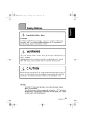
... of fire or electric shock, do so. Apparatus shall not be placed on the source signal, use by qualified service personnel only. Notes: • The LCD TV is for use a VGA monitor cable with liquids, such as vases, shall be exposed to dripping or splashing and no ... Safety Notices Installation Safety Notes Location Avoid allowing the TV to get prolonged exposure to sunlight or other than that contained in the operating instructions unless you are excluded. • This device uses a VGA connector to connect to a PC. Leave sufficient distance between the TV and the wall to rain ...
... of fire or electric shock, do so. Apparatus shall not be placed on the source signal, use by qualified service personnel only. Notes: • The LCD TV is for use a VGA monitor cable with liquids, such as vases, shall be exposed to dripping or splashing and no ... Safety Notices Installation Safety Notes Location Avoid allowing the TV to get prolonged exposure to sunlight or other than that contained in the operating instructions unless you are excluded. • This device uses a VGA connector to connect to a PC. Leave sufficient distance between the TV and the wall to rain ...
User Manual
Page 6
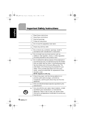
... a cart is used, use attachments/accessories specified by the manufacturer, or sold with the apparatus. Heed all instructions. 5. Do not install near water. 6. NOTE: Applies to avoid injury from the apparatus. 11. Keep these instructions. 2. A grounding-type plug has two blades and a third grounding prong. Read these instructions. 3. Install in accordance with the cart, stand, tripod, bracket, or table specified by the...
... a cart is used, use attachments/accessories specified by the manufacturer, or sold with the apparatus. Heed all instructions. 5. Do not install near water. 6. NOTE: Applies to avoid injury from the apparatus. 11. Keep these instructions. 2. A grounding-type plug has two blades and a third grounding prong. Read these instructions. 3. Install in accordance with the cart, stand, tripod, bracket, or table specified by the...
User Manual
Page 9
... in this manual is designed to enjoy superior audio and video while enriching your lifestyle with your TV. This instruction manual is subject to change without notice. The information in this manual has been carefully checked for purchasing a Hannspree Liquid Crystal Display Television (LCD TV). English 28US_LCDTV.book Page 9 Thursday, July 3, 2008 5:33 PM Preface Thank you in setting up , using the TV...
... in this manual is designed to enjoy superior audio and video while enriching your lifestyle with your TV. This instruction manual is subject to change without notice. The information in this manual has been carefully checked for purchasing a Hannspree Liquid Crystal Display Television (LCD TV). English 28US_LCDTV.book Page 9 Thursday, July 3, 2008 5:33 PM Preface Thank you in setting up , using the TV...
User Manual
Page 12
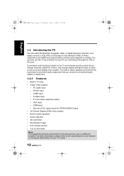
... supporting devices mentioned in stereo speakers provide full rich sound and a convenient audio output port lets you change channels, adjust the volume, and change display settings through the VGA or DVI port. HDMI input - You can watch NTSC/ATSC broadcast, cable, or digital television channels, and easily connect a VCR, STB or DVD player to the standard CVBS, S-Video, component, and HDMI input ports (location of R/ L audio inputs for your TV model. 12 VGA input - One set of these ports depends on different models. S-Video input - 3.5 mm stereo earphone output...
... supporting devices mentioned in stereo speakers provide full rich sound and a convenient audio output port lets you change channels, adjust the volume, and change display settings through the VGA or DVI port. HDMI input - You can watch NTSC/ATSC broadcast, cable, or digital television channels, and easily connect a VCR, STB or DVD player to the standard CVBS, S-Video, component, and HDMI input ports (location of R/ L audio inputs for your TV model. 12 VGA input - One set of these ports depends on different models. S-Video input - 3.5 mm stereo earphone output...
User Manual
Page 13
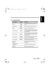
..., July 3, 2008 5:33 PM 1.3 Control Panel Description Button Power Input source Menu INPUT MENU Channel select CH Channel select CH Volume adjust Volume adjust Remote IR sensor Power/ Standby indicator Speakers VOL VOL Function Power button. Press to open the input source list. Press to increase the channel number or move to the previous item on the OSD menu. Press to increase the volume or move upward to the right on the OSD menu. Indicate power or standby status. Press to the...
..., July 3, 2008 5:33 PM 1.3 Control Panel Description Button Power Input source Menu INPUT MENU Channel select CH Channel select CH Volume adjust Volume adjust Remote IR sensor Power/ Standby indicator Speakers VOL VOL Function Power button. Press to open the input source list. Press to increase the channel number or move to the previous item on the OSD menu. Press to increase the volume or move upward to the right on the OSD menu. Indicate power or standby status. Press to the...
User Manual
Page 14
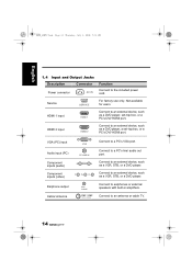
... a DVD player, set -top box, or a PC's DVI/ HDMI port. HDMI 2 input HDMI 2 Connect to an external device, such as a DVD player, a set -top box, or a PC's DVI/ HDMI port. Connect to an external device, such as a VCR, STB, or a DVD player. Not available for users. Connect to the included power cord. Service SERVICE For factory use only. 28US_LCDTV.book Page 14 Thursday, July 3, 2008 5:33 PM English 1.4 Input and Output Jacks Description Connector Power connector AC IN Function Connect to an antenna or cable...
... a DVD player, set -top box, or a PC's DVI/ HDMI port. HDMI 2 input HDMI 2 Connect to an external device, such as a DVD player, a set -top box, or a PC's DVI/ HDMI port. Connect to an external device, such as a VCR, STB, or a DVD player. Not available for users. Connect to the included power cord. Service SERVICE For factory use only. 28US_LCDTV.book Page 14 Thursday, July 3, 2008 5:33 PM English 1.4 Input and Output Jacks Description Connector Power connector AC IN Function Connect to an antenna or cable...
User Manual
Page 15
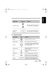
... -screen display menus. 15 Press to the last channel selected. S-V 1 Composite inputs AV2 R L AUDIO VIDEO AV1 AUDIO R L VIDEO Connect to an external device, such as a VCR, STB, or a DVD player. Use to turn the on-screen display (OSD) menu on/ off . Program entry Last Information Menu Arrows LAST INFO MENU Press this button after entering 2-digit program numbers. confirm the setting. Press to enter the program numbers (press 1 and 0 for channel 10). Press 09 to open the input source list. Press...
... -screen display menus. 15 Press to the last channel selected. S-V 1 Composite inputs AV2 R L AUDIO VIDEO AV1 AUDIO R L VIDEO Connect to an external device, such as a VCR, STB, or a DVD player. Use to turn the on-screen display (OSD) menu on/ off . Program entry Last Information Menu Arrows LAST INFO MENU Press this button after entering 2-digit program numbers. confirm the setting. Press to enter the program numbers (press 1 and 0 for channel 10). Press 09 to open the input source list. Press...
User Manual
Page 26
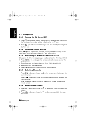
... specific channel number by pressing the number buttons on the remote control. 2.3.5 Adjusting the Volume 1 Press VOL+ on the control panel or VOL on the remote control to decrease the volume. 26 The power LED indicator on the control panel or remote control. English 28US_LCDTV.book Page 26 Thursday, July 3, 2008 5:33 PM 2.3 Using the TV 2.3.1 Turning the TV On and Off 1 Press on the TV changes from blue to set the signal source (Air or Cable, default...
... specific channel number by pressing the number buttons on the remote control. 2.3.5 Adjusting the Volume 1 Press VOL+ on the control panel or VOL on the remote control to decrease the volume. 26 The power LED indicator on the control panel or remote control. English 28US_LCDTV.book Page 26 Thursday, July 3, 2008 5:33 PM 2.3 Using the TV 2.3.1 Turning the TV On and Off 1 Press on the TV changes from blue to set the signal source (Air or Cable, default...
User Manual
Page 28
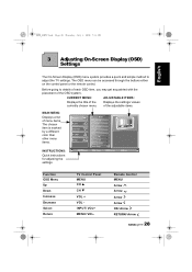
... menu items. INSTRUCTIONS: Quick instructions for adjusting the settings. Picture Audio Channel V-CHIP Setup Move Picture Mode Brightness Contrast Sharpness Color Tint Digital NR X-Contrast Aspect Ratio Next Page OK Enter Return Return Menu Exit Function OSD Menu Up Down Increase Decrease Select Return TV Control Panel MENU CH S CH T VOL + VOL INPUT/ VOL+ MENU/ VOL- The OSD menu can be accessed through the buttons either on the control panel or the remote control. Displays the settings/ values of the adjustable...
... menu items. INSTRUCTIONS: Quick instructions for adjusting the settings. Picture Audio Channel V-CHIP Setup Move Picture Mode Brightness Contrast Sharpness Color Tint Digital NR X-Contrast Aspect Ratio Next Page OK Enter Return Return Menu Exit Function OSD Menu Up Down Increase Decrease Select Return TV Control Panel MENU CH S CH T VOL + VOL INPUT/ VOL+ MENU/ VOL- The OSD menu can be accessed through the buttons either on the control panel or the remote control. Displays the settings/ values of the adjustable...
User Manual
Page 29
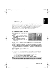
... Subtitle. on the control panel, to change the scales or press OK on the remote control or INPUT on the control panel to mark an item. 7 Press RETURN to return to the Picture menu. 8 Press MENU to exit the Picture menu. 9 The Picture menu can be used to adjust the Picture mode, Brightness, Contrast, Sharpness, Color, Tint, Digital NR, X-Contrast, Aspect Ratio, Color Temp and Recall settings. • The Picture Mode can be set to Vivid, Standard...
... Subtitle. on the control panel, to change the scales or press OK on the remote control or INPUT on the control panel to mark an item. 7 Press RETURN to return to the Picture menu. 8 Press MENU to exit the Picture menu. 9 The Picture menu can be used to adjust the Picture mode, Brightness, Contrast, Sharpness, Color, Tint, Digital NR, X-Contrast, Aspect Ratio, Color Temp and Recall settings. • The Picture Mode can be set to Vivid, Standard...
User Manual
Page 30
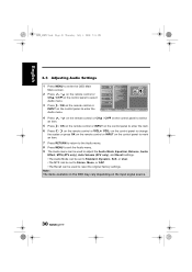
... Audio Mode, Equalizer, Balance, Audio Effect, MTS (ATV only), Auto Volume (ATV only), and Recall settings. •The Audio Mode can be set to Standard, Dynamic, Soft, or User. •The MTS can be set to Stereo, Mono, or SAP. •The Recall can be used to enter the OSD Main Menu screen. on the control panel to change the scales or press OK on the remote control or INPUT on the input signal source...
... Audio Mode, Equalizer, Balance, Audio Effect, MTS (ATV only), Auto Volume (ATV only), and Recall settings. •The Audio Mode can be set to Standard, Dynamic, Soft, or User. •The MTS can be set to Stereo, Mono, or SAP. •The Recall can be used to enter the OSD Main Menu screen. on the control panel to change the scales or press OK on the remote control or INPUT on the input signal source...
User Manual
Page 31
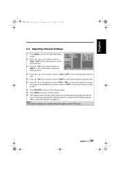
... control panel to enter the OSD Main Menu Picture screen. on the control panel to change the scales or press OK on the remote control or INPUT on the control panel to mark an item. 7 Press RETURN to return to the Channel menu. 8 Press MENU to exit the Channel menu. 9 The Channel menu can be used to TV source. 31 Note: The Channel settings are available when the signal is set to perform a channel search and edit channel list...
... control panel to enter the OSD Main Menu Picture screen. on the control panel to change the scales or press OK on the remote control or INPUT on the control panel to mark an item. 7 Press RETURN to return to the Channel menu. 8 Press MENU to exit the Channel menu. 9 The Channel menu can be used to TV source. 31 Note: The Channel settings are available when the signal is set to perform a channel search and edit channel list...
User Manual
Page 33
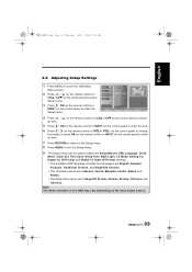
... Menu screen. Move OK Enter Return Return Menu Exit 4 Press / an item. 28US_LCDTV.book Page 33 Thursday, July 3, 2008 5:33 PM English 3.6 Adjusting Setup Settings 1 Press MENU to enter the Setup menu. Picture Audio Setup Wizard OSD Language Clock Mode 2 Press / on the remote control or CHS / CHT on the control panel to select Setup menu. 3 Press / OK on the remote control or Channel V-CHIP Setup Clock Set Time Zone Sleep Time Back Light CC Mode Analog CC INPUT on the input signal source...
... Menu screen. Move OK Enter Return Return Menu Exit 4 Press / an item. 28US_LCDTV.book Page 33 Thursday, July 3, 2008 5:33 PM English 3.6 Adjusting Setup Settings 1 Press MENU to enter the Setup menu. Picture Audio Setup Wizard OSD Language Clock Mode 2 Press / on the remote control or CHS / CHT on the control panel to select Setup menu. 3 Press / OK on the remote control or Channel V-CHIP Setup Clock Set Time Zone Sleep Time Back Light CC Mode Analog CC INPUT on the input signal source...
User Manual
Page 34
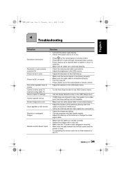
... the Auto Scan function in the OSD menus. Check the antenna and the video signal line connections. Make sure the video signal cable is connected securely. Choose programs with a new one. Make sure the TV power cord is clear. Press channel up on the control panel or remote control. Make sure all cables are not available. Adjust the direction of interference. Make sure the path between the remote control and the sensor is plugged...
... the Auto Scan function in the OSD menus. Check the antenna and the video signal line connections. Make sure the video signal cable is connected securely. Choose programs with a new one. Make sure the TV power cord is clear. Press channel up on the control panel or remote control. Make sure all cables are not available. Adjust the direction of interference. Make sure the path between the remote control and the sensor is plugged...
User Manual
Page 39
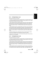
... equipment even under current CABLE mode, just 39 During the setting process, releasing the electronic equipment button exits the setting mode immediately without changing the status prior to the assigned electronic equipment even under current mode (for 200ms and then go off and setting mode is exited. 4. and MUTE. 6.1.5 Setting Channel Lock Operating procedures are not functional during search. The indicator light then goes off...
... equipment even under current CABLE mode, just 39 During the setting process, releasing the electronic equipment button exits the setting mode immediately without changing the status prior to the assigned electronic equipment even under current mode (for 200ms and then go off and setting mode is exited. 4. and MUTE. 6.1.5 Setting Channel Lock Operating procedures are not functional during search. The indicator light then goes off...
User Manual
Page 41
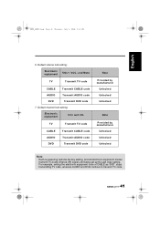
...TV Transmit TV code CABLE Transmit CABLE code AUDIO Transmit AUDIO code DVD Transmit DVD code 7. TV Transmit TV code CABLE AUDIO DVD Transmit CABLE code Transmit AUDIO code Transmit DVD code Note Provided by manufacturer Unlocked Unlocked Unlocked Note Provided by manufacturer Unlocked Unlocked Unlocked Note: Each re-powering restores factory setting, and all electronic equipment modes transmit TV-mode infrared (IR) signal until being set up through code setting. Default volume lock setting: Electronic equipment VOL+, VOL- Default channel lock setting: Electronic equipment...
...TV Transmit TV code CABLE Transmit CABLE code AUDIO Transmit AUDIO code DVD Transmit DVD code 7. TV Transmit TV code CABLE AUDIO DVD Transmit CABLE code Transmit AUDIO code Transmit DVD code Note Provided by manufacturer Unlocked Unlocked Unlocked Note Provided by manufacturer Unlocked Unlocked Unlocked Note: Each re-powering restores factory setting, and all electronic equipment modes transmit TV-mode infrared (IR) signal until being set up through code setting. Default volume lock setting: Electronic equipment VOL+, VOL- Default channel lock setting: Electronic equipment...
User Manual
Page 51
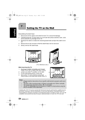
... removed. 5 Gently remove the stand base. ( For reference only ) Wall mounting the TV: 1 Purchase a VESA compatible wall bracket: VESA 100 X 200, 6 holes, M4, 8mm, 20 kg. 2 Locate your specific wall bracket to properly wall mount the TV. • The pitch of the mounting holes is 100mm horizontally and 100mm vertically. • The screws type required is metric: M4, 8 mm length. • The 28" TV stand base can ask a qualified service personnel about using the 6 mount...
... removed. 5 Gently remove the stand base. ( For reference only ) Wall mounting the TV: 1 Purchase a VESA compatible wall bracket: VESA 100 X 200, 6 holes, M4, 8mm, 20 kg. 2 Locate your specific wall bracket to properly wall mount the TV. • The pitch of the mounting holes is 100mm horizontally and 100mm vertically. • The screws type required is metric: M4, 8 mm length. • The 28" TV stand base can ask a qualified service personnel about using the 6 mount...
Brochure
Page 1
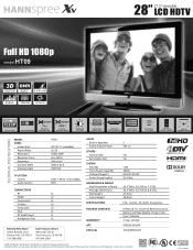
... FULL HD 1080P COLOR ENHANCER CELERATE 3ms OVERDRIVE RESPONSE TIME CONTRAST 3000:1 DYNAMIC CONTRAST RATIO MAXBRIGHT LCD PANEL SMARTLINK ULTRA-WIDE VIEWING ANGLE HDMI, VGA, YPbPr & COMPOSITE USER-FRIENDLY MENU SCREEN COMBO TUNER ATSC / NTSC / CLEAR QAM UNIVERSAL REMOTE CONTROL VIRTUAL SURROUND SOUND TECHNICAL SPECIFICATIONS MODEL PANEL Screen Size Aspect Ra o Resolu on Response Time Brightness Contrast Ra o Viewing Angle TV SYSTEM Tuners Audio System CONNECTIONS RF HDMI Component S-Video Composite VGA PC Audio Input Headphone Out HT09 28" (27...
... FULL HD 1080P COLOR ENHANCER CELERATE 3ms OVERDRIVE RESPONSE TIME CONTRAST 3000:1 DYNAMIC CONTRAST RATIO MAXBRIGHT LCD PANEL SMARTLINK ULTRA-WIDE VIEWING ANGLE HDMI, VGA, YPbPr & COMPOSITE USER-FRIENDLY MENU SCREEN COMBO TUNER ATSC / NTSC / CLEAR QAM UNIVERSAL REMOTE CONTROL VIRTUAL SURROUND SOUND TECHNICAL SPECIFICATIONS MODEL PANEL Screen Size Aspect Ra o Resolu on Response Time Brightness Contrast Ra o Viewing Angle TV SYSTEM Tuners Audio System CONNECTIONS RF HDMI Component S-Video Composite VGA PC Audio Input Headphone Out HT09 28" (27...


